Posted on Leave a comment

Is a IGBT module with no measurement issues necessarily a good module?

This article only discusses the inverter module made of a single or double IGBT tube, as well as the methods for measuring and judging its quality. The IPM module is not within the scope of this article’s discussion.
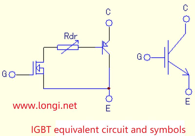
Field effect transistors have the advantages of fast switching speed and voltage control, but they also have the disadvantages of large conduction voltage drop and small voltage and current capacity. However, bipolar devices have exactly the opposite characteristics, such as current control, small conduction and voltage drop, and large power capacity. The combination of the two is known as complementary advantages. The origin of IGBT tubes or IGBT modules is based on this. Structurally, similar to the familiar composite amplifier transistor, the output transistor is a PNP type transistor, while the excitation transistor is a field-effect transistor, and the drain current of the latter forms the base current of the former. The amplification ability is the product of two tubes.
The equivalent circuit and symbols of IGBT tubes are shown in the following figure:
The pin function diagram of commonly used IGBT single and double tube modules (CM200Y-24NF) is as follows:
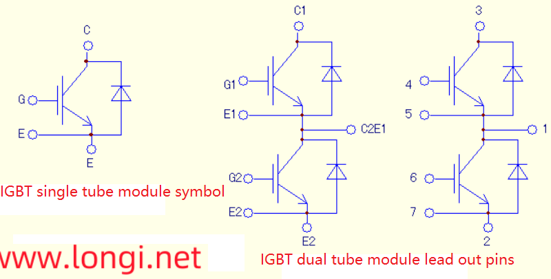
Pin function diagram of FP24R12KE3 integrated module:

Before disassembling, a rough measurement of the quality of the module can be made to make a preliminary judgment. For example, terminals 4, 5, and 6 are the U, V, and W output terminals of the frequency converter, while terminals 22 and 24 are the P (+) and N (-) terminals of the internal DC main circuit of the frequency converter, respectively. After identifying these 5 terminals, measurements can be made using a digital or pointer type multimeter. U. The V and W terminals all have forward and reverse resistance to the P and N terminals. Under normal conditions of IGBT tubes, the resistance between tubes C and E is infinite. Only the forward and reverse resistance of the six diodes in parallel on the tube can be measured. If terminals 4, 5, and 6 are considered as three-phase AC input terminals, the six diodes are equivalent to a three-phase rectifier bridge circuit. The method of measuring and judging the three-phase rectifier bridge is sufficient.

A. Online measurement:
If the measurement of this three-phase rectifier bridge is abnormal, it indicates that the module is damaged;
It is normal to measure this three-phase rectifier bridge, but it cannot be determined whether the module is good. The main circuit board of the frequency converter should be opened for further measurement and verification. Measure whether the triggering terminal and internal circuit are normal. Due to the fact that a resistor of about 10k (3k in parallel for high-power models) is often connected in parallel on the trigger terminal, both the forward and reverse online resistances of the trigger terminal should be the resistance value of the parallel resistor. The resistance values of these 6 trigger terminals should be the same. If there is a difference in the forward and reverse resistance of a certain triggering terminal, or if there is a decrease in resistance, after ruling out the fault of the driving circuit, it indicates that the module has been damaged.
The resistance measurement of the triggering terminal is also normal, and in general, the module is considered to be basically good. But it seems too early to announce that the module is absolutely fine at this time. See later on.
B. Offline measurement:

  1. This method is commonly used for measuring high-power single and dual modules, as well as newly purchased integrated modules.
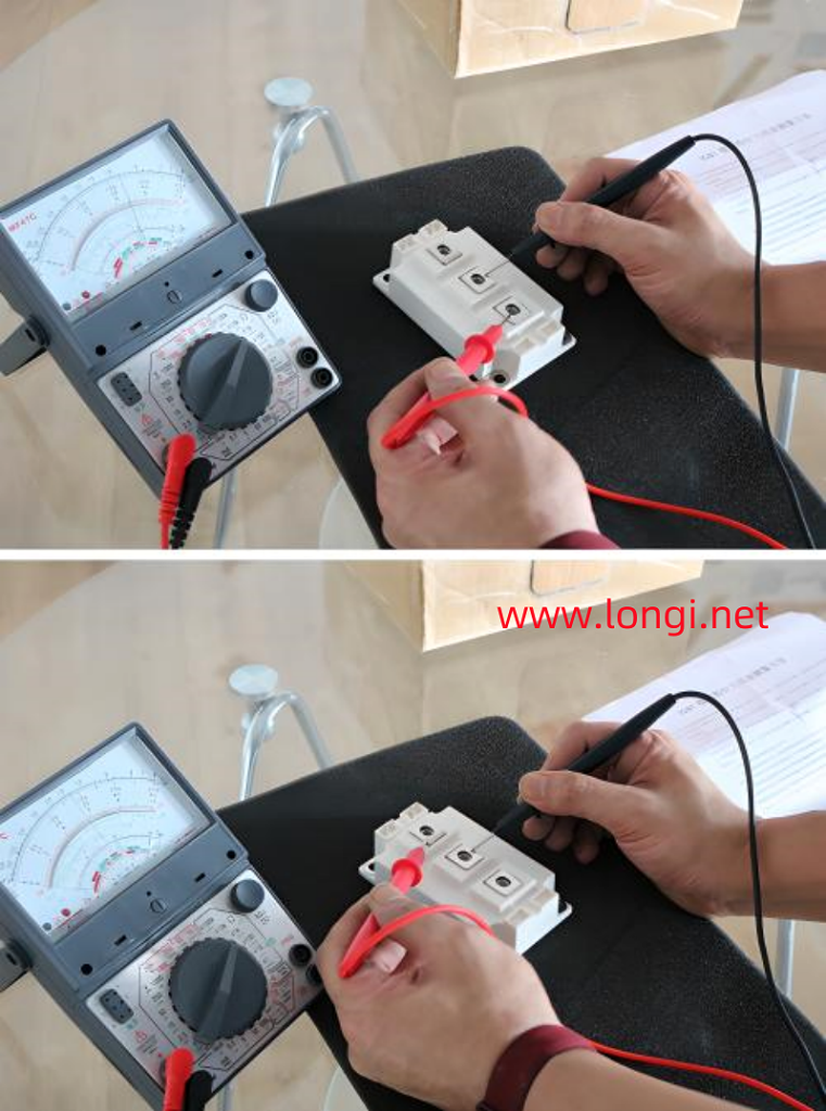
    After disconnecting the single and double transistor modules from the circuit (or for newly purchased modules), the measurement field-effect transistor (MOSFET) method can be used for testing. There is a junction capacitance between the gate and cathode of MOSFET, which determines its extremely high input impedance and charge retention function. This feature can be effectively used to detect the quality of IGBT tubes.
    The method is to set the pointer type multimeter to x10k, connect the black meter to pole C, and the red meter to pole E. At this point, the measured resistance value is almost infinite; Set up the pen without moving, touch the C and G poles with your fingers and remove them, indicating a decrease in resistance from infinity to around 200k; After a few seconds or even longer, measure the resistance between C and E again (with the black probe still connected to the C pole), which can still protect the resistance of about 200k from changing; Set up the pen without moving, short circuit the G and E poles with your finger, and the resistance between the C and E poles will become close to infinity again.
    In fact, touching C and G with your finger charges the gate and anode capacitors. After removing your finger, there is no discharge circuit for the capacitor, so the charge on the capacitor can be maintained for a period of time. The charging voltage on this capacitor is a forward excitation voltage, causing slight conduction of the IGBT tube and reducing the resistance between C and E; When shorting G and E with your fingers for the second time, a discharge path for the capacitor is provided. As the charge is discharged, the excitation voltage of the IGBT disappears, the tube becomes cut off, and the resistance between C and E tends to infinity.
    Fingers are equivalent to a resistance of k Ω level, providing a path for charging and discharging gate cathode junction capacitors; Due to the high forward excitation voltage (above 10V) required for the conduction of IGBT tubes, the x10k range of the multimeter is used, and the internal battery power supply in this range is 9V or 12V to meet the amplitude of the IGBT tube excitation voltage.
    The measurement of trigger terminals can also be measured with a capacitance meter to increase the accuracy of judgment. Often, modules with high power capacity have slightly higher capacitance values between the two terminals.
  2. Below are the dual tube modules CM100DU-24H and SKM75GB128DE, as well as the integrated module FP24R12KE3, using an MF47C pointer multimeter, × Data measured at 10k levels:
    CM200Y-24NF module: main terminal C1, C2E1 E2 trigger terminal C1 E1 C2 E2; After triggering, the resistance for C and E is 250k;
    The measurement using a capacitance meter in the 200nF range is 36.7nF, and the reverse measurement (with the black pen connected to the G terminal and the red pen connected to the E terminal) is 50 nF.
    The main terminal of SKM75GB128DE is the same as above, and after triggering, the C and E resistances are 250k;
    Trigger terminal capacitance: Measure 4.1 nF forward and 12.3 nF backward.
    FP24R12KE3 integrated module, this method can also be used, with a C and E resistance of around 200k after triggering;
    Trigger terminal capacitance forward measurement 6.9 nF, reverse measurement 10.1 nF.
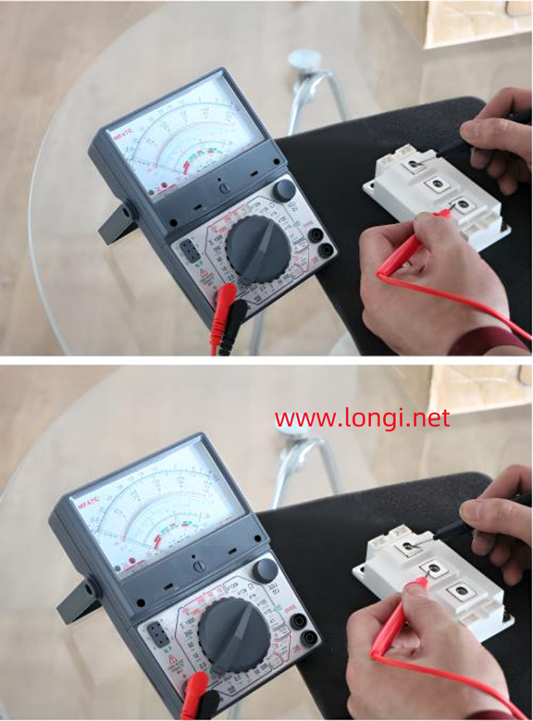
C. The power on measurement after online or offline measurement can finally determine the quality of the module:
Repair a 37kW Dongyuan frequency converter. Upon inspection, it was found that the inverter module was damaged, with model CM100DU-24H. After purchasing a module of the same type, I went through all the offline measurement procedures and confirmed that there were no issues with the module before installing it for testing. The three-phase output voltage is very unbalanced. After thoroughly checking the drive circuit to confirm that there are no faults, measure the zero line of the three-phase power supply from the U, V, and W outputs (using a pointer type multimeter in the DC 500V range). The DC components of the U and W phases are zero, while the V phase has a DC negative pressure of about 300V. From this, it can be concluded that the conduction of the V-phase lower tube is good, while the conduction of the upper tube is poor, resulting in a negative voltage output of V relative to the zero line. And the V-phase upper tube happens to be the newly replaced module. After purchasing another CM100DU-24H for replacement, the three-phase output is normal. The malfunction of the tube is that the internal MOSEFT tube is normal, so online or offline measurements are normal, while the internal output C and E poles have increased internal resistance due to conduction. It illustrates one thing that even after careful measurement, it cannot be 100% concluded that there is no problem with a good inverter module. The measurement and judgment ability of a multimeter is limited after all. Do not have preconceptions about the problems reflected after powering on the connected circuit, thinking that the module cannot be faulty, which can lead to false disconnection of the fault and lead to a detour in maintenance!

Posted on Leave a comment

Maintenance and Fault Shielding Tips for Senlan Inverter SB40-S11-11KW Drive Circuit

Maintenance and Fault Shielding Tips for Senlan Inverter SB40-S11-11KW Drive Circuit

When dealing with the repair of a Senlan SB40-S11-11KW frequency converter, it’s crucial to approach the process methodically to identify and resolve issues effectively. This article provides detailed insights and step-by-step guidance on troubleshooting and maintaining the drive circuit of this specific inverter model.

Initial Diagnosis

Upon inspecting a faulty Senlan SB40-S11-11KW frequency converter, you may encounter damage to the output terminals U and P+ of the module due to a breakdown. To begin the diagnostic process:

  1. Remove the Damaged Module:
    Carefully remove the damaged module from the circuit.
  2. Separate Circuit Board Testing:
    Power on the circuit board independently to check for any abnormalities in the drive circuit. If an “OLE” fault appears, refer to the manual, which indicates an external alarm signal.
  3. Short Circuit Control Terminal:
    Short circuit the control terminal Thr to CM. If the power-on display returns to normal but an “FL” fault code appears when pressing the run button, this indicates a module failure.

Drive Circuit Analysis

The drive board is a complex circuit board with over twenty integrated blocks. To understand the fault:

  1. Examine Optocouplers:
    Observe the six optocouplers on the back of the board, which are likely returning the “FL” fault to the CPU. These optocouplers’ outputs are typically parallel.
  2. Short Circuit Optocoupler Inputs:
    Short circuit all the input sides of the optocouplers and power on the board. If the “FL” fault does not appear, this indicates that the fault lies in the drive signals.
  3. Check Drive Power Supplies:
    Measure the voltages on the trigger terminals of the IGBT modules. The drive power supplies for the U, V, and W IGBT tubes should be output by a switching power supply on the motherboard at 12V, then oscillated and inverted by an NE555 chip. A cylindrical sealed transformer extracts voltage from the secondary three windings and rectifies it to form three independent driving power supplies. Ensure all three power supplies are functioning.

Identifying the Issue

If there is no voltage on the trigger terminal of the module, it suggests a deeper issue:

  1. No Static Negative Pressure or Excitation Positive Voltage:
    The absence of both static negative pressure and excitation positive voltage during operation indicates a problem in the drive circuit’s protection mechanism.
  2. Protection Circuit Activation:
    The large circuit board likely has a protection mechanism that detected an abnormally large “IGBT conduction voltage drop” due to the removed module. This activated the protection circuit, cutting off the signal on the module trigger terminal.

Bypassing Protection to Test

To test the drive circuit without the protection interference:

  1. Artificially Create IGBT Conduction:
    Connect the upper three channels of the triggering terminal with the U, V, and W terminals directly. Connect the lower three channels to the N-point, artificially short-circuiting the lower three IGBT tubes.
  2. Release Optocoupler Short Circuits:
    Release the short circuits on the corresponding three optocouplers reporting the “FL” fault.
  3. Power On and Test:
    Power on the circuit and start the operation. If the “FL” fault is no longer reported and the trigger terminals of the lower three arms have normal pulse voltage output, this indicates the drive circuit is functioning correctly.
  4. Repeat for Upper Arms:
    Connect the upper three circuits of the trigger terminal to the U, V, and W terminals and to point P+. Artificially short-circuit the upper three IGBT tubes and test for normal pulse voltage output.

Conclusion and Repair

If both the upper and lower arms of the module have normal pulse voltage outputs, this confirms that the entire drive circuit and operation control are functioning correctly. You can then proceed with replacing the module.

Final Thoughts

  • No Cut-Off Negative Pressure:
    In the shutdown state, the triggering terminal voltage should be zero. This is normal and indicates proper operation of the cut-off mechanism.
  • Successful Repair:
    After replacing the module, the frequency converter should be fully repaired and ready for use.

By following these logical and structured steps, you can effectively troubleshoot and repair the drive circuit of the Senlan SB40-S11-11KW frequency converter. Remember, a methodical approach and understanding of the circuit’s protection mechanisms are key to successful maintenance and repair.

Posted on Leave a comment

Analysis of PLC-Based Variable Frequency Constant Pressure Water Supply System with One-to-Two Drive

Introduction

Variable frequency constant pressure water supply systems are essential for maintaining stable water pressure in pipeline networks. This article delves into a specific system configuration that employs a Programmable Logic Controller (PLC) and a frequency converter to control two water pumps in a one-to-two drive setup. The system ensures continuous and stable water supply by automatically adjusting the pump operations based on pipeline pressure.

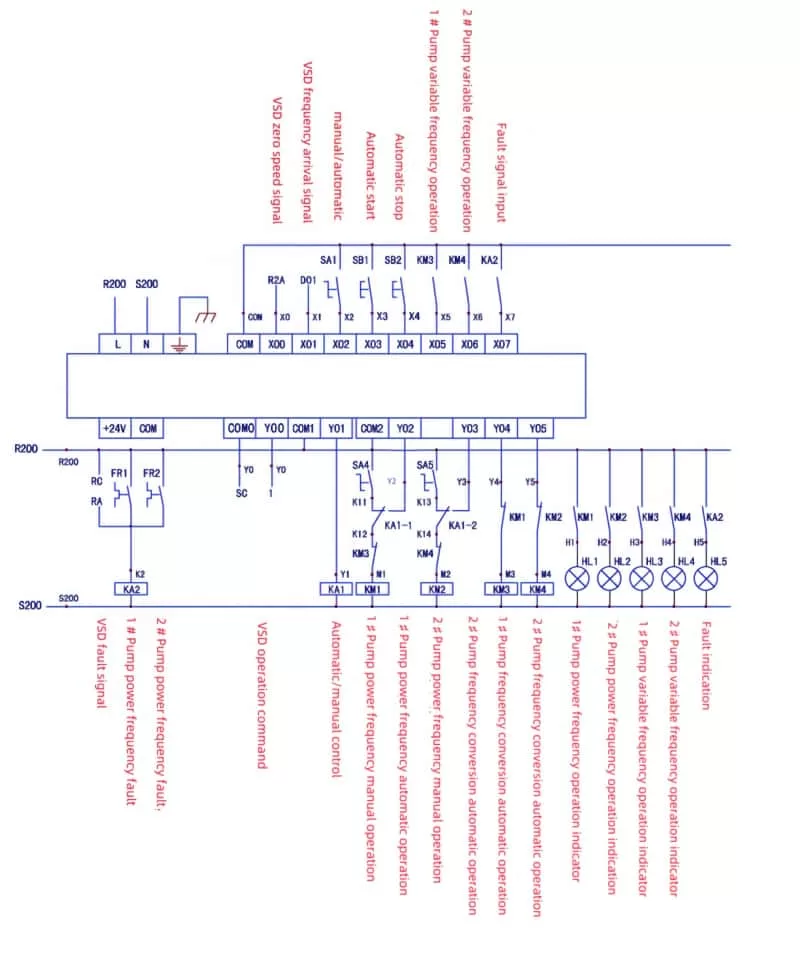
Mitsubishi PLC Constant Pressure Water Supply Circuit Diagram

System Overview

The system primarily consists of a frequency converter, a PLC, and two water pumps. The control mechanism leverages the PID (Proportional-Integral-Derivative) and other related functions of the frequency converter, in conjunction with the PLC, to achieve automatic constant pressure water supply. Additionally, the system is equipped with an automatic/manual switching function, allowing manual control of the water pumps in case of a frequency converter fault.

Control Process

The control process of the system is as follows:

  1. Initial Start-Up: When the pipeline pressure drops below the set value, the frequency converter starts the first pump (#1 pump).
  2. Full Speed Operation: After running at full speed for a predetermined period, if the pipeline pressure still does not reach the set value, the PLC switches the #1 pump from frequency conversion to power frequency operation.
  3. Second Pump Activation: The frequency converter then starts the second pump (#2 pump), adjusting its speed based on the pipeline pressure to maintain constant pressure.
  4. Pump Switching: As water demand decreases and pipeline pressure increases, if the #2 pump’s speed drops to zero but the pipeline pressure remains high, the PLC stops the #1 pump operating at power frequency, allowing the #2 pump to maintain constant pressure.
  5. Cycle Continuation: When the pipeline pressure drops again, the #2 pump is switched to power frequency operation, and the frequency converter starts the #1 pump, adjusting its speed to maintain constant pressure. This cycle continues indefinitely.

Frequency Converter Settings

For the system to function correctly, the frequency converter must be configured with specific parameters:

  • Start/Stop Control: Set to operate on external terminals.
  • Parking Mode: Configured for free parking to avoid impact during frequency conversion/power frequency switching.
  • PID Mode: Enabled, with the pressure setting value entered via the AUX terminal and the feedback signal entering via the VIN terminal.
  • Control Terminals: Configured to output contact actions for frequency conversion faults, zero speed, and full speed.
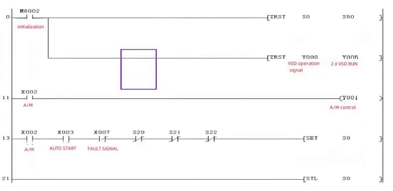
Mitsubishi PLC Constant Pressure Water Supply Program Diagram 1
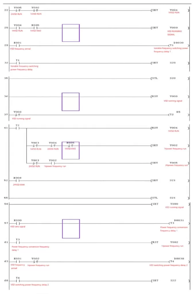
Mitsubishi PLC Constant Pressure Water Supply Program Diagram 2
Mitsubishi PLC Constant Pressure Water Supply Program Diagram 3
Mitsubishi PLC Constant Pressure Water Supply Program Diagram 4

PLC Control Wiring and Program

The PLC control wiring diagram shows the integration of fault signals from the water pumps and frequency converter, summarized through relay KA2. The manual/automatic switching is controlled by relay KA1, while the frequency conversion/power frequency operation is interlocked via contactor contacts for enhanced safety.

The PLC program is straightforward, consisting of four main steps (S20 to S23) that form a complete cycle. The switching time between frequency conversion and power frequency is adjustable via two potentiometers (D8030 and D8031) connected to the FX1S type PLC.

The program utilizes step instructions combined with set and reset commands. Step control begins with the STL instruction, and upon completion of all steps, a RET instruction returns the program to the starting step (S0). The SET command energizes the coil, while the RST command de-energizes it. The ZRST command is used for batch resetting multiple coils.

Technological Advancements and Alternative Solutions

As technology progresses, frequency converters are becoming more advanced, with some models capable of one-to-three or even one-to-six configurations. Automated instruments can also perform the PID function, allowing the frequency converter to work passively. In some setups, the frequency converter drives only one pump in a fixed manner, with the second pump directly switched to power frequency when needed. This approach, combined with timely pressure regulation by the frequency converter, results in more stable pipeline pressure.

Conclusion

The PLC-based variable frequency constant pressure water supply system with a one-to-two drive is a reliable and efficient solution for maintaining stable water pressure in pipeline networks. By leveraging the capabilities of PLCs and frequency converters, the system automatically adjusts pump operations to meet changing water demands. As technology continues to evolve, alternative solutions and configurations will emerge, offering even greater flexibility and efficiency in water supply management.

Posted on Leave a comment

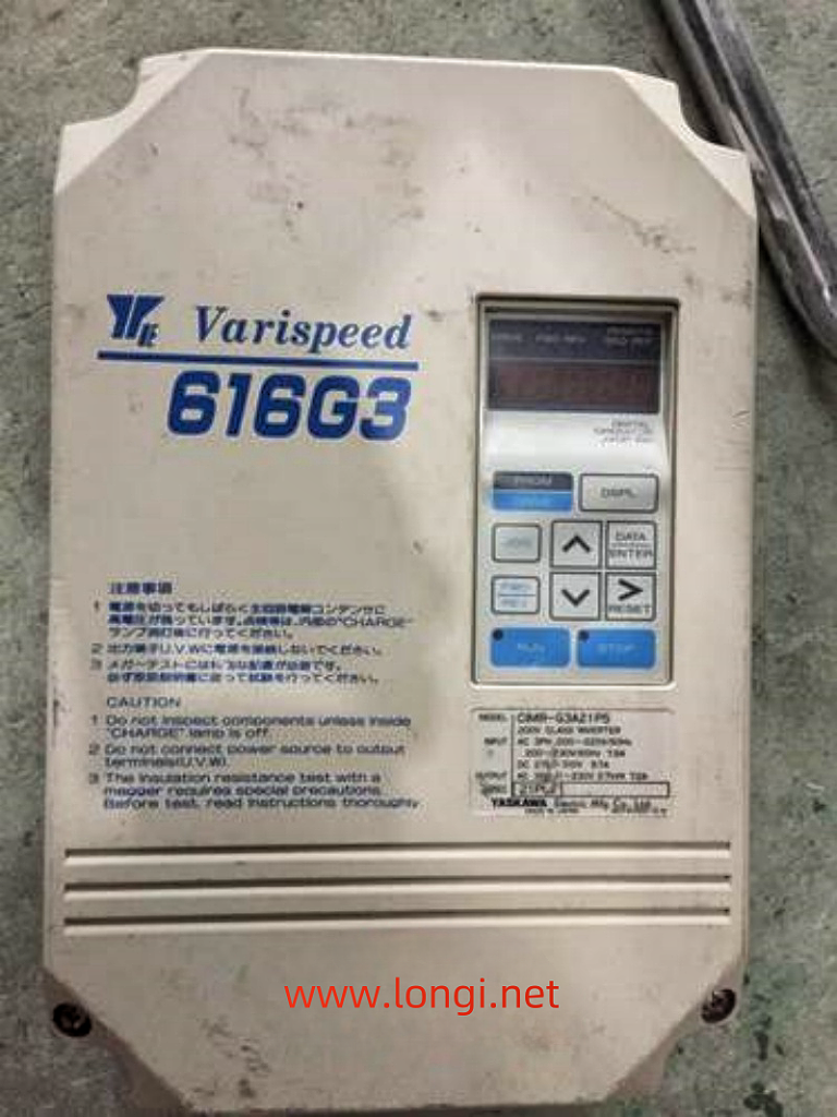
Repairing the Stubborn GF Fault in Yaskawa 616G3 55kW Frequency Converter

Repairing a frequency converter, especially one that reports a stubborn ground fault (GF), can be a challenging and frustrating task. Recently, I encountered such an issue with a Yaskawa 616G3 55kW frequency converter. Despite the common advice to replace the board, I delved deeper into the problem, determined to find a logical solution. This article outlines the step-by-step process I followed to diagnose and repair the GF fault without replacing any major components.

Initial Diagnosis and Background

The Yaskawa 616G3 frequency converter had been out of service for two to three years before it arrived at our repair department. Upon inspection, we found that two of the three-phase power input rectifier modules and two of the six inverter IGBT modules were damaged. The driver board had also suffered some component damage due to the module failure.

The GF fault typically indicates an issue with the drive circuit or the IGBT module itself, especially during the initial startup stage when the three-phase output voltage has not yet been established. Understanding the structure of the protection circuit helped narrow down the potential causes. The GF and OC (load-side short circuit) fault signals are fed directly to the CPU by the protection circuit of the driving circuit board.

Driver and Protection Circuits Inspection

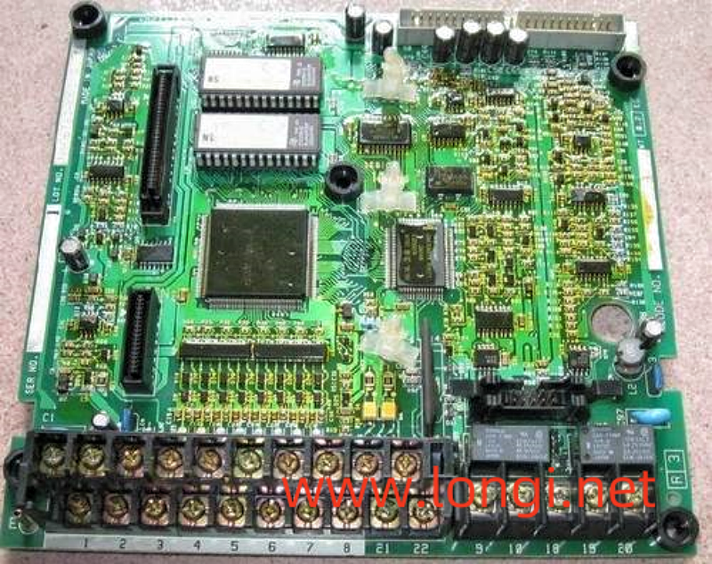
The driver circuit of the Yaskawa frequency converter includes six pulse signals from the CPU, isolated and amplified by six TLP250 ICs, and sent to the IGBT modules. Additionally, six TLP750 ICs form a module fault protection circuit, reporting GF and OC signals to the CPU. There are also three 2501 optocouplers responsible for detecting fuse status.

After disconnecting the driver board and CPU motherboard, I replaced the damaged components in the power amplifier circuit. The switch power supply and motherboard appeared to be functioning correctly. I manually cleared other potential faults, such as overvoltage, undervoltage, overheating, and fan issues, to ensure the drive circuit could output normal excitation pulses.

Addressing the FU Fault

During the initial tests, the circuit reported an FU (fuse) fault. After inspecting the relevant optocoupler components and circuit components, I found that the copper foil strip of the N lead was broken due to mold. This caused the fuse detection circuit to assume the fuse was broken. I repaired the moldy copper foil strip and retested the circuit, which resolved the FU fault.

Further Investigation and Component Replacement

With the FU fault resolved, I pressed the RUN button on the operation panel and measured the six pulses output by the drive circuit, all of which were normal. However, the GF fault persisted. I re-inspected the driver board, measuring all circuit components and short-circuiting the GF fault feedback optocoupler, but the GF fault still tripped.

Further investigation revealed a poor contact between a diode in the IGBT voltage drop detection circuit and the copper foil strip. I also found that the positive voltage of the W-phase transistor driver pulse was low, indicating an issue with the driver IC. After replacing the faulty A3320 IC, the output pulse amplitude returned to normal.

The Stubborn GF Fault

Despite repairing the identified issues, the GF fault still occurred during startup. I used the fault zone cutting method to narrow down the fault range, eventually finding that the IGBT driver circuit (protection circuit) of the U-arm was prone to reporting the GF fault. A diode with a poor contact was identified and replaced.

However, even after these repairs, the GF fault persisted. I then conducted a series of tests, including short-circuiting the module detection circuit’s transistors to relieve the fault protection function. During these tests, I observed an abnormal phenomenon: the series-connected light bulb lit up with high brightness after the start signal was activated, indicating a potential issue with the IGBT modules or driving circuit.

Discovering the Common Cause

After ruling out issues with the driving circuit and modules, I focused on the common factors that could affect all six protection circuits. I noticed that the leads of the capacitor bank, which were longer due to the repair setup, could be introducing inductance into the circuit. This inductance could generate induced electromotive force and current, interfering with the module fault detection circuit.

To test this hypothesis, I formally installed the machine, limiting the lead inductance of the capacitor bank within the allowable value. After the installation, the Yaskawa frequency converter operated normally without tripping the stubborn GF fault.

Conclusion

Repairing the GF fault in the Yaskawa 616G3 55kW frequency converter was a challenging but rewarding experience. By thoroughly understanding the protection circuit and methodically diagnosing each potential issue, I was able to repair the machine without replacing any major components. The key to solving the stubborn GF fault was identifying the common cause—inductance in the capacitor bank leads—and addressing it through proper installation.

This case study highlights the importance of logical reasoning and thorough investigation in repairing electronic equipment. It also demonstrates that, with patience and persistence, even stubborn faults can be resolved without resorting to costly board replacements.

Posted on Leave a comment

Omron PLC Switch Power Supply: Understanding and Maintenance Guide

Omron, a leading Japanese brand in the field of Programmable Logic Controllers (PLCs), holds a significant market share in mainland China. Given its widespread application in industrial control systems, understanding the maintenance of Omron PLCs, particularly their switching power supplies, is crucial for ensuring operational efficiency and minimizing downtime. This article delves into the maintenance process of Omron PLC switch power supplies, focusing on common faults, diagnosis, and repair methods.

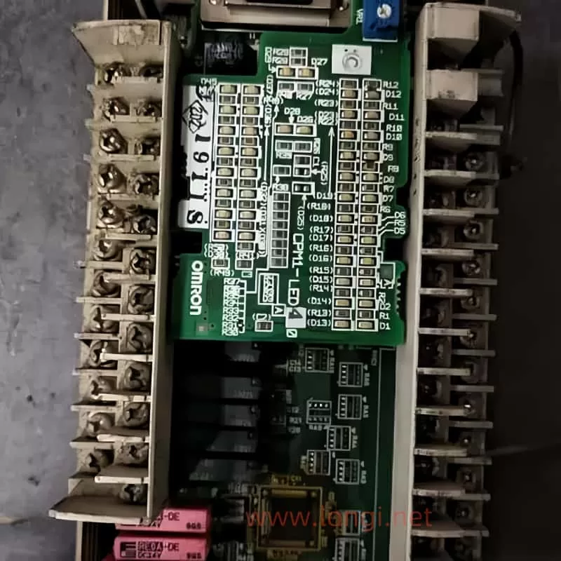
Internal physical diagram of Omron PLC

The Importance of Switch Power Supplies in Omron PLCs

The switch power supply is a critical component of any PLC, including Omron models. It converts the incoming AC power into the DC voltage required to operate the PLC’s internal circuitry. A faulty power supply can lead to a variety of issues, ranging from the PLC not powering on at all to intermittent operation and potential damage to other components.

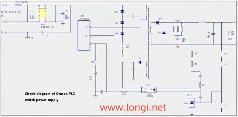
Schematic diagram of Moron PLC switch power supply circuit

Common Faults in Omron PLC Switch Power Supplies

One of the most common issues encountered with Omron PLCs not displaying after being powered on is a faulty switch power supply. Fortunately, these power supplies are often relatively simple in design, making them easier to diagnose and repair. Based on extensive repair experience, there are three primary components that commonly fail:

  1. F11 Fuse: This fuse is designed to protect the circuit from overcurrent situations. If the fuse blows, it indicates that there has been an excessive current draw, possibly due to a short circuit or component failure.
  2. IC11 Power Module: The power module is the heart of the switch power supply, responsible for converting AC to DC. It can fail due to age, overheating, or surge currents.
  3. C12 Electrolytic Capacitor: Often overlooked, the C12 capacitor plays a crucial role in stabilizing the power supply. Over time, the electrolyte inside the capacitor can evaporate, leading to a loss of capacity. This loss of capacity can cause surge currents that the power module cannot handle, leading to its failure.

Diagnosing and Repairing Omron PLC Switch Power Supplies

When faced with a non-responsive Omron PLC, the first step is to check the switch power supply. Here’s a step-by-step guide to diagnosing and repairing common faults:

  1. Visual Inspection: Start by visually inspecting the power supply for any signs of damage or burnout. Check the fuse (F11) to see if it has blown.
  2. Measure Component Values:
    • Fuse (F11): Use a multimeter to check for continuity. If the fuse is open (no continuity), it needs to be replaced.
    • Power Module (IC11): Measure the voltage across the module’s input and output terminals. If the module is faulty, you may find abnormal voltage readings or no voltage at all.
    • Electrolytic Capacitor (C12): This is where many technicians make a mistake. Even if the capacitor looks normal and shows no signs of short-circuiting when measured in-circuit, it may have lost significant capacity. Remove the capacitor and measure its capacitance. A healthy capacitor should have a value close to its rated capacity. If it’s significantly lower, replace it.
  3. Repair and Replacement:
    • Replace any blown fuses (F11) with a fuse of the same rating.
    • If the power module (IC11) is faulty, replace it with an exact match. Ensure that the new module’s specifications (such as voltage, current, and frequency) match the original.
    • When replacing the electrolytic capacitor (C12), choose a high-quality replacement with the same or higher capacitance and voltage rating. Be sure to install it away from heat sources to prevent future capacity loss.
  4. Testing: After making repairs, test the power supply without load first. If it powers on without issue, gradually add load to ensure stability. Listen for any abnormal sounds, such as a “snap,” which may indicate a component failure.
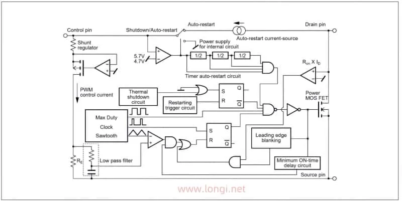
Internal schematic diagram of MIP0223SC power module

Understanding the IC11 MIP0223SC Power Module

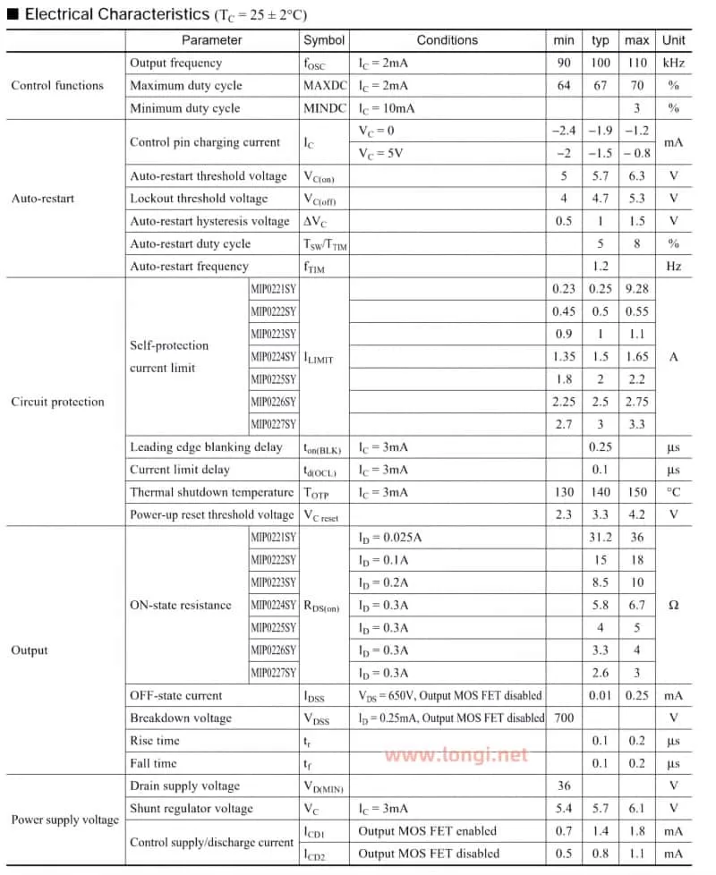
To effectively maintain the switch power supply, it’s essential to understand the key components, especially the IC11 MIP0223SC power module. While a detailed understanding of all the parameters and unit circuits is not necessary, familiarity with the module’s basic functions and pin connections is crucial. Refer to the schematic data table for key parameters such as power supply voltage, oscillation frequency, working current, and power capacity. This information will guide you in troubleshooting and ensuring compatibility when replacing components.

MIP0223SC Power Module Parameter Table

Conclusion

Maintaining Omron PLC switch power supplies doesn’t have to be a daunting task. By understanding the common faults, performing thorough diagnostics, and using high-quality replacement components, you can keep your PLCs running smoothly and minimize downtime. Remember, the key to successful maintenance is not just replacing faulty parts but also identifying the root causes of failures, such as the loss of capacity in electrolytic capacitors, and addressing them proactively. With this guide, you’ll be well-equipped to handle any issues that arise with Omron PLC switch power supplies, ensuring the reliability and longevity of your industrial control systems.

Posted on Leave a comment

Mitsubishi VSD F700-A700 Power Driver Board Circuit Diagram and MCU and Optocoupler Specification Confirmation

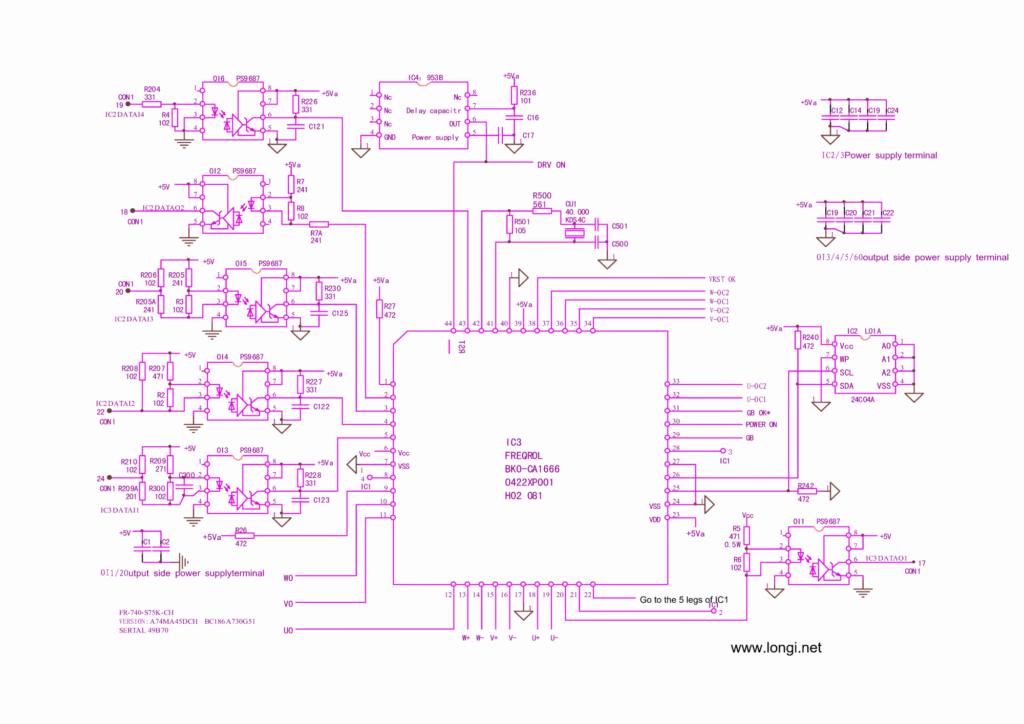
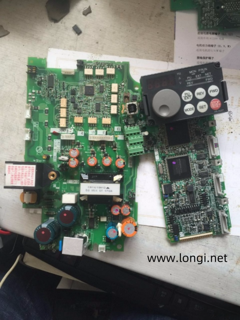
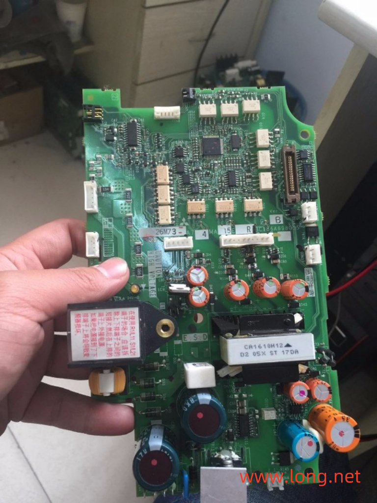
There is a separate MCU and six communication optocouplers OI1~OI6 on the power drive board of Mitsubishi F700 (F740, F720) and A700 (A740, A720) frequency converters. Their specifications look a bit mysterious and may cause confusion during maintenance. The relevant circuit diagram will be drawn below, and a simple functional analysis of the MCU and optocoupler will be conducted to reduce the difficulty of repairing and changing the frequency converter.

OI6:
Responsible for transmitting the operation and shutdown instructions of the motherboard MCU, with instructions in the form of 1 and 0 levels. The 19 pin of CON1 is a 5V high level, which is a running command. The output side of OI1 becomes 0V, and the local MCU can send 6 pulse signals such as U+~W – to the driving circuit; The 19 pin of CON1 is at 0V low voltage level, and the motherboard MCU sends a shutdown command (if it becomes low during operation, the OI1 output side becomes 5V, which is an overload fault shutdown command). The messenger of the motherboard MCU sends running and stopping commands to the local MCU in the form of DC
The 0 and 1 levels of opening and closing quantities.

OI2:
The serial data returned by the local MCU and motherboard MCU is in the form of rectangular wave pulses. Start working immediately after powering on.
The communicator between the local MCU and the motherboard MCU, signal direction: transmitted locally to the motherboard MCU.

OI5:
The communicator between the motherboard MCU and the local MCU, signal direction: The motherboard MCU issues instructions to the local MCU
MCU. The signal form is serial data, and the test is a rectangular pulse train. Start working immediately after powering on.

OI4:
The main board MCU sends switching instructions to the local MCU, and under normal conditions (running and stopping), the output terminal 6 pins are 0V. When it reaches 5V high level, an E7 code (meaning CPU error) is reported. Is its task to confirm the working status of the motherboard MCU?

OI3:
The communication personnel between the motherboard MCU and the local MCU, signal direction: The motherboard MCU issues instructions to the local MCU. The input signal is in the form of serial data (synchronous clock signal?), but due to the capacitance integration effect at pins 5 and 6, a triangular wave of 760kHz is measured. Start working immediately after powering on.

OI1:
The communication personnel between the local MCU and the motherboard MCU, signal direction: The local MCU reports the fault situation to the motherboard MCU. Signal form 0, 1 switch quantity DC voltage. The shutdown status between pins 5 and 6 of the output terminal is 0V, which changes to a high level of 5V after operation. When there is a fault, it changes to 0V and displays the alarm code EOC1.
As a module fault reporter, he reports the fault situation to the motherboard MCU.

Posted on Leave a comment

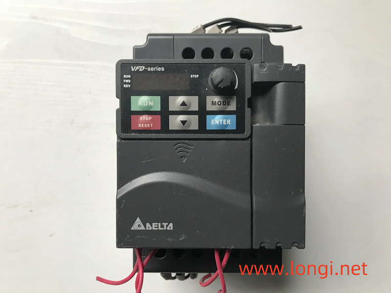
How to handle the password lock of VFD-E Delta VFD converter?

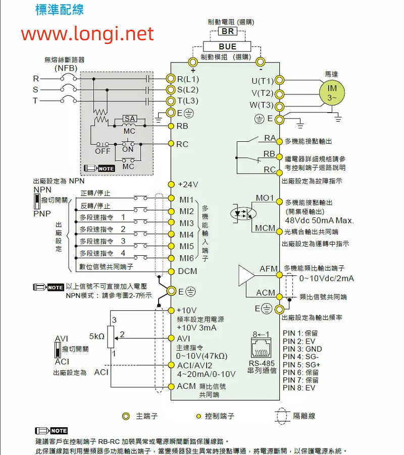
I helped a friend debug a Delta VFD-E frequency converter on site, but due to a damaged panel, I couldn’t operate it after purchasing a panel provided by a friend. This friend went to the site and adjusted it all morning, but the frequency converter still couldn’t run. When I arrived at the site, I found that the parameters couldn’t be changed. The machine parameters 00.08 and 00.09 are for protecting password input and protection password setting, respectively. When the 00.09 parameter is assigned a value of 1, it indicates that the parameter has been locked by divisor. The correct password needs to be entered from parameter 0.08. After the value in parameter 00.09 becomes 0, all parameters can be operated. However, before changing the panel, the machine is said to be functional. In theory, You can use it by replacing the good panel. It’s impossible to set the password on your own after replacing the panel. Someone must have accidentally changed the 00.08 parameter! I don’t know the password! The factory personnel called to inquire about multiple people, but I’m not sure if there’s anything else they can do. Should we withdraw now? The machine is not running yet. It cannot be produced. We need to try to make the machine run. Although the parameters cannot be modified, they can be called up for monitoring. Therefore, we can call up parameters 02-00 and 02-21, which are frequency commands and operation commands. Both parameters have a value of 1, which is controlled by terminal start/stop and external potentiometer. The start/stop of the machine was originally wired through terminals, and a torsion switch has been connected to terminals M11 and DCM for starting, Stop the control. Find a 1k potentiometer, connect terminals+10VAV1 and ACM, power on and test the machine. The machine is running! The manufacturer’s personnel are very happy and eager to ship. The operators also feel that using a potentiometer for speed regulation is even more convenient than panel speed regulation.

After multiple efforts, we finally obtained the super password for this frequency converter. Parameter 008 is a password item, and entering the 8333 super password can unlock it. If you encounter similar problems in the future, you can unlock it through the super password and then operate it without changing the control method to complete the task.

Posted on Leave a comment

Simplified Debugging Guide for Siemens 400 Series (420/430/440) VFD Drives

Simplified Debugging Guide for Siemens 400 Series (420/430/440) VFD Drives

Debugging a Siemens 400 series Variable Frequency Drive (VFD), specifically models 420, 430, and 440, can initially seem daunting due to the multitude of parameters and unfamiliar symbols on the operation panel. However, with a structured approach, even newcomers can quickly master the basics and get these drives running efficiently. This guide will outline a straightforward method for debugging, focusing on essential functions like start/stop control and frequency adjustment, along with some tips for PID operation and parameter adjustment.

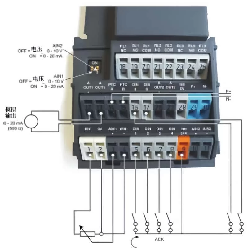
Terminal connections of the Siemens 400 Series (420/430/440) VFD Drives

Initial Setup and Terminal Connections

Before diving into the parameter settings, ensure that the terminal wires are properly connected. For basic operation, you’ll need to connect five wires:

  1. Start/Stop Switch: Connect between terminals 5 and 9.
  2. Potentiometer for Frequency Adjustment: Short-circuit terminals 2 and 4, then connect wires from terminals 1, 3, and 4 to the potentiometer, with terminal 3 connected to the center head.
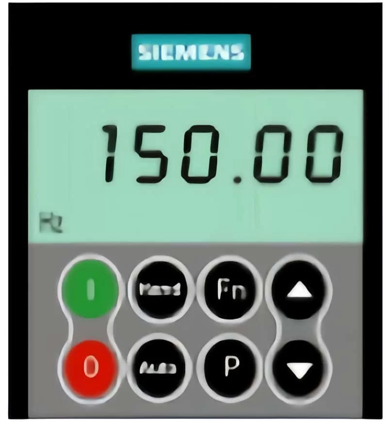
Operation Panel

Understanding Operation Panel Keys

The operation panel of the Siemens VFD is equipped with several keys that serve different functions:

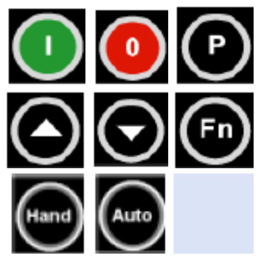
  • Start/Stop Keys: Marked as 1 and 0, these control the run and stop operations.
  • Parameter Adjustment Keys: The P key enters parameter adjustment mode, while the up and down arrows navigate through the parameters. The P key also confirms selections and writes values.
  • Data Display/Reset Key: Press for 2 seconds to view operating data. It also serves as a return key after parameter adjustment and a reset button for fault shutdown.
  • Control Mode Switch Keys: The “Hand” key enables operation via the panel, while the “Auto” key switches to terminal control.
Operation Panel Keys

Quick Start Guide for New Machines

For newly manufactured machines, you can bypass extensive parameter adjustments by understanding the basic button functions and ensuring correct terminal connections. However, for used machines, it’s often simplest to initialize all parameters to their factory settings:

  • Set P0010=30
  • Set P0970=1

After entering these values, the drive will reset, which may take about three minutes.

Parameter access level

PID Operation Adjustment (440 Model)

For PID control, you’ll need to configure specific parameters:

  • P2200=1: Enables PID function, disables conventional frequency settings.
  • P2253: Selects the PID setting signal source (e.g., P2253=755 for analog input 1).
  • P2264: Selects the PID feedback signal source.

Multi-machine operations, such as PID one variable frequency with three power frequencies, require detailed adjustments according to the manual.

Tips for Parameter Adjustment

  • To access PID parameters, set P003=3 for expert-level parameters.
  • Adjust P004 to change specific parameter settings, such as P004=10 for frequency setting values.
  • Define digital terminal functions with P700=2 for digital input control.

Shortcuts and Precautions

  • Fault Reset: Set a terminal to 12 for reverse operation and fault reset.
  • Fixed Frequency Operation: Set a terminal to 15 for multi-stage speed control. Adjust P1000=33 for analog signal plus fixed frequency.
  • V/F Curve Adjustment: Customize the V/F curve with P1300 based on the load type (e.g., constant torque, variable torque).
parameter level

Inertial (Free) Parking Control

For applications requiring inertial parking, set P701=1 for forward start/stop and P702=3 for inertial parking. Connect terminals 5 and 6 in parallel and control via terminal 9.

Special Considerations for High-Power Motors

When starting high-power motors, Siemens VFDs may output a certain excitation current to magnetize the stator winding before the motor starts. This is not a malfunction but a feature to reduce starting current.

Conclusion

By following this structured approach, even those new to Siemens 400 series VFDs can quickly become proficient in their operation and debugging. Remember to consult the manual for detailed parameter descriptions and always initialize parameters for used machines to ensure a smooth start. With a basic understanding of the operation panel, terminal connections, and key parameters, you’ll be well-equipped to handle a variety of applications and control requirements.

Posted on Leave a comment

Different scenarios of “GF” ground fault are reflected in the maintenance of Yaskawa 616G3 VSD drive

The power on display is normal. Start the operation, that is, jump “GF” fault, but it does not run or shows no signs of running. I quickly jumped over the ground fault. The “GF” fault at this time is equivalent to the “OC” fault of other frequency converters, and the fault is located in the inverter module or driving circuit. At the moment when the CPU sends the trigger pulse, it detects an abnormally large pressure drop in a certain IGBT tube and fails to open it normally during the arrival of the trigger pulse. In fact, during this time, the current transformer of the frequency converter did not detect the output current signal at all. At this point, the “GF” fault signal is fed back to the CPU by the module fault detection circuit of the driving circuit. (This fault action was determined by testing.)

Repair and inspection: Check the quality of the inverter block, especially the inspection of the trigger terminal cannot be ignored; Check the driving circuit, especially the filter capacitor of the driving power supply, and measure whether the driving voltage is normal, but whether there is a certain current driving ability.

  1. Jumping “GF” fault during operation is a fault reported by the current detection circuit. There are two aspects that need to be distinguished. On the one hand, it is a normal fault shutdown action, where the current transformer detects abnormal overcurrent and reports to the CPU to implement fault shutdown protection; On the one hand, the subsequent current signal processing circuit of the current transformer is faulty, such as the variable value of the resistor element, which causes the “GF” fault voltage setting point to drift, resulting in false alarm faults. The signal from the current transformer is processed through an operational amplifier, sent to the CPU for current display and fault alarm processing, and sent to a voltage comparator, reporting a “GF” fault. (Note: The subsequent circuit of this current transformer was not thoroughly investigated, but it was inferred from numerous fault phenomena and is for reference only.)
    Repair and inspection: When it is confirmed to be a false alarm fault, it is not necessarily necessary to replace the motherboard for repair. Detailed inspection of the current transformer and its subsequent circuits should be able to repair it.
  2. By the way, when an overcurrent fault is reported during operation for OL1, OL2, and OL3, it is detected by the current transformer and subsequent current signal processing circuit during operation. After sending the current signal to the CPU, it is judged, frequency reduced, and processed to report the overcurrent fault signal. For sudden abnormal overcurrent faults, module damage, or abnormal driving circuit faults, the driving circuit will directly feedback to the CPU, and the CPU will report an OC fault.

This suggests different treatments for undervoltage and overvoltage faults in other frequency converters. For undervoltage, after power on, it is detected and delayed for at least 5 seconds before reporting. Started 5 seconds ago and was able to run, but then experienced an undervoltage fault; For overvoltage faults, the fault will trip immediately after power on and operation is prohibited. It can be seen that designers attach greater importance to overvoltage faults than undervoltage faults. It can also be known that overvoltage faults pose greater harm to frequency converters than undervoltage faults do to frequency converters. And the handling of different fault alarms by designers can also be understood.

Posted on Leave a comment

Key Considerations for Selecting and Using Variable Frequency Drives (VFDs)

Variable Frequency Drives (VFDs), also known as frequency converters, are essential devices in modern industrial and commercial applications, providing precise control over motor speed and torque. However, their effective utilization requires a thorough understanding of their operational nuances and precautions. This article delves into the critical aspects of selecting and using VFDs to ensure optimal performance and longevity.

Operational Modes and Control Mechanisms

When integrating a VFD into your system, it’s crucial to understand its operational mode. Some VFDs cannot be directly controlled via the panel for start/stop operations. Instead, they require control terminals to be connected in either the forward or reverse direction. Essentially, the motor’s direction must be predetermined through these terminals before the panel can control the start/stop functions. This setup ensures seamless operational control and prevents any potential misdirections or malfunctions.

For applications involving pole-changing motors, it’s advisable to connect the VFD according to the high-speed connection method initially and then adjust the speed as required. If the motor needs to operate at lower speeds, a medium-speed connection can also be utilized. This flexibility allows for optimized performance across various speed ranges.

Voltage and Connection Considerations

Low-power motors with three-phase angle connections of 220V can be connected in a star configuration when using a VFD. This setup enables direct driving by a 380V VFD, maintaining the motor’s output power without the need to reduce the VFD’s output voltage. This approach is superior in terms of efficiency and performance.

In scenarios where the power supply capacity significantly exceeds the VFD’s capacity, harmonic components in the input current may increase. This can lead to increased losses and potential damage to rectifier diodes and capacitors. To mitigate these effects, installing input reactors is recommended. These devices improve the power factor, reduce the impact of three-phase current imbalance, and provide a degree of lightning protection.

Enhancing Performance and Reducing Interference

Installing an output reactor can further enhance the system’s performance by improving the current waveform, reducing motor operating noise, and boosting energy-saving effects. In cases where VFD-generated interference affects on-site instruments, lowering the carrier frequency can often resolve or mitigate the issue. For high-power motors, a moderate reduction in carrier frequency is advisable, particularly when starting difficulties arise. Adjusting the starting curve by shortening it and reducing the carrier frequency can facilitate smoother starts.

Motors with high operating inertia and specific stopping time requirements may need the addition of braking units and braking resistors. Proper adjustment of these parameters ensures smooth deceleration and stopping. When driving submersible pump motors, selecting a VFD with a higher power rating is recommended due to their larger rated current compared to ordinary motors.

Shutdown Methods and Torque Boosting

In constant pressure water supply systems using a single VFD, a deceleration shutdown method, akin to soft shutdown, can prevent the water hammer effect. However, in systems with one-to-several configurations or power frequency bypasses, a free shutdown method is preferable to avoid contactor tripping and potential damage to the VFD module from the motor’s back electromotive force.

Torque boosting parameters must be carefully set and tested. Excessive torque boosting at low frequencies can cause motor windings to become overexcited, leading to magnetic saturation and a significant torque reduction. This can result in the motor emitting a buzzing sound without rotating, accompanied by a substantial increase in output current, potentially triggering OC faults. Reducing the torque boosting parameter often resolves this issue.

Parameter Protection and Maintenance

If parameters cannot be modified, it may indicate that they are protected or restricted. In such cases, adjusting relevant parameters to disable protection or performing parameter initialization can be necessary. In dusty environments, regular cleaning and dust prevention measures are crucial to maintain VFD performance.

When wiring low-power VFDs (below 1kW), it’s vital to check the voltage level label on the nameplate to ensure correct connection. Misconnecting a 220V VFD to a three-phase 380V supply can cause immediate damage. Manufacturers should clearly mark terminal connections to prevent such mistakes.

The VFD’s power supply should be introduced using an air circuit breaker, with contactors used solely for protection, not for start/stop control. Using contactors for this purpose can shorten the lifespan of the VFD’s energy storage capacitor and impact the rectifier module.

Grounding, Lightning Protection, and Motor Compatibility

Signal shielding wires should be grounded at one end only to avoid circulating currents and interference. In lightning-prone areas, installing lightning arresters near the VFD’s incoming line and ensuring proper grounding is essential.

VFDs are designed based on the rated current of a four-pole motor. When used with motors with more poles, the VFD’s power capacity must be increased to accommodate the higher rated current.

Due to high-frequency leakage current in the VFD’s output circuit, both the motor and control cabinet casings must be reliably grounded. Standard circuit breakers with leakage protection should not be used as power switches for VFDs. If leakage protection is necessary, specialized switches for VFDs or isolation transformers should be used to prevent tripping.

Conclusion

In conclusion, selecting and using VFDs requires a comprehensive understanding of their operational characteristics and precautions. Proper connection, voltage management, interference reduction, parameter setting, and maintenance are critical for ensuring optimal performance, longevity, and safety. By adhering to these guidelines, industries can harness the full potential of VFDs, enhancing motor control, efficiency, and reliability in diverse applications.