Posted on Leave a comment

Principle of Frequency Converter (VFD)

A frequency converter, as the name suggests, is a device that can change the frequency. It is just an AC power supply that can adjust the frequency and voltage output, mainly used for speed regulation of asynchronous motors. Before the emergence of frequency converters, asynchronous motor speed regulation was very troublesome because the speed and torque were not in a straight line, such as using a slip head for speed regulation or simply reducing voltage for speed regulation, which had unsatisfactory results. According to the speed formula of a three-phase asynchronous motor, the speed n=60 * f/p (1-s), where p is the logarithm of poles, s is the slip rate, and f is the frequency of the power supply. As long as a frequency controllable AC power supply can be output, the speed of the three-phase asynchronous motor can be smoothly changed, which is the fundamental principle of frequency converter operation.

However, the three-phase AC power supply provided by power plants is a sine wave with a difference of 120 ° and a frequency of 50Hz. Before the invention of power electronic devices, it was almost impossible to change the frequency of this power supply. Therefore, the invention of AC motors has been almost 100 years without a good speed control device.

Later, high-power devices such as thyristors, GTR transistors, and IGBT transistors were invented at the end of the last century, and the embedded technology of single-chip microcontrollers became increasingly mature. People found the basic method for asynchronous motor speed regulation. That is to first rectify the three-phase AC voltage into fluctuating DC through diodes or thyristors, and then use capacitors to filter and stabilize it into stable DC. Six IGBT tubes are used to form an inverter circuit. The microcontroller uses PWM chopping to output a series of variable pulse width square waves, which are used to simulate the equivalent effect of variable frequency AC and achieve the goal of controlling motor speed.

It can be imagined that any curve can use many straight line segments to segment and simulate links. The more straight line segments used for simulation, the more accurate the curve can be described. This is actually the concept of calculus in mathematics.

Although a sine wave may seem complex, it can also be simulated and equivalent using many square waves. If a square wave with equal amplitude and variable width is output, and the area of the square wave is equal to the corresponding sine wave area, its effect will be equivalent to the working effect of the sine wave. By controlling the working cycle, the frequency of the output power can be changed, which is called PWM control, Because IGBT switches can achieve very high-speed switching functions, such as having a frequency of tens of K, the output square waves are sufficient, and the simulated sine wave effect is relatively good.

However, changing the frequency of the motor light is not enough, and the voltage should also be adjusted accordingly, otherwise it may cause the motor to work abnormally, such as severe heating and burning. The main reason is that the iron core of the motor is nonlinear, requiring that the voltage also changes when the power frequency changes, in order to control the main magnetic flux to remain constant.
Because: main magnetic flux ≈ motor voltage ÷ (4.44 * frequency * number of electronic winding turns)
Therefore, during frequency modulation, the motor voltage should also change with the frequency, so that the main magnetic flux can remain unchanged and avoid magnetic flux saturation or working in a weak magnetic state.

Posted on Leave a comment

Testing Method for Offline Operation of Mitsubishi MR-J3 Servo Driver Maintenance Board

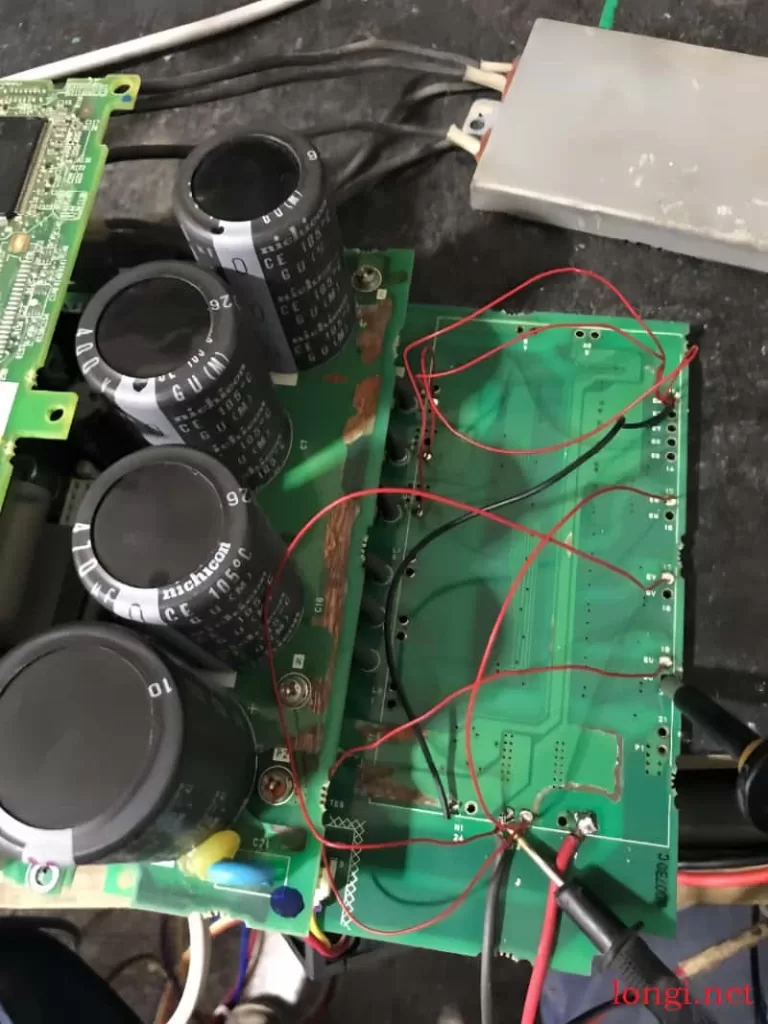
When repairing Mitsubishi servo drives, encountering damaged modules is common. After repairing such modules, it’s crucial to test the drive board’s output function offline before reinstallation. This article provides a detailed guide for testing a repaired Mitsubishi MR-J3-350A/3.5KW servo module.

Mitsubishi Servo MR-J3 Circuit Board Maintenance Test Diagram

Preparation for Offline Testing:

  1. Power Connection: Connect 300V DC voltage to power boards P2 and N to avoid E9 fault after power-on.
  2. Module Pad Hole Shielding:
    • Connect the 10 pins of the module pad hole to N.
    • Connect pad holes U, V, W to N to prevent AL24 fault.
    • Connect pad holes EV, EU, EW (upper axle drive trigger) to N.

Parameter Setting Before Running:

  1. Change PA01: Set PA01 to 0002.
  2. Change PD01: Set PD01 to 0000.
  3. Power Board Connection: Connect P and D on the power board.
  4. Additional Power Board Connections: Connect L1 to L11 and L2 to L12 on the power board.
    • If PD parameters are not visible, change PA19 to 000C and power on again.
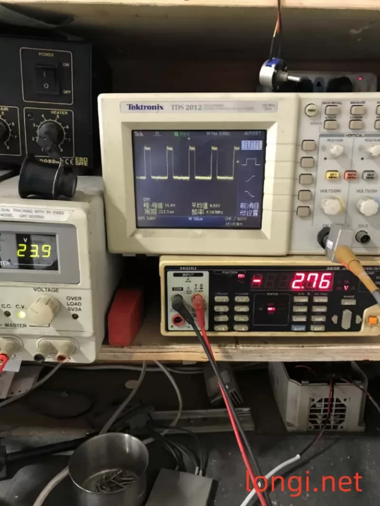
Mitsubishi servo MR-J3 drive circuit actual pulse state

Testing Process:

  • After following the above steps, power on and run the servo to test its 6-way waveform.
  • During parameter waveform testing, manually rotate the motor shaft to observe changes in pulse width and phase in the waveform. Note that this machine does not have a static cut-off negative voltage.

By following this comprehensive guide, you can effectively test the offline operation of a repaired Mitsubishi MR-J3 servo driver maintenance board, ensuring its functionality before reinstallation.

Posted on Leave a comment

Hello,Welcome To Longi!

As a professional company engaged in the sales and services of second-hand industrial control products, we are committed to providing high-quality and performance-oriented second-hand industrial control products to help customers improve production efficiency and reduce costs. The company was founded in 2000 and has gradually become a leading supplier of second-hand industrial control products in the industry through years of development.

Our product range is diverse, including second-hand frequency converters, PLCs, servo drivers, servo motors, industrial touch screens, instruments and meters. These products have undergone strict selection and testing to ensure that their performance and reliability meet the expectations of customers. We believe that these products will be able to meet your various needs and bring huge value to your industrial automation process.

In terms of technical services, we promise to provide customers with comprehensive engineering technical services. Whether you encounter any problems in the process of purchasing products or technical difficulties during operation, we will provide you with timely and professional support. Our technical team will provide you with the most appropriate solution based on your specific situation to ensure the smooth implementation of your project.

To ensure the reliable quality of the products purchased by customers, we provide a three-month warranty service. During the warranty period, if the product has a quality problem, we will provide free maintenance or replacement services for you. Our warranty service aims to allow customers to purchase and use with confidence, making your purchasing experience more pleasant.

If you have any questions or needs about our products or services, please feel free to contact us. You can contact us through telephone, email or visiting our office address. We will serve you wholeheartedly and look forward to cooperating with you.

In conclusion, as a professional second-hand industrial control product company, we use high-quality products, perfect services, and reliable warranties to accompany your industrial automation process. We believe that cooperating with us will be a wise choice for you, and we will do our best to help you achieve your business goals.

Posted on Leave a comment

Method of changing IP and station name using BOP panel for Siemens VSD G120 series

The Siemens G120 series frequency converters basically support communication control, such as Profibus and profinet protocols. When it comes to modifying addresses and station names, they are usually rewritten using software such as TIA and STARTER, or modified through the super panel IOP-2. However, the manual does not mention how to modify these parameters through the BOP panel. After practical exploration, I found that the BOP panel can also modify these parameters, The method is as follows:

1、 The G120C PN type frequency converter uses profinet communication, but it can be started, stopped, and adjusted using the manual function (HAND/AUTO) of the panel, which can directly determine the quality of the frequency converter without passing through the network.

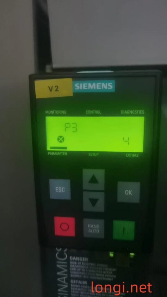
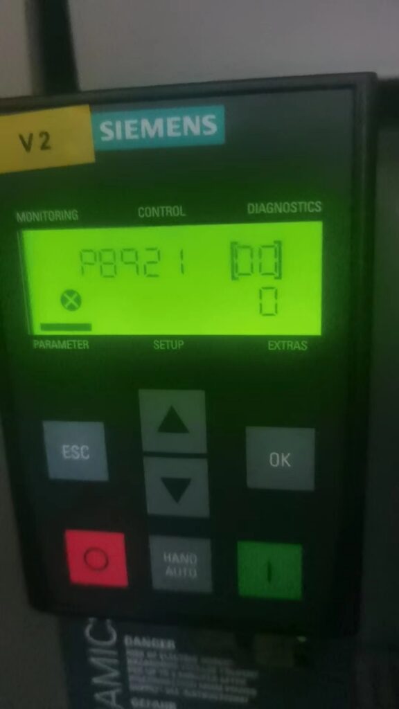
3、 P3 is set to 4 first, and the station name P8920 can also be configured using a simple panel like BOP-2, but the following cannot be configured:
P8921—— r8931 IP Address
P8922—— r8932 Default gateway
P8923- r8933 subnet mask
P8924—— r8934 DHPC mode

4、 In practical use, it was found that as long as the station name P8920 (with a total of 240 subscripts, corresponding to a maximum of 240 values) is set, such as IND [000], IND [001], IND [002]… IND [239] is actually an ASII value, it can be connected to the profinet. The P8921-P8924 on the top should not be ignored, and the upper level should have the opportunity to assign them additional values.

5、 Method for changing P8920 parameters in BOP-2
A. P8920=0, all its subscripts ind [000] [001] [002] until the corresponding value of [239] must be set to 0. Remember to press the OK key every time you modify one;
B. P8925=3, press the OK key to delete all IP configurations;
C. Power off the frequency converter for at least 20 seconds;
D. Power on again and re-enter the corresponding station name value (ASII) in P8920, [000] – [239], usually using 8.
E. P8925=2, power off for more than 20 seconds;

6、 BOP-2 can directly upload data other than the station name P8920-P892, such as motor current and power, and then download it to a new frequency converter. However, the parameters of P8920 can only be manually inputted according to the above process. Remember to set p971=1 after debugging and save the parameters (automatically changing to 0 after successful saving), otherwise the parameters will be lost after power outage.