Introduction
Induction heaters use electromagnetic induction to convert electrical energy into heat energy and are widely used in metal heating, hardening, annealing, and other industrial processes. The MC Huikai induction heater is known for its fast heating speed, high efficiency, and ease of operation. This guide will provide a detailed overview of the MC Huikai induction heater’s key technical parameters, wiring methods, control parameters, and usage precautions to help users properly install, commission, and maintain the equipment.
I. Key Parameters of the MC Huikai Induction Heater
The performance of the MC Huikai induction heater is influenced by key parameters that directly impact its heating efficiency. Below are the main technical specifications of the device:
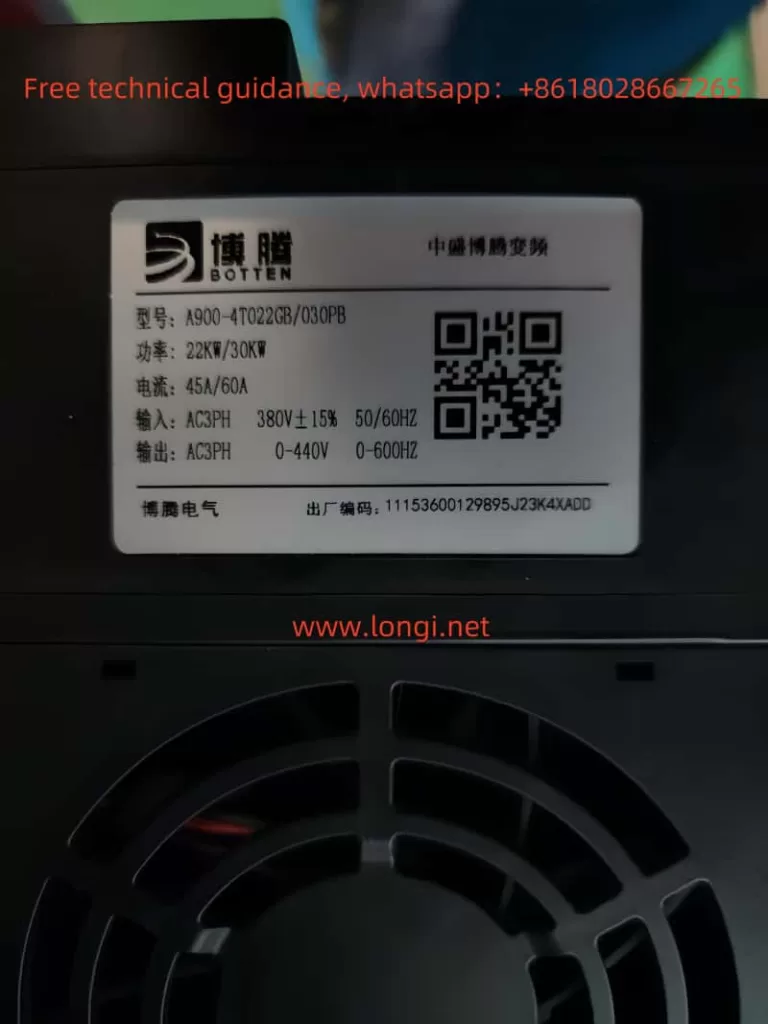
- Rated Power
The rated power of the induction heater typically ranges from 10kW to 500kW. Users can select the appropriate power based on the size and heating requirements of the workpiece. Higher power enables faster and more efficient heating, suitable for larger metal workpieces. - Operating Frequency
The operating frequency of the heater ranges from 20kHz to 80kHz. The frequency affects the heating depth and speed: lower frequencies are better for heating thicker materials, while higher frequencies are suited for quick heating of thinner materials. - Input Voltage
The input voltage is typically 380V or 660V, depending on the specific model and power requirements. It is essential to confirm the appropriate voltage rating for the equipment to ensure proper operation. - Heating Temperature Range
The heating temperature range of the MC Huikai induction heater generally extends from ambient temperature up to 1200°C, making it suitable for most metal heating applications. Some models may support even higher temperatures for specialized applications. - Cooling Method
The induction heater is equipped with a water cooling system to ensure proper heat dissipation and prevent overheating. The cooling water flow rate should be maintained within the recommended range for stable operation. - Control Method
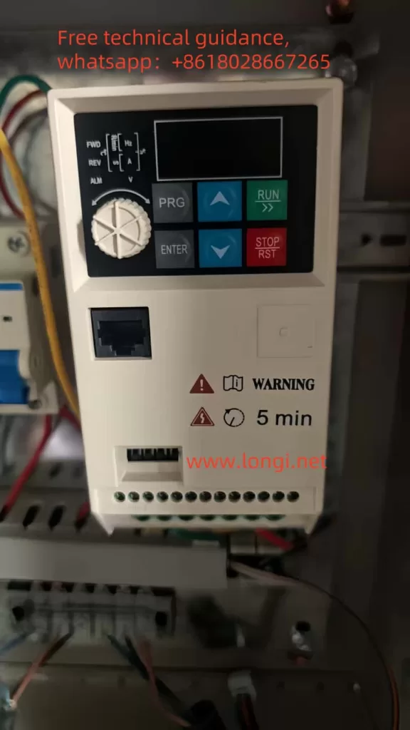
The system features digital control, allowing users to adjust parameters such as power and temperature via the control panel or external PLC, ensuring precise control of the heating process.
II. Device Parameter Settings and Command Source Selection
The MC Huikai induction heater offers several adjustable parameters for users to fine-tune based on specific heating requirements. Below are the common parameters and their functions:
- P0.00: Command Source Selection
This parameter selects the control command source for the heater. Common options include:- 0: External Control
When this option is selected, the operation of the heater is determined by an external controller or signal source, suitable for integration with other systems. - 1: Panel Control
In this mode, the heater is operated directly from the front panel, ideal for standalone use. - 2: RS485 Communication
This option allows remote control and monitoring through RS485 communication with other devices, such as PLCs or computers.
- 0: External Control
- P0.01: Power Adjustment Range
This parameter sets the power adjustment range of the heater. It can be adjusted to suit different heating needs:- 0: 0-100% Power Range
A general setting for most heating applications, where power can be adjusted from 0 to 100%. - 1: 0-50% Power Range
Suitable for applications requiring lower heating speeds or lower power settings.
- 0: 0-100% Power Range
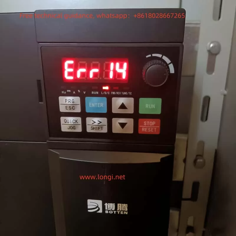
- P1.00: Overload Protection Setting
This parameter sets the overload protection threshold to prevent the heater from being damaged due to excessive load. The protection function can be enabled or disabled based on user needs:- 0: No Protection
Overload protection is disabled, and the heater may be damaged in case of overload. - 1: Enable Overload Protection
When enabled, the heater will automatically shut down if the load exceeds the set threshold.
- 0: No Protection
- P2.00: Temperature Control Mode Selection
This parameter selects the temperature control mode for the heater. The heating method is influenced by this setting:- 0: Open-loop Control
The heater does not monitor temperature changes in real-time and relies on preset power values for heating, suitable for applications that do not require precise temperature control. - 1: Closed-loop Control
In closed-loop control mode, the heater uses temperature sensors to monitor the workpiece’s temperature and adjusts power output accordingly to maintain accurate temperature control.
- 0: Open-loop Control
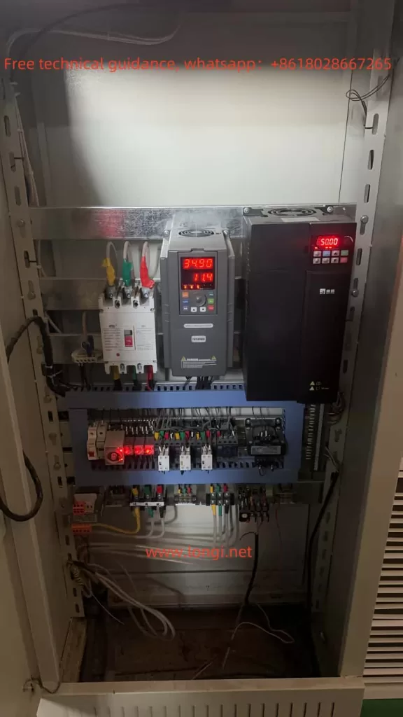
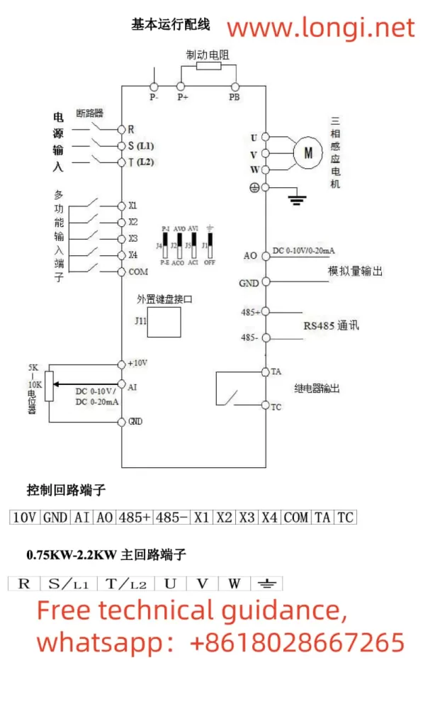
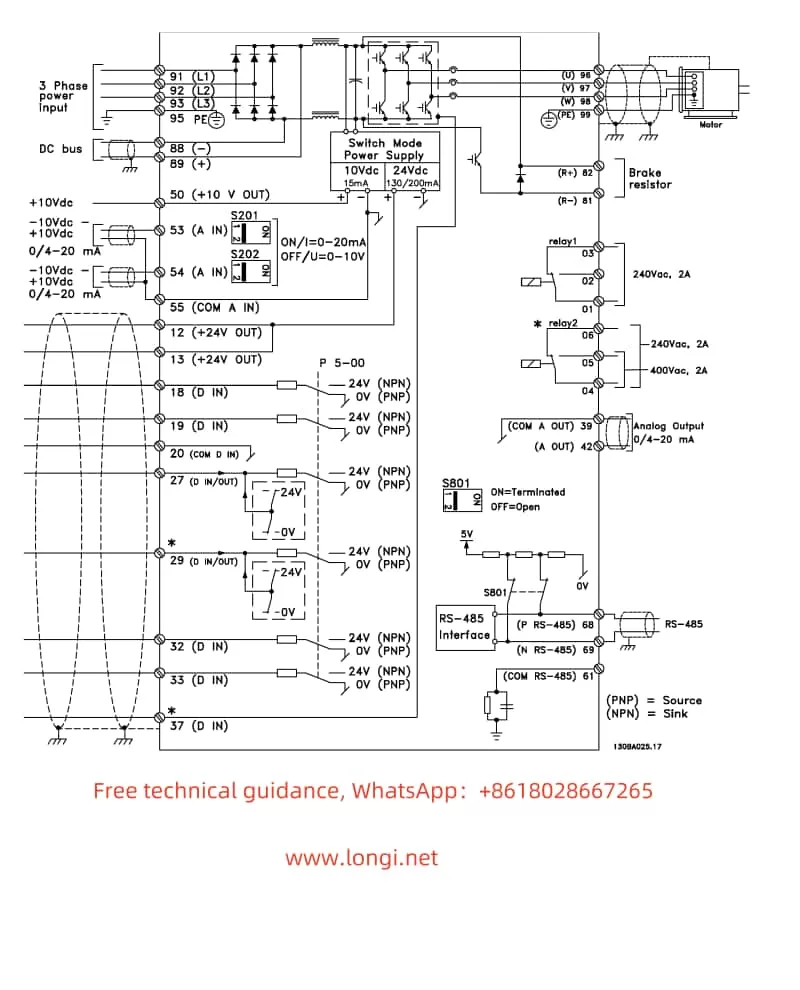
III. Wiring Instructions for the Induction Heater
The wiring of the MC Huikai induction heater is crucial for its proper operation. Correct wiring ensures the safety and reliability of the device. Below are the typical wiring instructions:
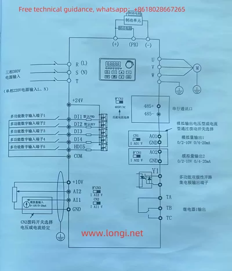
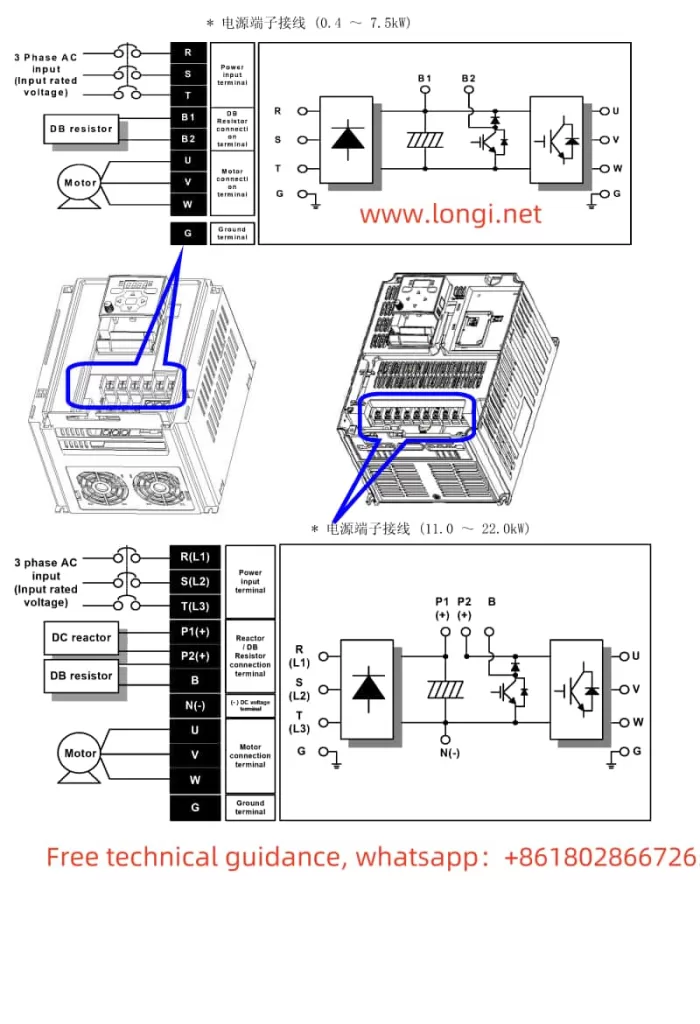
- Power Supply Wiring
- The power supply should be connected to a three-phase AC power source, typically with voltages of 380V or 660V. Ensure that the wiring is compatible with the rated power of the device and that the appropriate circuit protection (fuses, circuit breakers) is used.
- Verify that the power supply wiring is stable, and choose appropriately sized cables to avoid overheating or system malfunctions.
- Cooling System Piping
The induction heater is equipped with a water cooling system to regulate the temperature during operation. The cooling system includes an inlet and outlet pipe, both of which need to be connected securely.- Inlet: Connect to a clean water source with the required temperature and quality.
- Outlet: Ensure that water flows freely through the system and that the return pipe is not blocked.
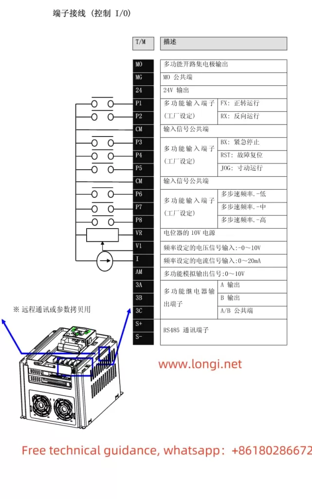
- Control System Wiring
The control system typically involves connecting the control panel, temperature sensors, and external control signals. Wiring should be done correctly to avoid electromagnetic interference and ensure accurate operation.- Ensure proper connections for the control panel and signal inputs.
- Minimize the risk of interference by avoiding running control cables parallel to high-voltage power cables.
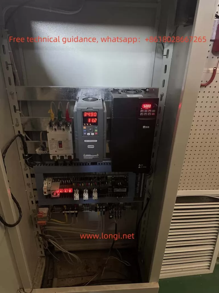
IV. Installation and Commissioning
- Installation Location
The induction heater should be installed in a dry, well-ventilated area with no corrosive gases or excessive humidity. The device should be placed on a stable surface to prevent vibrations from affecting performance. - Installation Steps
- First, confirm the correct wiring for the power supply, cooling system, and signal connections.
- Then, install the induction coil properly and ensure the distance between the coil and workpiece is suitable for efficient heating.
- Finally, connect the control system and perform initial tests.
- Commissioning and Operation
After installation, carry out the following steps:- Verify that the power supply, cooling system, and control panel are working correctly.
- Adjust the power, temperature, and overload protection parameters.
- Start the system, check the heating effect, cooling performance, and control panel response.
V. Daily Maintenance and Usage Precautions
- Maintenance
- Regularly check the cooling system to ensure proper water flow and water quality.
- Inspect power and control cables for wear or aging and replace them as needed.
- Clean the heater’s surface and heat dissipation components to maintain proper cooling efficiency.
- Usage Precautions
- Ensure that the heater is not placed near flammable materials to prevent fire hazards.
- Avoid overloading the device or making improper adjustments, which could cause damage.
- If the device is unused for extended periods, perform proper shutdown maintenance to maintain its condition.
Conclusion
The MC Huikai induction heater is a high-efficiency, energy-saving device widely used in various metal processing and heat treatment applications. This guide has provided a comprehensive introduction to the device’s technical parameters, wiring instructions, control settings, and daily usage precautions. By correctly installing, commissioning, and maintaining the heater, users can maximize its performance and ensure long-term reliability.