Posted on Leave a comment

Characteristics of ACS800 Drivers, abb acs800 troubleshooting manual

The ACS800 inverter, produced by ABB, is an advanced industrial frequency converter with several unique features that make it highly favored in the industrial control and drive sectors.
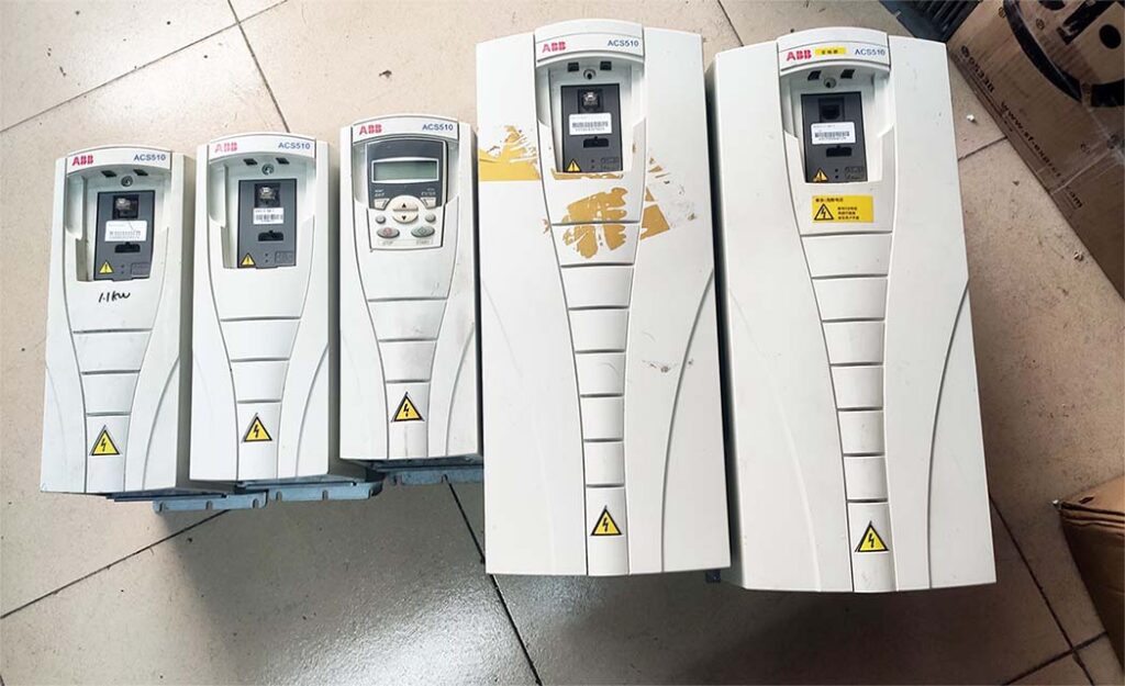
Firstly, the ACS800 inverter boasts a wide power range, from kilowatts to megawatts, suitable for various scales and complexities of industrial applications. This flexibility enables the ACS800 to meet the needs of different industries and applications, from small production lines to large factories.

Secondly, the ACS800 inverter exhibits outstanding performance and stability. It employs advanced control algorithms and technologies to achieve precise speed and torque control, ensuring stable and reliable equipment operation. Whether in harsh industrial environmental conditions or demanding production processes, the ACS800 performs exceptionally well.

Furthermore, the ACS800 inverter offers extensive features and options. It supports multiple communication interfaces for integration with various control systems, enabling flexible remote control and monitoring. Additionally, the ACS800 provides various protection functions, such as overload protection, short-circuit protection, and overvoltage protection, effectively safeguarding the safe operation of equipment and production systems.

The ACS800 inverter also emphasizes energy efficiency and environmental protection. By optimizing energy utilization and efficiency, the ACS800 can reduce energy consumption and production costs while minimizing environmental impact, in line with sustainable development requirements.

In conclusion, the ACS800 inverter, with its wide application range, excellent performance, rich features, and eco-friendly energy-saving characteristics, is an ideal choice for industrial control and drive applications. It not only improves production efficiency and quality but also reduces operating costs, creating greater value for users.Below is the ABB ACS800 troubleshooting manual.

Warning or Fault Message On The Panel Display Of ABB ACS800

An indication of an abnormal drive status appears as a warning or fault message on the panel display. You depend on the abb acs800 troubleshooting manual,Utilizing this information, most causes of warnings and faults can be identified and rectified. Should you encounter challenges beyond your expertise, do not hesitate to reach out to us for assistance.When you encounter a malfunction in the ABB ACS800 drive, you can also directly refer to this manual:

https://drive.google.com/file/d/1xIHyXqzHP-my4EsTVidbco33lgYWFXH5/view?usp=sharing

WARNING CAUSE WHAT TO DO
ACS800 TEMP (4210)
3.08 AW 1 bit 4
Drive IGBT temperature is excessive. Fault trip limit is 100%. Check ambient conditions. Check air flow and fan operation.
Check heatsink fins for dust pick-up. Check motor power against unit power.
AI < MIN FUNC (8110)
3.09 AW 2 bit 10
(programmable Fault Function 30.01)
Analogue control signal is below minimum allowed value due to incorrect signal level or failure in control wiring. Check for proper analogue control signal levels.
Check control wiring.
Check Fault Function parameters.
AD [message] Message generated by an EVENT block in the Adaptive Program. Consult the documentation or author of the Adaptive Program.
BACKUP USED (FFA3) PC stored backup of drive parameters is downloaded into use. Wait until download is completed.
BATT FAILURE (5581)
3.18 AW 5 bit 15
APBU branching unit memory backup battery error caused by
– incorrect APBU switch S3 setting
– too low battery voltage.
With parallel connected inverters, enable backup battery by setting actuator 6 of switch S3 to ON.
Replace backup battery.
BC OVERHEAT (7114)
3.18 AW 5 bit 3
Brake chopper overload Stop drive. Let chopper cool down.
Check parameter settings of resistor overload protection function (see parameter group 27 BRAKE CHOPPER).
Check that braking cycle meets allowed limits.
Check that drive supply AC voltage is not excessive.
BRAKE ACKN (FF74)
3.16 AW 4 bit 3
Unexpected state of brake acknowledge signal See parameter group 42 BRAKE CONTROL.
Check connection of brake acknowledgement signal.
BR OVERHEAT (7112)
3.18 AW 5 bit 2
Brake resistor overload Stop drive. Let resistor cool down.
Check parameter settings of resistor overload protection function (see parameter group 27 BRAKE CHOPPER).
Check that braking cycle meets allowed limits.
CALIBRA DONE (FF37) Calibration of output current transformers is completed. Continue normal operation.
CALIBRA REQ (FF36) Calibration of output current transformers is required. Displayed at start if drive is in scalar control (parameter 99.04) and scalar fly start feature is on (parameter 21.08). Calibration starts automatically. Wait for a while.
WARNING CAUSE WHAT TO DO
COMM MODULE (7510)
3.08 AW 1 bit 12
(programmable Fault Function 30.18, 30.19)
Cyclical communication between drive and master is lost. Check status of fieldbus communication. See chapter Fieldbus control, or appropriate fieldbus adapter manual.
Check parameter settings:
– group 51 COMM MODULE DATA (for fieldbus adapter)
– group 52 STANDARD MODBUS (for Standard Modbus Link).
Check Fault Function parameters. Check cable connections.
Check if master can communicate.
DC BUS LIM (3211)
3.18 AW5 bit 9
(programmable Fault Function 30.23)
Drive limits torque due to too high or too low intermediate circuit DC voltage. Informative alarm
Check Fault Function parameters.
EARTH FAULT (2330)
3.08 AW 1 bit 14
(programmable Fault Function 30.17)
Drive has detected load unbalance typically due to earth fault in motor or motor cable. Check there are no power factor correction capacitors or surge absorbers in motor cable.
Check that there is no earth fault in motor or motor cables:
– measure insulation resistances of motor and motor cable.
If no earth fault can be detected, contact your local ABB representative.
ENC CABLE (7310)
3.31 AW 6 bit 3
(programmable Fault Function 50.07)
Pulse encoder phase signal is missing. Check pulse encoder and its wiring.
Check pulse encoder interface module and its wiring.
ENCODER A<>B (7302)
3.09 AW 2 bit 4
Pulse encoder phasing is wrong: Phase A is connected to terminal of phase B and vice versa. Interchange connection of pulse encoder phases A and B.
ENCODER ERR (7301)
3.08 AW 1 bit 5
Communication fault between pulse encoder and pulse encoder interface module and between module and drive Check pulse encoder and its wiring, pulse encoder interface module and its wiring, parameter group 50 ENCODER MODULE settings.
FAN OTEMP (FF83)
3.16 AW 4 bit 0
Excessive temperature of drive output filter fan. Supervision is in use in step-up drives. Stop drive. Let it cool down. Check ambient temperature.
Check fan rotates in correct direction and air flows freely.
HW RECONF RQ (FF38) Inverter type (e.g. sr0025_3) has been changed. Inverter type is usually changed at factory or during drive implementation. Wait until alarm POWEROFF! activates and switch control board power off to validate inverter type change.
WARNING CAUSE WHAT TO DO
ID DONE (FF32) Drive has performed motor identification magnetisation and is ready for operation. This warning belongs to normal start-up procedure. Continue drive operation.
ID MAGN (FF31) Motor identification magnetisation is on. This warning belongs to normal start-up procedure. Wait until drive indicates that motor identification is completed.
ID MAGN REQ (FF30) Motor identification is required. This warning belongs to normal start-up procedure. Drive expects user to select how motor identification should be performed: By Identification Magnetisation or by ID Run. Start Identification Magnetisation by pressing Start key, or select ID Run and start (see parameter 99.10).
ID N CHANGED (FF68) Drive ID number has been changed from 1. Change ID number back to 1. See chapter
Control panel.
ID RUN (FF35) Motor identification Run is on. Wait until drive indicates that motor identification Run is completed.
ID RUN SEL (FF33) Motor Identification Run is selected, and drive is ready to start ID Run. This warning belongs to ID Run procedure. Press Start key to start Identification Run.
IN CHOKE TEMP (FF81)
3.18 AW 5 bit 4
Excessive input choke temperature Stop drive. Let it cool down. Check ambient temperature.
Check that fan rotates in correct direction and air flows freely.
INV CUR LIM (2212)
3.18 AW 5 bit 8
(programmable Fault Function 30.23)
Internal inverter current or power limit has been exceeded. Reduce load or increase ramp time.
Limit inverter actual power or decrease line- side converter reactive power generation reference value (parameter 95.06 LCU Q PW REF).
Check Fault Function parameters.
INV DISABLED (3200)
3.18 AW 5 bit 6
Optional DC switch has opened while unit was stopped. Close DC switch.
Check AFSC-0x Fuse Switch Controller unit.
WARNING CAUSE WHAT TO DO
INV OVERTEMP (4290)
3.31 AW 6 bit 0
Converter module temperature is excessive. Check ambient temperature. If it exceeds 40°C, ensure that load current does not exceed derated load capacity of drive. See appropriate hardware manual.
Check that ambient temperature setting is correct (parameter 95.10).
Check converter module cooling air flow and fan operation.
Cabinet installation: Check cabinet air inlet filters. Change when necessary. See appropriate hardware manual.
Modules installed in cabinet by user: Check that cooling air circulation in cabinet has been prevented with air baffles. See module installation instructions.
Check inside of cabinet and heatsink of converter module for dust pick-up. Clean when necessary.
IO CONFIG (FF8B)
(programmable Fault Function 30.22)
Input or output of optional I/O extension or fieldbus module has been selected as signal interface in application program but communication to appropriate I/O extension module has not been set accordingly. Check Fault Function parameters.
Check parameter group 98 OPTION MODULES.
MACRO CHANGE (FF69) Macro is restoring or User macro is being saved. Wait until drive has finished task.
MOD BOARD T (FF88)
09.11 AW 3 bit 14
Overtemperature in AINT board of inverter module. Check inverter fan.
Check ambient temperature.
MOD CHOKE T (FF89)
09.11 AW 3 bit 13
Overtemperature in choke of liquid cooled R8i inverter module. Check inverter fan.
Check ambient temperature. Check liquid cooling system.
MOT CUR LIM (2300)
3.18 AW 5 bit 10
(programmable Fault Function 30.23)
Drive limits motor current according to current limit defined by parameter 20.03 MAXIMUM CURRENT. Reduce load or increase ramp time.
Increase parameter 20.03 MAXIMUM CURRENT value.
Check Fault Function parameters.
MOTOR STALL (7121)
3.09 AW 2 bit 9
(programmable Fault Function 30.10)
Motor is operating in stall region due to e.g. excessive load or insufficient motor power. Check motor load and drive ratings. Check Fault Function parameters.
MOTOR STARTS (FF34) Motor Identification Run starts. This warning belongs to ID Run procedure. Wait until drive indicates that motor identification is completed.
WARNING CAUSE WHAT TO DO
MOTOR TEMP (4310)
3.08 AW 1 bit 3
(programmable Fault Function 30.04…30.09)
Motor temperature is too high (or appears to be too high) due to excessive load, insufficient motor power, inadequate cooling or incorrect start-up data. Check motor ratings, load and cooling. Check start-up data.
Check Fault Function parameters.
MOTOR 1 TEMP
(4312)
3.16 AW 4 bit 1
Measured motor temperature has exceeded alarm limit set by parameter 35.02. Check value of alarm limit.
Check that actual number of sensors corresponds to value set by parameter.
Let motor cool down. Ensure proper motor cooling: Check cooling fan, clean cooling surfaces, etc.
MOTOR 2 TEMP
(4313)
3.16 AW 4 bit 2
Measured motor temperature has exceeded alarm limit set by parameter 35.05. Check value of alarm limit.
Check that actual number of sensors corresponds to value set by parameter.
Let motor cool down. Ensure proper motor cooling: Check cooling fan, clean cooling surfaces, etc.
MOT POW LIM (FF86)
3.18 AW 5 bit 12
(programmable Fault Function 30.23)
Drive limits motor power according to limits defined by parameters 20.11 and 20.12. Informative alarm
Check parameter 20.11 P MOTORING LIM and 20.12 P GENERATING LIM settings.
Check Fault Function parameters.
MOT TORQ LIM (FF85)
3.18 AW 5 bit 11
(programmable Fault Function 30.23)
Drive limits motor torque according to calculated motor pull-out torque limit and minimum and maximum torque limits defined by parameters 20.13 and 20.14. Informative alarm
Check parameter 20.13 MIN TORQ SEL and
20.14 MAX TORQ SEL settings. Check Fault Function parameters.
If LIMIT WORD 1 bit 0 TORQ MOTOR LIM
is 1,
– check motor parameter settings (parameter group 99 START-UP DATA)
– ensure that ID run has been completed successfully.
PANEL LOSS (5300)
3.09 AW 2 bit 13
(programmable Fault Function 30.02)
Control panel selected as active control location for drive has ceased communicating. Check panel connection (see appropriate hardware manual).
Check control panel connector.
Replace control panel in mounting platform. Check Fault Function parameters.
POINTER ERROR (FFD0) Source selection (pointer) parameter points to non existing parameter index. Check source selection (pointer) parameter settings.
->POWEROFF! (FF39) Inverter type (e.g. sr0025_3) has been changed. Inverter type is usually changed at factory or during drive implementation. Switch control board power off to validate inverter type change.
WARNING CAUSE WHAT TO DO
PPCC LINK (5210)
3.06 FW 2 bit 11
Fibre optic link to INT board is faulty. Check fibre optic cables or galvanic link. With frame sizes R2-R6 link is galvanic.
If RMIO is powered from external supply, ensure that supply is on. See parameter 16.09 CTRL BOARD SUPPLY.
Check signal 03.19. Contact ABB representative if any of faults in signal 3.19 are active.
PPCC LINK xx INT board fibre optic connection fault in inverter unit of several parallel connected inverter modules. xx refers to inverter module number. Check connection from inverter module Main Circuit Interface Board, INT to PPCC Branching Unit, PBU. (Inverter module 1 is connected to PBU INT1 etc.)
Check signal 03.19. Contact ABB representative if any of faults in signal 3.19 are active.
(5210)
3.06 FW 2 bit 11 and
4.01
PP OVERLOAD (5482)
3.18 AW 5 bit 5
Excessive IGBT junction to case temperature. This can be caused by excessive load at low frequencies (e.g. fast direction change with excessive load and inertia). Increase ramp time. Reduce load.
REPLACE FAN (4280)
3.18 AW 5 bit 0
Running time of inverter cooling fan has exceeded its estimated life time. Replace fan.
Reset fan run time counter 01.44.
RUN ENABLE (FF8E)
3.06 FW 2 bit 4
No Run enable signal received. Check setting of parameter 16.01. Switch on signal or check wiring of selected source.
SLEEP MODE (FF8C)
3.16 AW 4 bit 4
Sleep function has entered sleeping mode. See parameter group 40 PID CONTROL.
START INHIBI (FF7A)
AW 1 bit 0
Safe torque off function has been activated while drive was stopped.
Or: Optional start inhibit hardware logic is activated.
Close Safe torque off function switch. If switch is closed and warning is still active, check power supply at ASTO board input terminals. Replace ASTO board.
Or: Check start inhibit circuit (AGPS board).
START INTERL (FF8D) No Start Interlock signal received. Check circuit connected to Start Interlock input on RMIO board.
SYNCRO SPEED (FF87)
3.18 AW 5 bit 1
Value of motor nominal speed set to parameter
99.08 is not correct: Value is too near synchronous speed of motor. Tolerance is 0.1%. This warning is active only in DTC mode.
Check nominal speed from motor rating plate and set parameter 99.08 exactly accordingly.
WARNING CAUSE WHAT TO DO
TEMP DIF xx y (4380)
4.01 FAULTED INT INFO
Excessive temperature difference between several parallel connected inverter modules. xx (1…12) refers to inverter module number and y refers to phase (U, V, W). Check cooling fan. Replace fan.
Check air filters.
Alarm is indicated when temperature difference is 15°C. Fault is indicated when temperature difference is 20°C.
Excessive temperature can be caused e.g. by unequal current sharing between parallel connected inverters.
THERMISTOR (4311) Motor temperature is excessive. Motor thermal protection mode selection is TEMP SENSOR. Check motor ratings and load. Check start-up data.
3.08 AW 1 bit 2
(programmable Fault Function 30.04…30.05)
Check thermistor connections to digital input DI6.
T MEAS ALM (FF91)
3.08 AW 1 bit 6
Motor temperature measurement is out of acceptable range. Check connections of motor temperature measurement circuit. See chapter Program features for circuit diagram.
UNDERLOAD (FF6A) Motor load is too low due to e.g. release mechanism in driven equipment. Check for problem in driven equipment. Check Fault Function parameters.
3.09 AW 2 bit 1
(programmable Fault Function 30.13)
USER L CURVE (2312)
3.18 AW 5 bit 13
Integrated motor current has exceeded load curve defined by parameters in group 72 USER LOAD CURVE. Check parameter group 72 USER LOAD CURVE settings.
Reduce load.
WARNING CAUSE WHAT TO DO
DOWNLOADING FAILED Download function of panel has failed. No data has been copied from panel to drive. Make sure panel is in local mode.
Retry (there might be interference on link). Contact ABB representative.
DRIVE IS RUNNING DOWNLOADING NOT POSSIBLE Downloading is not possible while motor is running. Stop motor. Perform downloading.
NO COMMUNICATION (X) Cabling problem or hardware malfunction on Panel Link Check Panel Link connections.
Press RESET key. Panel reset may take up to half a minute, please wait.
(4) = Panel type not compatible with drive application program version Check panel type and drive application program version. Panel type is printed on panel cover. Application program version is stored in parameter 33.02.
NO FREE ID NUMBERS ID NUMBER SETTING NOT POSSIBLE Panel Link already includes 31 stations. Disconnect another station from link to free ID number.
NOT UPLOADED DOWNLOADING NOT POSSIBLE No upload function has been performed. Perform upload function before downloading. See chapter Control panel.
UPLOADING FAILED Upload function of panel has failed. No data has been copied from drive to panel. Retry (there might be interference on link). Contact ABB representative.
WRITE ACCESS DENIED PARAMETER SETTING NOT POSSIBLE Certain parameters do not allow changes while motor is running. If tried, no change is accepted, and warning is displayed.
Parameter lock is on.
Stop motor, then change parameter value.
Open parameter lock (see parameter 16.02).
FAULT CAUSE WHAT TO DO
ACS800 TEMP (4210)
3.05 FW 1 bit 3
Drive IGBT temperature is excessive. Fault trip limit is 100%. Check ambient conditions. Check air flow and fan operation.
Check heatsink fins for dust pick-up. Check motor power against unit power.
ACS TEMP xx y (4210)
3.05 FW 1 bit 3 and 4.01
Excessive internal temperature in inverter unit of several parallel connected inverter modules. xx (1…12) refers to inverter module number and y refers to phase (U, V, W). Check ambient conditions. Check air flow and fan operation.
Check heatsink fins for dust pick-up. Check motor power against unit power.
AI < MIN FUNC (8110)
3.06 FW 2 bit 10
(programmable Fault Function 30.01)
Analogue control signal is below minimum allowed value due to incorrect signal level or failure in control wiring. Check for proper analogue control signal levels.
Check control wiring.
Check Fault Function parameters.
AD [message] Message generated by an EVENT block in the Adaptive Program. Consult the documentation or author of the Adaptive Program.
BACKUP ERROR (FFA2) Failure when restoring PC stored backup of drive parameters. Retry.
Check connections.
Check that parameters are compatible with drive.
BC OVERHEAT (7114)
3.17 FW 5 bit 4
Brake chopper overload Let chopper cool down.
Check parameter settings of resistor overload protection function (see parameter group 27 BRAKE CHOPPER).
Check that braking cycle meets allowed limits.
Check that drive supply AC voltage is not excessive.
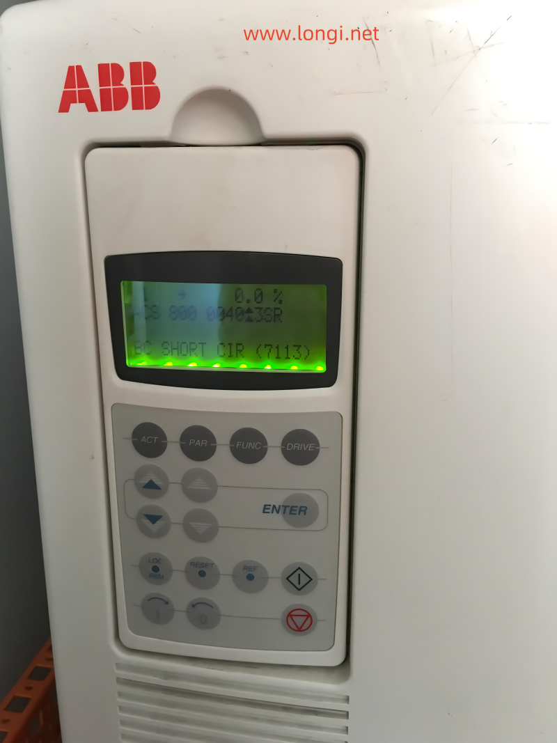
BC SHORT CIR (7113)
3.17 FW 5 bit 2
Short circuit in brake chopper IGBT(s) Replace brake chopper.
Ensure brake resistor is connected and not damaged.
BRAKE ACKN (FF74)
3.15 FW 4 bit 3
Unexpected state of brake acknowledge signal See parameter group 42 BRAKE CONTROL.
Check connection of brake acknowledgement signal.
BR BROKEN (7110)
3.17 FW 5 bit 0
Brake resistor is not connected or it is damaged.
Resistance rating of brake resistor is too high.
Check resistor and resistor connection.
Check that resistance rating meets specifications. See appropriate drive hardware manual.
FAULT CAUSE WHAT TO DO
BR OVERHEAT (7112)
3.17 FW 5 bit 3
Brake resistor overload Let resistor cool down.
Check parameter settings of resistor overload protection function (see parameter group 27 BRAKE CHOPPER).
Check that braking cycle meets allowed limits.
Check that drive supply AC voltage is not excessive.
BR WIRING (7111)
3.17 FW 5 bit 1
Wrong connection of brake resistor Check resistor connection.
Ensure brake resistor is not damaged.
CHOKE OTEMP (FF82) Excessive temperature of drive output filter. Supervision is in use in step-up drives. Let drive cool down.
Check ambient temperature.
Check filter fan rotates in correct direction and air flows freely.
COMM MODULE (7510)
3.06 FW 2 bit 12
Cyclical communication between drive and master is lost. Check status of fieldbus communication. See chapter Fieldbus control, or appropriate fieldbus adapter manual.
(programmable Fault Function 30.18, 30.19) Check parameter settings:
– group 51 COMM MODULE DATA (for fieldbus adapter), or
– group 52 STANDARD MODBUS (for Standard Modbus Link).
Check Fault Function parameters.
Check cable connections.
Check if master can communicate.
CTRL B TEMP (4110)
3.06 FW 2 bit 7
Control board temperature is above 88°C. Check ambient conditions. Check air flow.
Check main and additional cooling fans.
CURR MEAS (2211) Current transformer failure in output current measurement circuit Check current transformer connections to Main Circuit Interface Board, INT.
CUR UNBAL xx (2330) Drive has detected excessive output current unbalance in inverter unit of several parallel connected inverter modules. This can be caused by external fault (earth fault, motor, motor cabling, etc.) or internal fault (damaged inverter component). xx (1…12) refers to inverter module number. Check there are no power factor correction capacitors or surge absorbers in motor cable.
3.05 FW 1 bit 4 and 4.01 Check that there is no earth fault in motor or motor cables:
(programmable Fault Function 30.17) – measure insulation resistances of motor and motor cable.
If no earth fault can be detected, contact your local ABB representative.
DC HIGH RUSH (FF80) Drive supply voltage is excessive. When supply voltage is over 124% of unit voltage rating (415, 500 or 690 V), motor speed rushes to trip level (40% of nominal speed). Check supply voltage level, drive rated voltage and allowed voltage range of drive.
FAULT CAUSE WHAT TO DO
DC OVERVOLT (3210)
3.05 FW 1 bit 2
Excessive intermediate circuit DC voltage.
DC overvoltage trip limit is 1.3 × 1.35 × U1max, where U1max is maximum value of supply voltage range. For 400 V units, U1max is 415 V. For 500 V units, U1max is 500 V. For 690 V units, U1max is 690 V. Actual voltage in intermediate circuit corresponding to the
supply voltage trip level is 728 V DC for 400 V units, 877 V DC for 500 V units, and
1210 V DC for 690 V units.
Check that overvoltage controller is on (parameter 20.05).
Check supply voltage for static or transient overvoltage.
Check brake chopper and resistor (if used). Check deceleration time.
Use coast-to-stop function (if applicable).
Retrofit frequency converter with brake chopper and brake resistor.
DC UNDERVOLT (3220)
3.06 FW 2 bit 2
Intermediate circuit DC voltage is not sufficient due to missing supply voltage phase, blown fuse or rectifier bridge internal fault.
DC undervoltage trip limit is 0.6 × 1.35 × U1min, where U1min is minimum value of supply voltage range. For 400 V and 500 V units,
U1min is 380 V. For 690 V units, U1min is 525 V. Actual voltage in intermediate circuit corresponding to supply voltage trip level is
307 V DC for 400 V and 500 V units, and 425 V DC for 690 V units.
Check main supply and fuses.
EARTH FAULT (2330)
3.05 FW 1 bit 4
(programmable Fault Function 30.17)
Drive has detected load unbalance typically due to earth fault in motor or motor cable. Check there are no power factor correction capacitors or surge absorbers in motor cable.
Check that there is no earth fault in motor or motor cables:
– measure insulation resistances of motor and motor cable.
If no earth fault can be detected, contact your local ABB representative.
ENC CABLE (7310)
3.33 FW 6 bit 2
(programmable Fault Function 50.07)
Pulse encoder phase signal is missing. Check pulse encoder and its wiring.
Check pulse encoder interface module and its wiring.
ENCODER A<>B (7302) Pulse encoder phasing is wrong: Phase A is connected to terminal of phase B and vice versa. Interchange connection of pulse encoder phases A and B.
ENCODER ERR (7301)
3.06 FW 2 bit 5
Communication fault between pulse encoder and pulse encoder interface module and between module and drive Check pulse encoder and its wiring, pulse encoder interface module and its wiring and parameter group 50 ENCODER MODULE settings.
EXTERNAL FLT (9000)
3.06 FW 2 bit 8
(programmable Fault Function 30.03)
Fault in external device. (This information is configured through one of programmable digital inputs.) Check external devices for faults.
Check parameter 30.03 EXTERNAL FAULT.
FAULT CAUSE WHAT TO DO
FORCED TRIP (FF8F) Generic Drive Communication Profile trip command See appropriate communication module manual.
GD DISABLED (FF53) AGPS power supply of parallel connected R8i inverter module has been switched off during run. X (1…12) refers to inverter module number. Check Prevention of Unexpected Start-up circuit.
Replace AGPS board of R8i inverter module.
ID RUN FAIL (FF84) Motor ID Run is not completed successfully. Check maximum speed (parameter 20.02). It should be at least 80% of motor nominal speed (parameter 99.08).
IN CHOKE TEMP (FF81)
3.17 FW 5 bit 5
Excessive input choke temperature Stop drive. Let it cool down. Check ambient temperature.
Check that fan rotates in correct direction and air flows freely.
INT CONFIG (5410)
03.17 FW 5 bit 10
Number of inverter modules is not equal to original number of inverters. Check status of inverters. See signal 04.01 FAULTED INT INFO.
Check fibre optic cables between APBU and inverter modules.
If Reduced Run function is used, remove faulted inverter module from main circuit and write number of remaining inverter modules into parameter 95.03 INT CONFIG USER. Reset drive.
INV DISABLED
03.17 FW 5 bit 7
(3200)
Optional DC switch has opened while unit was running or start command was given. Close DC switch.
Check AFSC-0x Fuse Switch Controller unit.
INV OVERTEMP (4290)
3.17 FW 5 bit 13
Converter module temperature is excessive. Check ambient temperature. If it exceeds 40°C, ensure that load current does not exceed derated load capacity of drive. See appropriate hardware manual.
Check that ambient temperature setting is correct (parameter 95.10).
Check converter module cooling air flow and fan operation.
Cabinet installation: Check cabinet air inlet filters. Change when necessary. See appropriate hardware manual.
Modules installed in cabinet by user: Check that cooling air circulation in cabinet has been prevented with air baffles. See module installation instructions.
Check inside of cabinet and heatsink of converter module for dust pick-up. Clean when necessary.
Reset and restart after problem is solved and let converter module cool down.
FAULT CAUSE WHAT TO DO
I/O COMM ERR (7000)
3.06 FW 2 bit 6
Communication error on control board, channel CH1
Electromagnetic interference
Check connections of fibre optic cables on channel CH1.
Check all I/O modules (if present) connected to channel CH1.
Check for proper earthing of equipment. Check for highly emissive components nearby.
LINE CONV (FF51) Fault on line side converter Shift panel from motor side converter control board to line side converter control board.
See line side converter manual for fault description.
MOD BOARD T (FF88) Overtemperature in AINT board of inverter module. Check inverter fan.
Check ambient temperature.
MOD CHOKE T (FF89) Overtemperature in choke of liquid cooled R8i inverter module. Check inverter fan.
Check ambient temperature. Check liquid cooling system.
MOTOR PHASE (FF56)
3.06 FW 2 bit 15
(programmable Fault Function 30.16)
One of motor phases is lost due to fault in motor, motor cable, thermal relay (if used) or internal fault. Check motor and motor cable. Check thermal relay (if used).
Check Fault Function parameters. Disable this protection.
MOTOR STALL (7121)
3.06 FW 2 bit 14
(programmable Fault Function 30.10…30.12)
Motor is operating in stall region due to e.g. excessive load or insufficient motor power. Check motor load and drive ratings. Check Fault Function parameters.
MOTOR TEMP (4310)
3.05 FW 1 bit 6
(programmable Fault Function 30.04…30.09)
Motor temperature is too high (or appears to be too high) due to excessive load, insufficient motor power, inadequate cooling or incorrect start-up data. Check motor ratings and load. Check start-up data.
Check Fault Function parameters.
MOTOR 1 TEMP
(4312)
3.15 FW 4 bit 1
Measured motor temperature has exceeded fault limit set by parameter 35.03. Check value of fault limit.
Let motor cool down. Ensure proper motor cooling: Check cooling fan, clean cooling surfaces, etc.
MOTOR 2 TEMP
(4313)
3.15 FW 4 bit 2
Measured motor temperature has exceeded fault limit set by parameter 35.06. Check value of fault limit.
Let motor cool down. Ensure proper motor cooling: Check cooling fan, clean cooling surfaces, etc.
NO MOT DATA (FF52)
3.06 FW 2 bit 1
Motor data is not given or motor data does not match with inverter data. Check motor data parameters 99.04…99.09.
FAULT CAUSE WHAT TO DO
POWERF INV xx (3381)
3.17 FW 5 bit 9 and
INT board powerfail in inverter unit of several parallel connected inverter modules. xx (1…12) refers to inverter module number. Check that INT board power cable is connected.
Check that POW board is working correctly.
4.01 Replace INT board.
PPCC LINK (5210)
3.06 FW 2 bit 11
Fibre optic link to INT board is faulty. Check fibre optic cables or galvanic link. With frame sizes R2-R6 link is galvanic.
If RMIO is powered from external supply, ensure that supply is on. See parameter 16.09 CTRL BOARD SUPPLY.
Check signal 03.19. Contact ABB representative if any of faults in signal 3.19 are active.
PPCC LINK xx INT board fibre optic connection fault in inverter unit of several parallel connected inverter modules. xx refers to inverter module number. Check connection from inverter module Main Circuit Interface Board, INT to PPCC Branching Unit, PBU. (Inverter module 1 is connected to PBU INT1 etc.)
Check signal 03.19. Contact ABB representative if any of faults in signal 3.19 are active.
(5210)
3.06 FW 2 bit 11 and
4.01
PP OVERLOAD (5482)
3.17 FW 5 bit 6
Excessive IGBT junction to case temperature. This fault protects IGBT(s) and it can be activated by short circuit at output of long motor cables. Check motor cables.
SC INV xx y Short circuit in inverter unit of several parallel Check motor and motor cable.
(2340)
3.05 FW 1 bit 0, 4.01
connected inverter modules. xx (1…12) refers to inverter module number and y refers to
phase (U, V, W).
Check power semiconductors (IGBTs) of inverter module.
and 4.02
SHORT CIRC Short-circuit in motor cable(s) or motor Check motor and motor cable.
(2340) Check there are no power factor correction
3.05 FW 1 bit 0 and capacitors or surge absorbers in motor cable.
4.02
Output bridge of converter unit is faulty. Contact ABB representative.
SLOT OVERLAP (FF8A) Two option modules have same connection interface selection. Check connection interface selections in group 98 OPTION MODULES.
START INHIBI (FF7A)
3.03 bit 8
Safe torque off has been activated during motor run or motor start command has been given when Safe torque off is active.
Or: Optional start inhibit hardware logic is activated.
Close Safe torque off switch. If switch is closed and fault is still active, check power supply at ASTO board input terminals. Replace ASTO board.
Or: Check start inhibit circuit (AGPS board).
SUPPLY PHASE (3130)
3.06 FW 2 bit 0
Intermediate circuit DC voltage is oscillating due to missing supply voltage phase, blown fuse or rectifier bridge internal fault.
Trip occurs when DC voltage ripple is 13% of DC voltage.
Check main supply fuses.
Check for main supply imbalance.
FAULT CAUSE WHAT TO DO
TEMP DIF xx y (4380)
3.17 FW 5 bit 8 and 4.01
Excessive temperature difference between several parallel connected inverter modules. xx (1…12) refers to inverter module number and y refers to phase (U, V, W). Check cooling fan. Replace fan.
Check air filters.
Alarm is indicated when temperature difference is 15°C. Fault is indicated when temperature difference is 20°C
Excessive temperature can be caused e.g. by unequal current sharing between parallel connected inverters.
THERMAL MODE (FF50) Motor thermal protection mode is set to DTC for high-power motor. See parameter 30.05.
THERMISTOR (4311) Motor temperature is excessive. Motor thermal protection mode selection is TEMP SENSOR. Check motor ratings and load. Check start-up data.
3.05 FW 1 bit 5
(programmable Fault Function 30.04…30.05)
Check thermistor connections to digital input DI6.
UNDERLOAD (FF6A) Motor load is too low due to e.g. release mechanism in driven equipment. Check for problem in driven equipment. Check Fault Function parameters.
3.05 FW 1 bit 8
(programmable Fault Function 30.13…30.15)
USER L CURVE (2312)
3.17 FW 5 bit 11
Integrated motor current has exceeded load curve defined by parameter group 72 USER LOAD CURVE. Check parameter group 72 USER LOAD CURVE settings.
After motor cooling time specified by parameter 72.20 LOAD COOLING TIME has elapsed, fault can be reset.
USER MACRO (FFA1)
3.07 SFW bit 1
No User Macro saved or file is defective. Create User Macro.

When encountering issues with your ACS800 inverter, it’s essential to follow proper troubleshooting procedures to address the problem effectively. Referencing the “ABB ACS800 troubleshooting manual” can provide invaluable guidance in diagnosing and resolving faults. Here are steps to handle ACS800 inverter faults:

  1. Identify the Fault Code: Upon encountering a fault, the ACS800 inverter typically displays a fault code on the panel display. Refer to the “ABB ACS800 troubleshooting manual” to interpret the specific fault code and understand its implications.
  2. Consult the Troubleshooting Manual: Once you’ve identified the fault code, consult the “ABB ACS800 troubleshooting manual” for detailed instructions on diagnosing and addressing the issue. The manual provides comprehensive troubleshooting procedures tailored to the ACS800 inverter’s specific components and functionalities.
  3. Follow Troubleshooting Steps: Follow the step-by-step troubleshooting steps outlined in the manual to systematically diagnose the fault. The manual offers insights into potential causes of the fault, along with recommended actions to resolve the issue promptly.
  4. Refer to Technical Support: In cases where troubleshooting efforts are unsuccessful or additional assistance is required, don’t hesitate to contact technical support. The “ABB ACS800 troubleshooting manual” serves as a valuable resource for technicians and support personnel, enabling them to provide informed assistance based on the specific fault encountered.
  5. Document and Learn: Throughout the troubleshooting process, document your observations, actions taken, and outcomes. This documentation can serve as a reference for future troubleshooting endeavors and contribute to continuous learning and improvement in managing ACS800 inverter faults.

By adhering to the guidance provided in the “ABB ACS800 troubleshooting manual” and following established troubleshooting procedures, you can effectively address faults encountered with your ACS800 inverter, minimizing downtime and ensuring optimal performance.

Posted on Leave a comment

The characteristics of ACS355 inverter,abb acs355 fault codes list,acs355 manual fault

Introduction to the Features of ABB VFD ACS355 Series

The ABB VFD ACS355 series represents a significant advancement in variable frequency drive technology, offering a range of features that are tailored for optimal performance and ease of use. Here are some key characteristics of this series:

  1. Compact and Efficient Design: The ACS355 series is designed for space-saving installation, making it ideal for applications where space is at a premium. Despite its compact size, it packs a punch in terms of performance, delivering efficient motor control for a wide range of industrial applications.
  2. User-Friendly Interface: The series boasts an intuitive control panel with a clear display, allowing for easy navigation and setup. This user-friendly interface reduces the learning curve for operators, enhancing productivity and minimizing downtime.
  3. Advanced Motor Control: The ACS355 series incorporates advanced motor control algorithms that ensure precise speed and torque control. This ensures optimal performance of the connected motor, resulting in improved process efficiency and reduced energy consumption.
  4. Robust and Reliable: Designed for harsh industrial environments, the ACS355 series features a robust construction that can withstand dust, moisture, and temperature fluctuations. This ensures reliable operation and extended service life, even in demanding conditions.
  5. Flexible Connectivity: The series offers a range of connectivity options, including built-in Ethernet and fieldbus interfaces, enabling easy integration into existing automation systems. This flexibility simplifies system design and reduces installation costs.
  6. Comprehensive Protection Features: The ACS355 series incorporates a range of protective features, such as overcurrent, overvoltage, and thermal protection, to safeguard the drive and connected motor against potential damage. This enhances system reliability and reduces maintenance requirements.

In summary, the ABB VFD ACS355 series offers a compelling combination of compact design, user-friendliness, advanced motor control, robustness, flexible connectivity, and comprehensive protection features. These characteristics make it an ideal choice for a wide range of industrial applications where reliable and efficient motor control is essential.

LED status description and alarm meaning

Where LED   off LED   lit and steady LED   blinking
On the front of
     the drive.
     If a control panel
     is attached to the
     drive, switch to
     remote control
     (otherwise a fault
     will be
     generated), and
     then remove the
     panel to be able
     to see the LEDs
No power Green Power supply on
     the board OK
Green Drive in an   alarm
     state
Red Drive in a   fault
     state. To reset
     the fault, press
     RESET from the
     control panel or
     switch off the
     drive power
Red Drive in a   fault state.
     To reset the fault,
     switch off the drive
     power
At the top left
     corner of the
     assistant control panel
Panel has no
     power or no
     drive
     connection.
Green Drive in a   normal
     state
Green Drive in an alarm
     state
Red Drive in a   fault
     state. To reset
     the fault, press
     RESET from the
     control panel or
     switch off the
     drive power
Red  


ABB Drives ACS355 Fault Codes List mamual,”Fault” means that the drive has experienced a serious malfunction, usually a hardware issue that needs to be removed for repair.

CODE FAULT CAUSE WHAT TO DO
1 OVERCURRENT (2310)
     0305 bit 0
Output current has exceeded trip level.  
Sudden load change or stall. Check motor load and mechanics.
Insufficient acceleration   time. Check acceleration time (2202 and 2205).   Check the possibility of using vector control.
Incorrect motor data. Check that motor data (Group 99) is equal to motor rating plate   values. If using vector control, perform ID run (9910).
Motor and/or drive is too   small for the application. Check sizing.
Damaged motor cables,   damaged motor or wrong motor connection (star/delta). Check motor, motor cable and connections (including phasing).
Internal fault of the drive.   Drive gives an overcurrent fault after start command even when the motor is   not connected (use scalar control in this trial). Replace the drive.
High frequency noise in STO   lines. Check the STO cabling and remove the noise sources nearby.
2 DC OVERVOLT (3210)
     0305 bit 1
Excessive intermediate circuit DC voltage. DC overvoltage trip   limit is 420 V for 200 V drives
     and 840 V for 400 V drives.
 
Supply voltage is too high   or noisy. Static or transient overvoltage in the input power supply. Check input voltage level and check power line for static or   transient overvoltage
If the drive is used in a   floating network, DC overvoltage fault may appear In a floating network, remove the EMC screw from the drive.
CODE FAULT CAUSE WHAT TO DO
If the overvoltage fault appears during deceleration, possible causes are:
• Overvoltage controller disabled.
• Deceleration time is too short.
• Faulty or undersized braking chopper.
• Check that overvoltage controller is on (parameter 2005 OVERVOLT CTRL).
• Check deceleration time (2203,
2206).
• Check brake chopper and resistor (if used). DC overvoltage control must be deactivated when brake chopper and resistor is used (parameter 2005 OVERVOLT CTRL). Retrofit drive with brake chopper and brake resistor.
0003 DEV OVERTEMP (4210)
0305 bit 2
Drive IGBT temperature is excessive. The fault trip limit depends on the drive type and size.
Ambient temperature is too high. Check ambient conditions. See also section Derating on page 378.
Airflow through the inverter is not free. Check air flow and free space above and below the drive (see section Free space around the drive on page 34).
Fan is not working properly Check fan operation.
Overloading of the drive. 50% overload is allowed for one minute in ten minutes. If higher switching frequency (parameter 2606) is used, follow the Derating rules on page 378.
0004 SHORT CIRC (2340)
0305 bit 3
Short-circuit in motor cable(s) or motor.
Damaged motor or motor cable. Check motor and cable insulation. Check motor winding
Internal fault of the drive. Drive gives an overcurrent fault after start command even when the motor is not connected (use scalar control in this trial). Replace the drive.
High frequency noise in STO lines. Check the STO cabling and remove the noise sources nearby.
0006 DC UNDERVOLT (3220)
0305 bit 5
Intermediate circuit DC voltage is not sufficient. Check input power supply and fuses.
Undervoltage controller disabled. Check that undervoltage controller is on (parameter 2006 UNDERVOLT CTRL).
CODE FAULT CAUSE WHAT TO DO
Missing input power line phase. Measure the input and DC voltage during start, stop and running by using a multimeter or check parameter 0107 DC BUS VOLTAGE.
Blown fuse Check the condition of input fuses.
Rectifier bridge internal fault. Replace the drive.
0007 AI1 LOSS (8110)
0305 bit 6
Analog input AI1 signal has fallen below limit defined by parameter
3021 AI1 FAULT LIMIT.
(programmable fault function 3001, 3021)
Analog input signal is weak or does not exist. Check the source and wire connections of the analog input.
Analog input signal is lower than fault limit. Check parameters 3001 AI<MIN FUNCTION and 3021 AI1 FAULT LIMIT.
0008 AI2 LOSS (8110)
0305 bit 7
Analog input AI2 signal has fallen below limit defined by parameter
3022 AI2 FAULT LIMIT.
.
(programmable fault function
3001, 3022)
Analog input signal is weak or does not exist. Check the source and wire connections of analog input.
Analog input signal is lower than fault limit. Check parameters 3001 AI<MIN FUNCTION and 3021 AI1 FAULT LIMIT.
CODE FAULT CAUSE WHAT TO DO
0009 MOT OVERTEMP (4310)
0305 bit 8
(programmable fault function 3005…3009 3504)
Motor temperature estimation is too high.
Excessive load or insufficient motor power Check motor ratings, load and cooling.
Incorrect start-up data. Check start-up data.
Check fault function parameters
3005…3009.
Minimize IR compensation to avoid heating (parameter 2603 IR COMP VOLT).
Check frequency of the motor (low running frequency of motor with high input current can cause this fault).
Let the motor cool down. The necessary cooling time period depends on the value of parameter 3006 MOT THERM TIME. Motor
temperature estimation is counted down only when the drive is powered on.
Measured motor temperature has exceeded the fault limit set by parameter 3504 FAULT LIMIT. Check value of fault limit.
Check that actual number of sensors corresponds to value set by parameter 3501 SENSOR TYPE.
Let the motor cool down. Ensure proper motor cooling: Check the cooling fan, clean cooling surfaces, etc.
0010 PANEL LOSS (5300)
0305 bit 9
(programmable fault function 3002)
Control panel selected as active control location for drive has ceased communicating. Check panel connection.
Check fault function parameters.
Check parameter 3002 PANEL COMM ERR.
Check control panel connector.
Refit control panel in mounting platform.
If the drive is in external control mode (REM) and is set to accept start/stop, direction commands or references through control panel:
Check group 10 START/STOP/DIR
and 11 REFERENCE SELECT
settings.
0011 ID RUN FAIL (FF84)
0305 bit 10
Motor ID run is not completed successfully. Check motor connection.
Check start-up data (group 99 START- UP DATA).
Check maximum speed (parameter 2002). It should be at least 80% of motor nominal speed (parameter 9908).
Ensure ID run has been performed according to instructions in section ID run procedure on page 71.
CODE FAULT CAUSE WHAT TO DO
0012 MOTOR STALL (7121)
0305 bit 11
(programmable fault function 3010…3012)
Motor is operating in stall region due to, eg, excessive load or insufficient motor power. Check motor load and drive ratings.
Check fault function parameters
3010…3012.
0014 EXT FAULT 1
(9000)
0305 bit 13
(programmable fault function 3003)
External fault 1 Check external devices for faults.
Check parameter 3003 EXTERNAL FAULT 1 setting.
0015 EXT FAULT 2
(9001)
0305 bit 14
(programmable fault function 3004)
External fault 2 Check external devices for faults.
Check parameter 3004 EXTERNAL FAULT 2 setting.
0016 EARTH FAULT (2330)
0305 bit 15
(programmable fault function 3017)
Drive has detected earth (ground) fault in motor or motor cable. Check motor.
Check motor cable. Motor cable length must not exceed maximum specifications. See section Motor connection data on page 387.
Note: Disabling earth fault (ground fault) may damage drive.
Drive internal fault. Internal short-circuit may cause earth fault indication. This has happened if fault 0001 appears after disabling the earth fault. Replace the drive.
0017 UNDERLOAD (FF6A)
0306 bit 0
(programmable fault function 3013…3015)
Motor load is too low due to, eg, release mechanism in driven equipment. Check for problem in driven equipment.
Check fault function parameters
3010…3012.
Check motor power against drive power.
0018 THERM FAIL (5210)
0306 bit 1
Temperature of the drive exceeds the operating level of the thermistor. Check that the ambient temperature is not too low.
Drive internal fault. Thermistor used for drive internal temperature measurement is open or short-circuited Replace the drive.
0021 CURR MEAS (2211)
0306 bit 4
Drive internal fault. Current measurement is out of range. Replace the drive.
CODE FAULT CAUSE WHAT TO DO
0022 SUPPLY PHASE (3130)
0306 bit 5
(programmable fault function 3016)
Intermediate circuit DC voltage is oscillating due to missing input power line phase or blown fuse. Check input power line fuses and installation.
Check for input power supply imbalance.
Check the load.
Trip occurs when DC voltage ripple exceeds 14% of nominal DC voltage. Check fault function parameter 2619 DC STABILIZER.
0023 ENCODER ERR (7301)
0306 bit 6
(programmable fault function 5003)
Communication fault between pulse encoder and pulse encoder interface module or between module and drive. Check pulse encoder and its wiring, pulse encoder interface module and its wiring and parameter group 50 ENCODER settings.
0024 OVERSPEED (7310)
0306 bit 7
Motor is turning faster than 120% of the highest allowed speed due to incorrectly set minimum/maximum speed, insufficient braking torque or changes in load when using torque reference.
Operating range limits are set by parameters 2001 MINIMUM SPEED
and 2002 MAXIMUM
SPEED (in vector control) or 2007 MINIMUM FREQ and 2008 MAXIMUM FREQ
(in scalar control).
Check minimum/maximum frequency settings (parameters 2001 MINIMUM SPEED and 2002 MAXIMUM SPEED).
Check adequacy of motor braking torque.
Check applicability of torque control.
Check need for brake chopper and resistor(s).
0027 CONFIG FILE (630F)
0306 bit 10
Internal configuration file error Replace the drive.
0028 SERIAL 1 ERR
(7510)
0306 bit 11
(programmable fault function 3018, 3019)
Fieldbus communication break Check status of fieldbus communication. See chapter Fieldbus control with embedded fieldbus on page 313, chapter Fieldbus control with fieldbus adapter on page 339 or appropriate fieldbus adapter manual.
Check fault function parameter 3018 COMM FAULT FUNC and 3019
COMM FAULT TIME settings.
Check connections and/or noise on the line.
Check if master can communicate.
0029 EFB CON FILE (6306)
0306 bit 12
Configuration file reading error Error in reading the configuration files of the embedded fieldbus. See fieldbus user’s manual.
CODE FAULT CAUSE WHAT TO DO
0030 FORCE TRIP (FF90)
0306 bit 13
Trip command received from fieldbus Fault trip was caused by fieldbus. See fieldbus user’s manual.
0034 MOTOR PHASE (FF56)
0306 bit 14
Motor circuit fault due to missing motor phase or motor thermistor relay (used in motor temperature measurement) fault. Check motor and motor cable.
Check motor thermistor relay (if used).
0035 OUTP WIRING (FF95)
0306 bit 15
(programmable fault function 3023)
Incorrect input power and motor cable connection (ie, input power cable is connected to drive motor connection). Possible power wiring error detected. Check that input power connections are not connected to drive output.
Fault can be declared if input power is delta grounded system and motor cable capacitance is large. This fault can be disabled by parameter 3023 WIRING FAULT.
0036 INCOMPATIBLE SW
(630F)
0307 bit 3
Loaded software is not compatible. Loaded software is not compatible with the drive. Contact your local ABB representative.
0037 CB OVERTEMP (4110)
0305 bit 12
Drive control board overheated. Fault given when measured temperature of the control board (indicated by signal 0150 CB TEMP) reaches 95 °C for an IP20 drive or 102 °C for an IP66 drive (ACS355-…+B063). Check for excessive ambient temperature.
Check for fan failure.
Check for obstructions in air flow.
Check the dimensioning and cooling of cabinet.
Parameter 3024 CB TEMP FAULT is set to enable with fault.
0044 SAFE TORQUE OFF
(FFA0)
0307 bit 4
STO (Safe torque off) requested and it functions correctly.
Parameter 3025 STO OPERATION is set to react with fault.
If this was not expected reaction to safety circuit interruption, check cabling of safety circuit connected to STO terminals X1C.
If different reaction is required, change value of parameter 3025 STO OPERATION.
Reset fault before starting.
0045 STO1 LOST (FFA1)
0307 bit 5
STO (Safe torque off) input channel 1 has not de-energized, but channel 2 has. Opening contacts on channel 1 might have been damaged or there is a short-circuit. Check STO circuit cabling and opening of contacts in STO circuit.
CODE FAULT CAUSE WHAT TO DO
0046 STO2 LOST (FFA2)
0307 bit 6
STO (Safe torque off) input channel 2 has not de-energized, but channel 1 has. Opening contacts on channel 2 might have been damaged or there is a short-circuit. Check STO circuit cabling and opening of contacts in STO circuit.
0101 SERF CORRUPT (FF55)
0307 bit 14
Drive internal error. Replace the drive.
0103 SERF MACRO (FF55)
0307 bit 14
0201 DSP T1 OVERLOAD Drive internal error. If fieldbus is in use, check the
communication, settings and contacts.
(6100)
0307 bit 13
Write down fault code and contact your local ABB representative.
0202 DSP T2 OVERLOAD
(6100)
0307 bit 13
0203 DSP T3 OVERLOAD
(6100)
0307 bit 13
0204 DSP STACK ERROR
(6100)
0307 bit 12
0206 CB ID ERROR (5000)
0307 bit 11
Drive internal error. Replace the drive.
1000 PAR HZRPM (6320)
0307 bit 15
Incorrect speed/frequency limit parameter setting Check parameter settings. Check that following applies:
• 2001 MINIMUM SPEED <
2002 MAXIMUM SPEED
• 2007 MINIMUM FREQ <
2008 MAXIMUM FREQ
• 2001 MINIMUM SPEED / 9908 MOTOR NOM SPEED, 2002 MAXIMUM SPEED / 9908 MOTOR NOM SPEED, 2007 MINIMUM FREQ 9907 MOTOR NOM FREQ and
2008 MAXIMUM FREQ 9907 MOTOR NOM FREQ are
within range.
CODE FAULT CAUSE WHAT TO DO
1003 PAR AI SCALE (6320)
0307 bit 15
Incorrect analog input AI signal scaling Check parameter group 13 ANALOG INPUTS settings. Check that following applies:
• 1301 MINIMUM AI1 <
1302 MAXIMUM AI1
• 1304 MINIMUM AI2 <
1305 MAXIMUM AI2.
1004 PAR AO SCALE (6320)
0307 bit 15
Incorrect analog output AO signal scaling Check parameter group 15 ANALOG OUTPUTS settings. Check that following applies:
• 1504 MINIMUM AO1 <
1505 MAXIMUM AO1.
1005 PAR PCU 2
(6320)
0307 bit 15
Incorrect motor nominal power setting Check parameter 9909 MOTOR NOM POWER setting. Following must apply:
• 1.1 < (9906 MOTOR NOM CURR · 9905 MOTOR NOM VOLT · 1.73 / PN) < 3.0
Where PN = 1000 · 9909 MOTOR
NOM POWER (if units are in kW)
or PN = 746 · 9909 MOTOR NOM
POWER (if units are in hp).
1006 PAR EXT RO (6320)
0307 bit 15
(programmable fault function 3027)
Incorrect relay output extension parameters Check parameter settings. Check that following applies:
• Output relay module MREL-01 is connected to drive. See parameter 0181 EXTENSION.
• 1402 RELAY OUTPUT 2, 1403 RELAY OUTPUT 3 and 1410 RELAY OUTPUT 4 have non-zero values.
See MREL-01 output relay module user’s manual (3AUA0000035974 [English]).
1007 PAR FBUSMISS (6320)
0307 bit 15
Fieldbus control has not been activated. Check fieldbus parameter settings. See chapter Fieldbus control with fieldbus adapter on page 339.
1009 PAR PCU 1
(6320)
0307 bit 15
Incorrect motor nominal speed/frequency setting Check parameter settings. Following must apply for induction motor:
• 1 < (60 · 9907 MOTOR NOM FREQ
/ 9908 MOTOR NOM SPEED) < 16
• 0.8 < 9908 MOTOR NOM SPEED / (60 · 9907 MOTOR NOM FREQ / 9913 MOTOR POLE PAIRS) < 0.992
Following must apply for permanent magnet synchronous motor:
• 9908 MOTOR NOM SPEED (60 · 9907 MOTOR NOM FREQ 9913 MOTOR POLE PAIRS) = 1.0
CODE FAULT CAUSE WHAT TO DO
1015 PAR USER U/F (6320)
0307 bit 15
Incorrect voltage to frequency (U/f) ratio voltage setting. Check parameter 2610 USER DEFINED U1 … 2617 USER
DEFINED F4 settings.
1017 PAR SETUP 1
(6320)
0307 bit 15
Only two of the following can be used simultaneously: MTAC- 01 pulse encoder interface module, frequency input signal or frequency output signal. Disable frequency output, frequency input or encoder:
• change transistor output to digital mode (value of parameter 1804 TO MODE = 0 [DIGITAL]), or
• change frequency input selection to other value in parameter groups
11 REFERENCE SELECT,
40 PROCESS PID SET 1,
41 PROCESS PID SET 2 and
42 EXT / TRIM PID, or
• disable (parameter 5002
ENCODER ENABLE) and remove MTAC-01 pulse encoder interface module.

ABB Drives ACS355 Alarm Codes List mamual,The “alarm” message means that the drive only has a fault prompt. Generally, the normal state of the drive can be restored by resetting or powering off before powering on. However, users need to check why such warnings occur to avoid greater damage

CODE ALARM CAUSE WHAT TO DO
2001 OVERCURRENT
0308 bit 0
(programmable fault function 1610)
Output current limit controller is active.
High ambient temperature.
Check ambient conditions. Load capacity decreases if installation site ambient temperature exceeds 40 °C (104 °F). See section Derating on page 378.
For more information, see fault 0001 in Fault messages generated by the drive on page 359.
2002 OVERVOLTAGE
0308 bit 1
(programmable fault function 1610)
DC overvoltage controller is active. For more information, see fault 0002 in Fault messages generated by the drive on page 359.
2003 UNDERVOLTAGE
0308 bit 2
DC undervoltage controller is active. For more information, see fault 0006 in Fault messages generated by the drive on page 359.
2004 DIR LOCK
0308 bit 3
Change of direction is not allowed. Check parameter 1003 DIRECTION
settings.
2005 IO COMM
0308 bit 4
(programmable fault function 3018, 3019)
Fieldbus communication break Check status of fieldbus communication. See chapter Fieldbus control with embedded fieldbus on page 313, chapter Fieldbus control with fieldbus adapter on page 339 or appropriate fieldbus adapter manual.
Check fault function parameter settings.
Check connections.
Check if master can communicate.
2006 AI1 LOSS
0308 bit 5
(programmable fault function 3001, 3021)
Analog input AI1 signal has fallen below limit defined by parameter 3021 AI1 FAULT LIMIT. For more information, see fault 0007 in Fault messages generated by the drive on page 359.
2007 AI2 LOSS
0308 bit 6
(programmable fault function 3001, 3022)
Analog input AI2 signal has fallen below limit defined by parameter 3022 AI2 FAULT LIMIT. For more information, see fault in 0008 Fault messages generated by the drive on page 359.
2008 PANEL LOSS
0308 bit 7
(programmable fault function 3002)
Control panel selected as active control location for drive has ceased communicating. For more information, see fault 0010 in Fault messages generated by the drive on page 359.
2009 DEVICE OVERTEMP
0308 bit 8
Drive IGBT temperature is excessive. Alarm limit depends on the drive type and size. Check ambient conditions. See also section Derating on page 378.
Check air flow and fan operation.
Check motor power against drive power.
CODE ALARM CAUSE WHAT TO DO
2010 MOTOR TEMP
0308 bit 9
(programmable fault function 3005…3009 / 3503)
Motor temperature is too high (or appears to be too high) due to excessive load, insufficient motor power, inadequate cooling or incorrect start-up data. For more information, see fault 0009 in Fault messages generated by the drive on page 359.
Measured motor temperature has exceeded alarm limit set by parameter 3503 ALARM LIMIT.
2011 UNDERLOAD
0308 bit 10
(programmable fault function 3013…3015)
Motor load is too low due to, eg, release mechanism in driven equipment. Check for problem in driven equipment.
Check fault function parameters.
Check motor power against drive power.
2012 MOTOR STALL
0308 bit 11
(programmable fault function 3010…3012)
Motor is operating in stall region due to, eg, excessive load or insufficient motor power. Check motor load and drive ratings. Check fault function parameters.
2013
1)
AUTORESET
0308 bit 12
Automatic reset alarm Check parameter group 31 AUTOMATIC RESET settings.
2018
1)
PID SLEEP
0309 bit 1
(programmable fault function 1610)
Sleep function has entered sleeping mode. See parameter groups 40 PROCESS PID SET 1… 41 PROCESS PID SET 2.
2019 ID RUN
0309 bit 2
Motor Identification run is on. This alarm belongs to normal start-up procedure. Wait until drive indicates that motor identification is completed.
2021 START ENABLE 1 MISSING
0309 bit 4
No Start enable 1 signal received Check parameter 1608 START ENABLE 1 settings.
Check digital input connections.
Check fieldbus communication settings.
2022 START ENABLE 2 MISSING
0309 bit 5
No Start enable 2 signal received Check parameter 1609 START ENABLE 2 settings.
Check digital input connections.
Check fieldbus communication settings.
2023 EMERGENCY STOP
0309 bit 6
Drive has received emergency stop command and ramps to stop according to ramp time defined by parameter 2208 EMERG DEC TIME. Check that it is safe to continue operation.
Return emergency stop push button to normal position.
CODE ALARM CAUSE WHAT TO DO
2024 ENCODER ERROR
0309 bit 7
(programmable fault function 5003)
Communication fault between pulse encoder and pulse encoder interface module or between module and drive. Check pulse encoder and its wiring, pulse encoder interface module and its wiring and parameter group 50 ENCODER settings.
2025 FIRST START
0309 bit 8
Motor identification magnetization is on. This alarm belongs to normal start-up procedure. Wait until drive indicates that motor identification is completed.
2026 INPUT PHASE LOSS
0309 bit 9
(programmable fault function 3016)
Intermediate circuit DC voltage is oscillating due to missing input power line phase or blown fuse.
Alarm is generated when DC voltage ripple exceeds 14% of nominal DC voltage.
Check input power line fuses.
Check for input power supply imbalance.
Check fault function parameters.
2029 MOTOR BACK EMF
0309 bit 12
Permanent magnet synchronous motor is rotating, start mode 2 (DC MAGN) is
selected with parameter 2101 START FUNCTION,
and run is requested. Drive warns that rotating motor cannot be magnetized with DC current.
If start to rotating motor is required, select start mode 1 (AUTO) with parameter 2101 START FUNCTION. Otherwise drive starts after motor has stopped.
2035 SAFE TORQUE OFF
0309 bit 13
STO (Safe torque off) requested and it functions correctly.
Parameter 3025 STO OPERATION is set to react with alarm.
If this was not expected reaction to safety circuit interruption, check cabling of safety circuit connected to STO terminals X1C.
If different reaction is required, change value of parameter 3025 STO OPERATION.
Note: Start signal must be reset (toggled to 0) if STO has been used while drive has been running.
1) Even when the relay output is configured to indicate alarm conditions (eg, parameter 1401
RELAY OUTPUT 1 = 5 (ALARM) or 16 (FLT/ALARM)), this alarm is not indicated by a relay output.

The basic control panel indicates control panel alarms with a code, A5xxx.It usually means that there is a problem with the motherboard or control panel,It usually means that there is a problem with the motherboard or control panel.

ALARM CODE CAUSE WHAT TO DO
5001 Drive is not responding. Check panel connection.
5002 Incompatible communication profile Contact your local ABB representative.
5010 Corrupted panel parameter backup file Retry parameter upload. Retry parameter download.
5011 Drive is controlled from another source. Change drive control to local control mode.
5012 Direction of rotation is locked. Enable change of direction. See parameter
1003 DIRECTION.
5013 Panel control is disabled because start inhibit is active. Start from panel is not possible. Reset emergency stop command or remove 3-wire stop command before starting from panel.
See section 3-wire macro on page 111 and parameters 1001 EXT1 COMMANDS, 1002 EXT2 COMMANDS and 2109 EMERG STOP SEL.
5014 Panel control is disabled because of drive fault. Reset drive fault and retry.
5015 Panel control is disabled because local control mode lock is active. Deactivate local control mode lock and retry. See parameter 1606 LOCAL LOCK.
5018 Parameter default value is not found. Contact your local ABB representative.
5019 Writing non-zero parameter value is prohibited. Only parameter reset is allowed.
5020 Parameter or parameter group does not exist or parameter value is inconsistent. Contact your local ABB representative.
5021 Parameter or parameter group is hidden. Contact your local ABB representative.
5022 Parameter is write protected. Parameter value is read-only and cannot be changed.
5023 Parameter change is not allowed when drive is running. Stop drive and change parameter value.
5024 Drive is executing a task. Wait until task is completed.
5025 Software is being uploaded or downloaded. Wait until upload/download is complete.
5026 Value is at or below minimum limit. Contact your local ABB representative.
5027 Value is at or above maximum limit. Contact your local ABB representative.
5028 Invalid value Contact your local ABB representative.
ALARM CODE CAUSE WHAT TO DO
5029 Memory is not ready. Retry.
5030 Invalid request Contact your local ABB representative.
5031 Drive is not ready for operation, eg, due to low DC voltage. Check input power supply.
5032 Parameter error Contact your local ABB representative.
5040 Parameter download error. Selected parameter set is not in current parameter backup file. Perform upload function before download.
5041 Parameter backup file does not fit into memory. Contact your local ABB representative.
5042 Parameter download error. Selected parameter set is not in current parameter backup file. Perform upload function before download.
5043 No start inhibit
5044 Parameter backup file restoring error Check that file is compatible with drive.
5050 Parameter upload aborted Retry parameter upload.
5051 File error Contact your local ABB representative.
5052 Parameter upload has failed. Retry parameter upload.
5060 Parameter download aborted Retry parameter download.
5062 Parameter download has failed. Retry parameter download.
5070 Panel backup memory write error Contact your local ABB representative.
5071 Panel backup memory read error Contact your local ABB representative.
5080 Operation is not allowed because drive is not in local control mode. Switch to local control mode.
5081 Operation is not allowed because of active fault. Check cause of fault and reset fault.
5083 Operation is not allowed because parameter lock is on. Check parameter 1602 PARAMETER LOCK
setting.
5084 Operation is not allowed because drive is performing a task. Wait until task is completed and retry.
5085 Parameter download from source to destination drive has failed. Check that source and destination drive types are same, ie, ACS355. See type designation label of the drive.
5086 Parameter download from source to destination drive has failed. Check that source and destination drive type designations are the same. See type designation labels of the drives.
ALARM CODE CAUSE WHAT TO DO
5087 Parameter download from source to destination drive has failed because parameter sets are incompatible. Check that source and destination drive information are same. See parameters in group 33 INFORMATION.
5088 Operation has failed because of drive memory error. Contact your local ABB representative.
5089 Download has failed because of CRC error. Contact your local ABB representative.
5090 Download has failed because of data processing error. Contact your local ABB representative.
5091 Operation has failed because of parameter error. Contact your local ABB representative.
5092 Parameter download from source to destination drive has failed because parameter sets are incompatible. Check that source and destination drive information are same. See parameters in group 33 INFORMATION.
Posted on Leave a comment

The characteristics, usage methods, parameter settings, and wiring of ABB drive ACS510 constant pressure water supply control

The control characteristics of ABB VFD ACS510 for water supply are as follows:

  1. High control precision and good stability: It provides powerful support for the automatic control of constant pressure water supply systems by achieving precise speed regulation, reduced starting current, power saving, high reliability, and jitter control.
  2. Simple design and easy operation: It adopts a visual interface design and an easy-to-operate keyboard controller. Through the intuitive operating interface, users can easily understand the working status of the VFD and more easily guide and maintain it.
  3. High reliability and strong safety: It has multiple protection functions such as overcurrent, overvoltage, and short circuit, and reduces mechanical vibration and noise of the motor, thereby reducing the maintenance cost of the motor and the safety risks for users.
  4. Perfect matching with fans and pumps: The enhanced PFC application can control up to 7 (1+6) water pumps and switch more pumps. The SPFC cyclic soft start function can adjust each pump sequentially, with a maximum of 6 water pumps, without the need for an additional PLC.
  5. Improving the safety of the system: The constant pressure frequency conversion water supply using ABB ACS510 improves the safety of equipment operation. The water supply system, with PLCs and VFDs, has stable and efficient intelligent integrated circuits with automatic detection, leakage protection, phase failure protection, and automatic alarm functions.
  6. Improving the performance of water supply systems: In the centrifugal pump parallel operation mode of water supply, if one of the centrifugal pumps fails, the thermal relay controlling this centrifugal pump can be set to failure. At this time, the corresponding frequency control cabinet will display that this centrifugal pump has failed, the fault light will turn on, and when the frequency conversion water supply system is running, it will skip the operation of the centrifugal pump and motor with the failure, improving the performance of water supply systems.

In summary, ABB VFD ACS510 has characteristics such as high precision, good stability, simple design, high reliability, strong safety, etc., improving the performance and safety of water supply systems.

One-to-one PID configuration:

ABB VFD one-to-one wiring
The one-to-one PID configuration is typically used to control a target variable, such as temperature, pressure, or flow rate, and regulate the output of the VFD using an input signal. For the one-to-one wiring of the ABB VFD, the following steps can be followed:

Determine the required input and output signals: A control signal input (such as analog input AI or digital input DI) is typically required to receive the control signal, and an output signal (such as analog output AO or digital output DO) is used to control the output frequency of the VFD.

Connect the input signal: Attach the control signal wire to the corresponding input terminals on the VFD. If using analog input, ensure that the resistance and potentiometer on the signal wire are set correctly. If using digital input, connect the signal wire to the corresponding DI terminals.

Connect the output signal: Attach the output frequency wire from the VFD to the corresponding output terminals. If using analog output, ensure that the resistance and potentiometer on the signal wire are set correctly. If using digital output, connect the signal wire to the corresponding DO terminals.

Set the VFD parameters: Configure the VFD parameters according to the control requirements. This includes setting the target frequency, maximum and minimum frequencies, acceleration time, and deceleration time, among others.

Debug and test: After completing the wiring and parameter settings, perform testing to ensure that the system is functioning properly. Check that the input signal is correctly controlling the output of the VFD and that the system is stable and operating under various conditions.

Actual wiring instructions for a one-to-one scenario

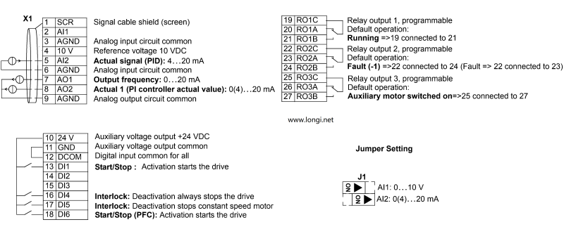
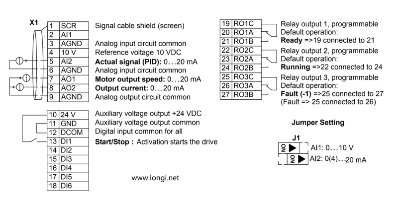
  1. 1.For voltage output instruments, such as a remote pressure gauge (range 0-10V), connect the three wires to terminals 4, 5, and 6 according to the labeling (internal resistance requirements: 1KΩ-10KΩ). Simultaneously, move the AI2 DIP switch in jumper J1 on the terminal block to the left (as shown in the diagram above). This signal represents the actual pressure feedback value.
    If it’s a current output pressure sensor, connect the two wires to terminals 5 and 6. Simultaneously, move the AI2 DIP switch in jumper J1 on the terminal block to the right (as shown in the diagram above).
  2. 2.Short-circuit terminals 11 and 12.
  3. 3.Connecting terminals 10 and 13 provides the start signal.

Parameter Settings:

99.02 6 = PID Control Macro
This parameter sets the control macro to PID, which means the device will use Proportional-Integral-Derivative control for precise regulation.

10.02 1 = DI1 Controls Start/Stop
This setting determines that Digital Input 1 (DI1) will be used to control the starting and stopping of the process or device.

11.02 7 = External 2
This parameter is likely referring to an external control source or input selection. “External 2” could be a specific configuration for an external signal or device.

13.04 20% (When the actual signal is 4-20mA or 2-10V)
This setting configures the input signal scaling. It indicates that when the incoming signal is within the range of 4-20mA or 2-10V, it will be interpreted as 20% of the full scale value.

16.01 0 – No start permissive signal required
This parameter indicates that no external permissive signal is needed to start the device or process. It’s set to 0, which means the start permissive signal is not required.

40.10 19 (Internal setpoint)
This parameter sets the internal setpoint to 19. The exact meaning of this value depends on the context and scaling of the system, but it typically represents a target value for the controlled variable.

40.11 Set pressure value (Percentage of the pressure gauge range, e.g., if the target is 8 kg and the range is 16 kg, set it to 50%)
This parameter is used to set the desired pressure as a percentage of the pressure gauge’s total range. In the example given, the target pressure is 8 kg out of a possible 16 kg range, so it’s set to 50%.

ABB Drives ACS510 One-to-Three Wiring

1.The feedback signal from the pressure sensor is of the current type. To align with this, configure J1 for current input by dialing the code to the right.

2.Establish a short circuit between pins 11 and 12.

3.Connecting pins 10 and 13 initiates the start signal.

4.For the interlocked startup of three pumps, establish connections between pin 10 and pins 16, 17, and 18 respectively.

5.Each of the three pumps should be wired to a separate relay, ensuring individual control.

VFD Parameter Settings

Parameter Set Value

99.02 6 = PID Control Macro

10.02 1 = DI1 Controls Start/Stop

11.02 7 = External 2

13.04 20% (When the actual signal is 4-20mA or 2-10V)

14.01 31 = PFC Control

14.02 31 = PFC Control

14.03 31 = PFC Control

16.01 0 – No start permissive signal required

40.10 19 (Internal setpoint)

40.11 Set pressure value (Percentage of the pressure gauge range, e.g., if the target is 8 kg and the range is 16 kg, set it to 50%)

81.17 2 = Number of auxiliary units

81.27 3 = Number of auxiliary units

Note: There seems to be a redundancy in the parameters 14.01, 14.02, and 14.03, all set to “PFC Control” and parameters 81.17 and 81.27 both referring to “Number of auxiliary units”. Please check if these are indeed distinct parameters or if some correction is needed. Additionally, ensure that the parameter names and values align with the specific model and manual of the frequency converter being used.

Posted on Leave a comment

ABB DRIVE ACS510 Constant Pressure Water Supply Control One to Two Scheme, Wiring and Parameter Settings

Take advantage of ABB’s ACS510 VSD for seamless multi-pump pressure control. With its advanced PFC application macro, you can effortlessly manage up to 7 pumps while ensuring consistent pressure regulation. This powerful feature eliminates the need for a separate constant pressure water supply controller, simplifying your system design. By implementing the SPFC macro, you can enjoy the added benefit of reducing stress on your pumps and power grid through gentle soft-start sequences. Consider SPFC as an enhanced version of PFC, providing superior control and reliability for your critical applications.

According to your description, DL6 is used for start commands, DL1 and DL2 for PFC control. SA1, SA2, and SA3 are three-position switches, with the middle position as stop. When manually operating at rated frequency, the switch is set to the right, and when the automatic allow signal is present, the switch is set to the left. The connections at 19, 21 and 22, 24 are connected to the relay terminals below the VFD, corresponding to the normally open contacts of RO1 (Relay 1) and RO2 (Relay 2).

The difference between PFC and SPFC:

In automatic mode with PFC: When SA2 and SA3 are set to the automatic position and the power is turned on, relay 1 on the inverter engages, which causes KM1 to engage and the motor M1 to start operating at variable frequency. If the frequency reaches the start-up frequency +1, the auxiliary motor is engaged, and relay 2 on the inverter engages, causing KM3 to engage and motor M2 to start operating at rated frequency. With PFC in automatic mode, it is possible to switch pumps at regular intervals.

In automatic mode with SPFC: When SA1 and SA2 are set to the automatic position and the power is turned on, relay 1 on the inverter engages, which causes KM1 to engage and the motor M1 to start operating at variable frequency. When the frequency reaches the start-up frequency +1, relay 1 is first disengaged and then relay 2 is engaged, causing KM4 to engage and motor M2 to start operating at variable frequency. Simultaneously, relay 1 re-engages to cause KM2 to engage and motor M1 to operate at rated frequency. With SPFC in automatic mode, it is not possible to switch pumps at regular intervals.

CODE NAME SET VALUE NOTES
9902 APPLIC MACRO 15=SPFC control
1002 EXT2 COMMANDS 6=DI6 VSD startup command
1102 EXT1/EXT2 SEL 7=EXT2
1106 REF2 SELECT 19=PID1OUT After SPFC takes effect, 1106 defaults to 19 and does not require adjustment
1401 RELAY OUTPUT 1 31=PFC control
1402 RELAY OUTPUT 2 31=PFC control
1403 RELAY OUTPUT 3 4=FAULT
1601 RUN ENABLE 6=DI6
2008 MAXIMUM FREQ 50HZ
2202 ACCELER TIME 1 15S Set according to actual situation
2203 DECELER TIME 1 15S Set according to actual situation
3104 AR OVERCURRENT 1=ENABLE
4001 GAIN(PID) 1.5-2
4002 INTEGRATION TIME(PID) 2.5
4009 100% VALUE ” Defines (together with 4008) the scaling Set according to actual situation
applied to the PID controller’s actual values”
4010 SET POINT SEL 0=keypad – Control panel provides reference.
4016 ACT1 INPUT 1=AI1 is ACT1(Remote transmission meter);2=AI2 is ACT1(Pressure sensor)
4022 SLEEP SELECTION 7=INTERNAL
4023 PID SLEEP LEVEL 38HZ Set according to actual situation
4024 PID SLEEP DELAY 30S
4025 WAKE-UP DEV 2.5
8118 AUTOCHNG INTERV 1h
8119 AUTOCHNG LEVEL 85%
8120 INTERLOCKS 1=DI1 Enables the Interlock function
8123 PFC ENABLE 1 = ACTIVE – Enables PFC control
8127 MOTORS 2 After SPFC takes effect, it defaults to 2, and there is no need to adjust the two pumps

The parameters mentioned in this article use SPFC macros, and PFC is also similar, except that the macro parameter is 7.VSDs such as ACS550 and ACS355 should also be able to achieve constant pressure water supply frequency converter control through similar operations. Please refer to their technical manuals for details, or contact us for guidance

Posted on Leave a comment

Global Ultrasonic Equipment Maintenance Center

Longi Electromechanical Company uses artificial intelligence AI methods and professional technical teams to professionally repair various types of ultrasonic equipment. It can achieve component level maintenance and repair general problems on the same day, winning valuable time for customer production. There are many types and brands of ultrasonic equipment devices, and currently there are a large number of ultrasonic equipment in the market, with varying quality and old and new. Rongji Electromechanical Company has repaired over 2000 related equipment and accumulated rich maintenance experience.Phone/WhatsApp:+8618028667265

Longi has excellent mechanical and electrical technology, and has great confidence in its repair level. The repaired ultrasonic welding equipment has a one-year warranty for the same problem point. The maintenance cost is relatively low, and the price is lower than the peers.

Longi Electromechanical repairs several types of ultrasonic equipment, including:

Plastic hot plate welding machines, ultrasonic welding machines, high-frequency welding machine maintenance, hot melt hot plate welding machines, multi-head ultrasonic welding machines, ultrasonic plastic welding machines, ultrasonic fusion welding machines, ultrasonic spot welding machines, hot plate welding machines, and hot melt welding machines.

Ultrasonic metal welding machines, ultrasonic metal spot welding machines, ultrasonic metal wire welding machines, ultrasonic metal roll welding machines, solar collector plate welding machines, solar copper pipe punching machines, and copper pipe flanging machines.

Automotive door panel welding machines, automotive interior part welding machines, automotive instrument panel welding machines, automotive bumper welding machines, automotive radiator welding machines, and automotive light welding machines.

Ultrasonic flaw detectors, ultrasonic welding and cutting machines, ultrasonic food cutting machines, ultrasonic tool heads, ultrasonic cutting knives, ultrasonic cake cutting machines, handheld ultrasonic welding machines, ultrasonic cleaners, KN95 mask sealing machines, semi-automatic spot welding machines for flat masks, manual mask spot welding machines, N95 mask earloop ultrasonic welding machines, ultrasonic mask sealing machines, automatic frequency tracking ultrasonic welding machines, handheld ultrasonic spot welding machines, and fully automatic ultrasonic welding machines.

Ultrasonic vibrating plates, ultrasonic power boards, ultrasonic transducers, ultrasonic generators, presses, ultrasonic boosters, ultrasonic welding heads, and supporting tooling.

Rongji Electromechanical has extensive experience in repairing and maintaining this diverse range of ultrasonic equipment, ensuring that these machines continue to operate at peak performance.

Longi Electromechanical has repaired ultrasonic equipment from various brands, including:

Minghe, Changrong, Swiss RINCO, Dingtaihengsheng, Gute, Xinzhi, Taiheda, Donghua, Ruang, American Branson, Daguangdian, Swiss TELSONIC, German SCHUNK, American AMTECH and SONICS, Korean TECHSONIC, Chuxin (SONICTECH), Jiemeng, Jikang, Hekeda, Kejiemeng, Weigute, Meiji, Fukeda, Jieda, and Haoshun.

The company’s experienced engineers are familiar with the repair and maintenance requirements of these brands, ensuring that the ultrasonic equipment is restored to its optimal performance. Rongji Electromechanical’s expertise in repairing a wide range of ultrasonic equipment brands demonstrates its versatility and reliability in the industry.
Over the years of repairing ultrasonic equipment, we have identified the following common faults:

The cleaning water surface does not vibrate, and there is debonding between the vibrator and the load.
The mold head is misaligned.
There is no display when turned on, and there is an overload or overcurrent during the welding process.
The current is too high during testing.
Insufficient welding capacity during the welding process, or the welding heat is too intense.
The vibrator has leakage waves.
The button does not work when pressed.
There is an issue with the travel protection.
There is sound, but the power cannot be adjusted.
The ultrasonic intensity is insufficient.
The transducer ceramic is cracked.
The power tube is burned out.
The voltage stabilization part is not functioning properly.
There are problems with the inductor and isolation transformer.
The vibrator wire is disconnected.
These faults can occur due to various reasons such as wear and tear, improper use, or component failures. It is important to regularly inspect and maintain ultrasonic equipment to identify and address these issues promptly. Our team of experienced engineers at Rongji Electromechanical is well-versed in diagnosing and repairing these common faults, ensuring that your ultrasonic equipment is restored to its optimal performance.
Principles for Ultrasonic Equipment Repair:

  1. Observe first, understand next, and then act, from the outside in.

When encountering problems with ultrasonic equipment, one should not blindly continue operating or rush to take action. It is essential to first inquire with the frontline production staff on duty that day to understand clearly when the problem occurred and the actual fault situation. Check if there were any voltage fluctuations, thunderstorms, or unauthorized disassembly at the scene.

If there is no response from the equipment, it is likely that a fuse or short circuit has occurred. In this case, focus on checking the electrical situation and measuring impedance with a multimeter. For unfamiliar ultrasonic equipment, do not dismantle it immediately. It is necessary to research its structure and related manuals online. When disassembling, pay attention to the coordination process of each part, keep the parts organized, and label anything that needs to be remembered. If necessary, draw simple diagrams. Acting rashly may escalate the problem or even make it impossible to reassemble the equipment.

  1. Simple before complex

Start by ruling out peripheral issues. Factors such as the surrounding environment, electricity, load, raw materials, and molds can all affect the normal operation of the equipment. First, confirm whether these aspects are functioning properly. Clean the equipment and its environment, as this sometimes resolves the issue. For example, oil and dust on some buttons can cause poor contact. If possible, swap two ultrasonic devices or other components for comparison to confirm the problem’s general direction. Only after confirming that the ultrasonic device itself is the issue should you disassemble it or send it out for repair.

For equipment that has had problems in the past, there is a high likelihood of similar failures recurring, so pay close attention to these areas.

  1. Address mechanical issues first

Mechanical problems can be seen with the naked eye, such as issues with the mold. Even if the transducer is working, the equipment may not function properly, which can be determined through touch and comparison. If mechanical problems are not addressed and one blindly searches for electrical causes, it will be like looking for a needle in a haystack and will never be resolved. Admittedly, dealing with mechanical issues can be somewhat challenging, but they must be resolved.

Posted on Leave a comment

Global Instrument Maintenance Center

Intelligent Precision Instrument Maintenance Base,Professional maintenance of various intelligent instruments and meters, phone/WhatsApp:+8618028667265, Mr. Guo

Longi Electromechanical specializes in repairing various imported intelligent precision instruments and meters, and has accumulated rich maintenance experience over the years, especially environmental testing instruments, electrical instruments, thermal instruments, acoustic and flow instruments, and electrical instruments. Environmental testing instruments, thermal instruments, acoustic and flow instruments,
We can quickly repair radio instruments, length instruments, environmental testing equipment, quality inspection instruments, etc.
Different instruments have different characteristics and functions, and their circuits and structures are also different. Even for the same instrument, if there are different faults, repairing them is still a different solution. Rongji Company has numerous high-end maintenance engineers equipped with artificial intelligence AI detection instruments, which can provide you with multi-dimensional solutions to various tricky instrument problems.

Over the years, Longi Electromechanical has repaired instruments including but not limited to:

Spectrum analyzers, network analyzers, integrated test instruments, 3D laser scanners, noise figure testers, receivers, telephone testers, high and low-frequency signal sources, audio and video signal analyzers, constant temperature and humidity chambers, thermal shock chambers, simulated transport vibration tables, mechanical vibration tables, AC grounding impedance safety testers, safety comprehensive analyzers, withstand voltage testers, battery internal resistance testers, high-precision multimeters, precision analyzers, gas and liquid analyzers, metal detectors, LCR digital bridges, oscilloscopes, electronic loads, power meters, power analyzers, multimeters, DC power supplies, AC power supplies, CNC power supplies, variable frequency power supplies, and various communication power supplies.

We have repaired the following brands:

Chroma, ITECH, Tonghui, Agilent, Tektronix, Keysight, Fluke, Keithley, Rohde & Schwarz, Lecroy, Anritsu, Rigol, and many more.

Longi Electromechanical strives to provide comprehensive repair services for a wide range of instruments and equipment, ensuring that our customers’ devices are restored to optimal performance.
Longi maintenance engineers possess over twenty years of experience in instrument repair. We have multiple engineers who excel in repairing imported precision instruments. The team works together, enabling faster troubleshooting and quick resolution of complex issues while improving the repair rate of instruments.

Spare parts are fundamental to successful repairs. Many imported instruments and meters require specialized components that cannot be easily replaced with generic market parts. Rongji Electromechanical maintains a long-term stock of electronic components for various instruments, ensuring their availability when needed.

Documentation and manuals are also crucial tools for ensuring rapid repairs. Accessing these resources allows for quick research and analysis of faults, enabling engineers to quickly identify the repair priorities. Longi Electromechanical has a long history of collecting specifications for various brands and models of instruments, greatly aiding in the repair process.

The intelligent instruments that have been carefully repaired by us can generally continue to be used for about 5 years. We promise that when the same malfunction occurs again, our repair service will provide a one-year warranty service.

Posted on Leave a comment

Global Touch Screen Repair Centers,Professional maintenance touch screen

Touch screen is a special human-machine dialogue device that has been widely used in daily life, production, and commercial occasions. Touch screens are mainly divided into several forms: resistive screens, capacitive screens, infrared screens, and ultrasonic screens. Because it has too close contact with people and a large part of it is a vitreous structure, the probability of touch screen damage is relatively high. The most common area of damage to touch screens is often the surface touch outer screen, commonly known as the “touchpad,” which can be used normally after replacement.
Rongji Electromechanical Maintenance has been using touch screens in the industrial, commercial, medical, and military fields for over 20 years. Currently, in these areas, resistance screens are mostly used due to reliability and safety considerations. The automotive industry uses both resistive and capacitive screens, and touch screens in this field, whether they are capacitive or resistive, can be repaired by us.

Step 1: Remove the back cover and remove the motherboard screws

Touch screen manufacturers, considering profit, often design touch panels and even LCD components as non-standard products, and do not disclose the drivers and circuits to the public. If standard touch panels and controllers are installed, they are often not compatible.

Step 2: Remove the outer shell and use a hair dryer to heat up the film

Longi Electromechanical Company has a team of engineers who have been researching the reverse engineering of various touch screens for a long time. They have explored a solution and replacement process for touch screen accessories from the bottom layer or touch panel technology. They can perfectly use the touch panel and other accessories produced by Longi Company to replace the original ones, and solve problems for customers while significantly reducing maintenance costs.

Step 3: Peel off the film and remove the touchpad

Most resistive screens and a small portion of capacitive screens can be purchased from touch pads produced by Longi Company. Following the replacement method we provide, they can be installed and used normally.

Step 4: Apply double-sided tape to the touch screen border and place a new touch pad on it

A small number of resistive screens and some capacitive screens, due to their special design, customers can send the entire touch screen to Rongji Company by mail. We use professional software analysis and judgment, and through hardware processing and software patching methods, we can achieve cracking and replacement.

Step 5: Install the motherboard LCD and flip it over to test if the touchpad is functioning properly

Similarly, for accessories such as LCD, high-voltage bars, and light tubes, similar methods can be used to achieve functional repair of touch screens without affecting their use.

Step 6: After successful testing, apply the film and replace the touchpad

During the use of touch screens, in addition to the mentioned accessory issues, there may also be circuit failures such as power boards or motherboards. For example, it is not displayed, or the display is abnormal. This situation belongs to a hardware malfunction of the circuit. The entire machine can be sent to the headquarters of Longi Company by mail, and we will use circuit maintenance methods for repair.

A special situation is when there is a problem with the touch screen software, such as the battery running out or data being lost. This situation is quite troublesome. If the customer has backed up data, we can help them re-enter it and it can be used normally. If the customer does not have backup data and cannot contact the equipment manufacturer to find the data, the only solution is to rewrite the appropriate touch screen program according to the process and equipment flow. As touch screens are secondary development applications, the programming difficulty is not too high. However, it will take time to pair with other devices in the system, such as PLCs.

Longi Electromechanical Company has repaired the following brands of touch screens:

Siemens touch screens, Proface touch screens, Mitsubishi touch screens, Fuji touch screens, Panasonic touch screens, OMRON touch screens, WEINVIEW touch screens, Koyo touch screens, Delta touch screens, Toyota JAT touch screens for air-jet looms, Staubli touch screens, Beijer touch screens, AB (Allen-Bradley) Rockwell touch screens, Hitech touch screens, Schneider touch screens, Toyo touch screens, DMC touch screens, MCGS (Kunlun Tongtai) touch screens, Touchwin touch screens, General touch screens, Red Lion touch screens, B&R (Beckhoff & Rautert) touch screens, LG touch screens, M21 touch screens, Fatek (Yonghong) touch screens, IDEC (Waizu) touch screens, Wecon touch screens, Pingtong touch screens, Fanuc touch screens, Lenze touch screens, Advantech touch screens, Hakko touch screens, Yushin touch screens, UNIOP touch screens, Shihlin (See) touch screens, Parker touch screens, Eura touch screens, and Hakko White Light touch screens, among others.

Please note that some of the brand names mentioned may be trademarks or registered trademarks of their respective companies. The listing here is for informational purposes only and does not imply any affiliation or endorsement by Longi Electromechanical Company or any of the mentioned brands.

Common Touch Screen Issues:

Display is visible but cannot be touched or clicked, or the touch response is poor. In most cases, this is due to a faulty touch panel. Sometimes recalibrating can solve the problem, but mostly the touch panel needs to be replaced.

The touch screen does not display anything, and even the indicator lights are not on. This situation usually indicates a problem with the power supply unit of the touch screen.

The touch screen functions but displays a black screen, while the indicator lights are normal. This is typically caused by a burned-out backlight tube inside the screen.

The touch screen displays a distorted image or abnormal colors. This is often a problem with the liquid crystal display (LCD) or could be caused by issues with the connecting cables.

The touch screen displays a communication error, and the response to touch is very slow. This issue is not with the touch screen itself but rather with the connection between the Programmable Logic Controller (PLC) or other devices and the touch screen. In many cases, the problem lies with the connecting cables or plugs.

Posted on Leave a comment

Global Servo CNC maintenance center

Global Servo CNC maintenance center,Professional maintenance of servo CNC systems

Remember to contact Longi Electromechanical for any issues with servo and CNC systems!

Servo systems differ from VFDs in that they offer higher precision and typically come with delicate encoders. Servo motors are synchronous motors with magnets inside, and if not handled carefully during disassembly and assembly, their original performance may not be restored. Additionally, different servo drivers cannot be used interchangeably with other servo motors. This means that during the repair of a servo driver, a corresponding servo motor and cable plug are required for proper testing. Similarly, repairing a servo motor also requires a matching servo driver for testing, which can pose challenges for many maintenance personnel.

As for CNC (Computer Numerical Control) systems, most are embedded industrial computer types with closed control systems. Each manufacturer has its own design ideas, programming methods, wiring, and communication architectures, making them incompatible with one another.

Longi Electromechanical Company has designed various styles of servo and CNC maintenance test benches to test the working conditions of different CNC systems, servo drivers, or servo motors. When servo systems encounter issues such as no display, phase loss, overvoltage, undervoltage, overcurrent, grounding, overload, module explosion, magnet loss, parameter errors, encoder failures, communication alarms, etc., the corresponding platform can be used to test and diagnose the problem.

Repair Hotline: +8618028667265 Mr. Guo

After resolving these issues, the servo system also needs to undergo a simulated load test to avoid problems such as overcurrent under load conditions, even if it performs well under no-load conditions. This ensures that the servo system is fully functional and ready for use in actual applications.

For the CNC system, it is also necessary to conduct simulated operation before normal delivery to avoid any discrepancy with the on-site parameters. Currently, Rongji Electromechanical possesses hundreds of servo and CNC test benches, which can quickly identify problem areas and promptly resolve issues. With these advanced testing facilities, Longi Electromechanical ensures the smooth operation and reliability of the repaired equipment.

The Servo and CNC Repair Center established by Longi Company currently has over 20 skilled and experienced maintenance engineers who specialize in providing repair services for different brands and specifications of servo and CNC systems. They implement tailored repair solutions for different maintenance projects, ensuring efficient and high-quality service for customers. By helping customers save valuable production time and reducing their maintenance costs, Rongji truly cares about the urgent needs of its customers and strives for common development and progress together.

We have repaired the following brands of servo and CNC systems:

Servo Systems

  • Lenze Servo Systems
  • Siemens Servo Systems
  • Panasonic Servo Systems
  • Eurotherm Servo Systems
  • Yaskawa Servo Systems
  • Fuji Servo Systems
  • Delta Servo Systems
  • Omron Servo Systems
  • Fanuc Servo Systems
  • Moog Servo Systems
  • TECO Servo Systems
  • Norgren Servo Systems
  • SSB Servo Drive Systems
  • Hitachi Servo Systems
  • Toshiba Servo Systems
  • Denso Servo Systems
  • Parvex Servo Systems

CNC Systems

  • Mitsubishi Servo Systems
  • Sanyo Servo Systems
  • Mitsubishi CNC (MITSUBISHI)
  • Fanuc CNC (FANUC)
  • Siemens CNC (SIEMENS)
  • Brother CNC (BROTHER)
  • Mazak CNC (MAZAK)
  • GSK (Guangzhou Numerical Control)
  • Huazhong Numerical Control
  • Fagor CNC
  • Heidenhain
  • Haas CNC
  • NUM (France)
  • Hurco (USA)
  • KND (Beijing KND Technology Co., Ltd.)
  • Leadshine
  • Syntec
  • Shenyang Machine Tool i5
    *凯恩帝 (KND)

Note: Some of the brand names mentioned may be trademarks or registered trademarks of their respective owners. The listing here is for informational purposes only and does not imply any affiliation or endorsement by Rongji Electromechanical or any of the mentioned brands.

Machine Tool Brands

(1) European and American Machine Tools:

  • Gildemeister
  • Cincinnati
  • Fidia
  • Hardinge
  • Micron
  • Giddings
  • Fadal
  • Hermle
  • Pittler
  • Gleason
  • Thyssen Group
  • Mandelli
  • Sachman
  • Bridgeport
  • Hueller-Hille
  • Starrag
  • Heckert
  • Emag
  • Milltronics
  • Hass
  • Strojimport
  • Spinner
  • Parpas

(2) Japanese and Korean Machine Tools:

  • Makino
  • Mazak
  • Okuma
  • Nigata
  • SNK
  • Koyo Machinery Industry
  • Hyundai Heavy Industries
  • Daewoo Machine Tool
  • Mori Seiki
  • Mectron

(3) Taiwanese and Hong Kong Machine Tools:

  • Hardford
  • Yang Iron Machine Tool
  • Leadwell
  • Taichung Precision Machinery
  • Dick Lyons
  • Feeler
  • Chen Ho Iron Works
  • Chi Fa Machinery
  • Hunghsin Precision Machinery
  • Johnford
  • Kaofong Industrial
  • Tong-Tai Machinery
  • OUMA Technology
  • Yeongchin Machinery Industry
  • AWEA
  • Kaoming Precision Machinery
  • Jiate Machinery
  • Leeport (Hong Kong)
  • Protechnic (Hong Kong)

(4) Chinese Mainland Machine Tools:

  • Guilin Machine Tool
  • Yunnan Machine Tool
  • Beijing No.2 Machine Tool Plant
  • Beijing No.3 Machine Tool Plant
  • Tianjin No.1 Machine Tool Plant
  • Shenyang No.1 Machine Tool Plant
  • Jinan No.1 Machine Tool Plant
  • Qinghai No.1 Machine Tool Plant
  • Changzhou Machine Tool Factory
  • Zongheng International (formerly Nantong Machine Tool)
  • Dahe Machine Tool Plant
  • Baoji Machine Tool Plant
  • Guilin No.2 Machine Tool Plant
  • Wanjia Machine Tool Co., Ltd.
  • Tianjin Delian Machine Tool Service Co., Ltd.

Note: The list provided above is comprehensive but not exhaustive. Machine tool brands and manufacturers are constantly evolving, and new players may have emerged since the compilation of this list. Always refer to the latest industry updates for the most accurate information.

Posted on Leave a comment

Global Variable Frequency Drive (VFD) repair center

“Longi Electromechanical” has more than 20 years of experience in industrial control maintenance, and is one of the earliest companies engaged in VFD repair. Equipped with artificial intelligence AI maintenance instruments, it specializes in emergency repair of various equipment, with high technical efficiency. It has repaired more than 200,000 units of equipment, including ultrasonic, robot, charging pile, inverter,Variable Frequency Drive (VFD), touch screen, servo, intelligent instrument, industrial control machine, PLC and other products. General problems can be repaired on the same day. LONGI promises you that “if it can’t be repaired, we won’t charge you”. And it provides lifelong maintenance service and free technical consultation for inspection! For urgent repair consultation, please call the contact number or add WHATSAPP maintenance hotline: +8618028667265 Mr. Guo

From European and American brands to Japanese, Korean, and Taiwanese ones, until various domestic brands, we have repaired countless models and specifications of VFDs. In the process of serving our customers, we have continuously learned and accumulated maintenance experience to enhance our skills. We specialize not only in repairing VFDs but also in summarizing various maintenance experiences, elevating them to a theoretical level. We have published the book “VFD Maintenance Technology” and offered VFD maintenance training, thereby promoting the development of the VFD maintenance industry. Longi Electromechanical Company has repaired VFDs from the following brands:

European and American Brands

ABB drives, SEW drives, LUST VFD, LENZE VSD, Schneider drives, CT drives, KEB VSD, Siemens drives, Eurotherm VFD, G.E. VFD, VACON VSD, Danfoss VFD, SIEI VFD, AB VFD, Emerson VFD, ROBICON VFD, Ansaldo VFD, Bosch Rexroth VSD, etc.

Japanese Brands:

Fuji INVERTER, Mitsubishi INVERTER, Yaskawa INVERTER, Omron INVERTER, Panasonic INVERTER, Toshiba INVERTER, Sumner INVERTER, Tooka INVERTER, Higashikawa INVERTER, Sanken INVERTER, Kasia INVERTER, Toyo INVERTER, Hitachi INVERTER, Meidensha INVERTER, etc.

Taiwanese Brands:

Oulin INVERTER, Delta INVERTER, Taian INVERTER, Teco INVERTER, Powtran INVERTER, Dongling INVERTER, Lijia INVERTER, Ningmao INVERTER, Sanji INVERTER, Hongquan INVERTER, Dongli INVERTER, Kaichi INVERTER, Shenghua INVERTER, Adlee INVERTER, Shihlin INVERTER, Teco INVERTER, Sanchuan INVERTER, Dongweiting INVERTER, Fuhua INVERTER, Taian INVERTER (note: Taian is repeated, possibly a mistake in the original list), Longxing INVERTER, Jiudesongyi INVERTER, Tend INVERTER, Chuangjie INVERTER, etc.

Chinese Mainland brands:

Senlan Inverter, Jialing Inverter, Yineng Inverter, Hailipu Inverter, Haili Inverter, Lebang Inverter, Xinnuo Inverter, Kemron Inverter, Alpha Inverter, Rifeng Inverter, Shidai Inverter, Bost Inverter, Gaobang Inverter, Kaituo Inverter, Sinus Inverter, Sepaxin Inverter, Huifeng Inverter, Saipu Inverter, Weier Inverter, Huawei Inverter, Ansheng Inverter, Anbangxin Inverter, Jiaxin Inverter, Ripu Inverter, Chint Inverter, Delixi Inverter, Sifang Inverter, Geli Te Inverter, Kangwo Inverter, Jina Inverter, Richuan Inverter, Weikeda Inverter, Oura Inverter, Sanjing Inverter, Jintian Inverter, Xilin Inverter, Delixi Inverter, Yingweiteng Inverter, Chunri Inverter, Xinjie, Kemron-Bong Inverter, Nihonye Inverter, Edison Inverter

Other brands:
Migao VFD, Rongqi VFD, Kaiqi VFD, Shiyunjie VFD, Huichuan VFD, Yuzhang VFD, Tianchong VFD, Rongshang Tongda VFD, LG VFD, Hyundai VFD, Daewoo VFD, Samsung VFD, etc.

Longi Electromechanical Company specializes in the maintenance of VFDs and strictly requires its engineers to followlow standard operating procedures. Upon receiving a unit, the engineers carefully inspect its exterior and clarify any fault conditions with the customer before beginning work. Any removed circuit boards are cleaned using ultrasonic cleaning equipment. Repaired circuit boards are coated with high-temperature and high-pressure-resistant insulating paint, dried in a drying machine, and then reinstalled in the VFD, with measures taken to prevent corrosion and interference.

The repaired VFD will undergo a simulated operation with load using a heavy-load test bench to avoid any potential issues that may arise under actual load conditions on site.

When it comes to VFD maintenance, most cases are related to the equipment on site. Sometimes a standalone unit may have been repaired, but it doesn’t work properly when installed on site. In some cases, the problem lies with the system rather than the VFD itself. For such issues, if the customer requests on-site service, we will do our utmost to resolve the problem for them. If the location is far away, such as in another province, we can use tools like video conferencing and phone calls to allow our engineers to remotely diagnose and resolve the on-site issues for the customer.

Posted on Leave a comment

Debugging of ABB VFD for ACS800 Enhancement

A. Motor Auto-tuning (Quick Debugging Steps)

  1. Power On: Ensure the system is powered on.
  2. Input Initialization:
    • Press PAR to select the language. Set 99.1 to ENGLISH.
    • Choose the application macro. Set 99.2 to CRANE.
    • Determine if parameters should be reset to factory defaults. Set 99.3 to YES or NO.
    • Select the motor control mode in 99.4: DTC (Direct Torque Control) or SCALAR.
    • Enter the rated voltage in 99.5 V.
    • Input the rated current in 99.6 A.
    • Specify the rated frequency in 99.7 HZ.
    • Set the motor’s rated speed in 99.8 RPM.
    • Define the motor’s rated power in 99.9 KW.
  3. Motor Identification Run:
    • Proceed to motor identification by selecting 99.10.
    • Generally, choose ID MAGN (the motor won’t rotate).
    • For STANDARD mode (motor rotates), the motor must be disconnected from the equipment.
    • In REDUCED identification mode (motor rotates), the motor remains connected.
    • After selecting the identification mode, a “WARNING” signal may appear.
    • Press the start button to begin motor identification. This process can be stopped at any time using the stop button.
    • Once the motor identification is complete, press RESET to enter actual signal display mode.
  4. Motor Direction Check: Verify the motor’s rotation direction using the control panel.
  5. Input Speed Limits and Acceleration/Deceleration Times: Enter the necessary parameters.

B. Parameter Configuration – Optimized for Google SEO

  1. Set parameter 10.1 to DI1 for brake acknowledgment digital input.
  2. Leave parameter 10.2 as NOT SEL for zero-position digital input.
  3. Parameter 10.3 remains NOT SEL for deceleration digital input.
  4. Parameter 10.4 is NOT SEL for rapid stop digital input.
  5. Parameter 10.5 is NOT SEL for power-on acknowledgment digital input.
  6. Keep parameter 10.6 as NOT SEL for synchronization request digital input.
  7. Set parameter 10.7 to EXT DI1.1 for chopper fault digital input.
  8. Configure parameter 10.8 to DI2 for the second speed level digital input.
  9. Set parameter 10.9 to DI5 for the third speed level digital input.
  10. Parameter 10.10 is set to DI6 for the fourth speed level digital input.
  11. Parameters 10.11 to 10.15 and 10.17, 10.18 remain NOT SEL.
  12. Set parameter 10.16 to DI-1L for fault reset digital input.
  13. Parameter group 13 deals with analog input signals. No need for modification.
  14. Set parameter 14.1 to BRAKE LIFT for relay output 1.
  15. Configure parameter 14.2 to WATCHDOG-N for relay output 2.
  16. Parameter 14.3 is set for relay output 3 to indicate a FAULT-N signal. When a fault occurs, the relay releases, and during power-on, the fault relay engages.
  17. Parameter group 15 covers analog output signals. No modifications required.
  18. Parameter group 16 deals with password settings. No need to change.
  19. Parameter group 20 defines limit values:
    • Parameter 20.1: Minimum speed for the operating range.
    • Parameter 20.2: Maximum speed for the operating range.
    • Parameter 20.3: Maximum output current.
    • Parameter 20.4: Maximum positive output torque.
    • Parameter 20.5: Maximum negative output torque.
    • Parameter 20.6: DC overvoltage controller.
    • Parameter 20.7: DC undervoltage controller.
    • Parameter 20.8: Minimum frequency for the operating range.
    • Parameter 20.9: Maximum frequency for the operating range.
    • Parameters 20.10 to 20.13 relate to analog inputs but are not detailed here.
  20. Parameter 21.1 is not to be changed.
  21. Set parameter 21.2 for the field excitation time, approximately 4 times the motor’s rated KW (in milliseconds).
  22. Parameter group 23 covers speed control gains, integral and derivative times, motor slip, etc. Generally left unchanged.
  23. Parameter group 24 deals with torque build-up time. Typically not modified.
  24. Parameter group 26 allows compensation voltage setting for the motor (only in SCALAR mode).
  25. Parameter group 27 configures the braking chopper:
    • Set parameter 27.1 to ON for brake chopper control.
    • Parameter 27.2 is set to FAULT to activate overload protection for the braking resistor.
    • Enter the actual value for the braking resistor in parameter 27.3.
    • Set the time constant for the braking resistor in parameter 27.4 to 300S.
    • Define the maximum continuous braking power for the resistor in parameter 27.5.
    • Set the control mode for the brake chopper control to AS GENERATOR in parameter 27.6.
  26. Parameter group 28 deals with motor modeling. Typically not modified.
  27. Parameter group 30 covers fault functions. Generally left unchanged.
  28. Parameter group 50 configures encoder values:
    • Set the number of encoder pulses in parameter 50.1.
    • Define the calculation method for encoder pulses in parameter 50.2.
    • Parameter 50.3 is set to FAULT for encoder fault action.
    • Set the encoder monitoring delay time in parameter 50.4 (avoid setting to 0).
    • Parameter 50.5 determines the encoder feedback usage, typically set to TRUE.
  29. Parameter group 60 handles the switch between local and external operation.
  30. Parameter groups 61 and 62 deal with speed monitoring. Generally not modified.
  31. Parameter group 63 covers torque monitoring. Typically left unchanged.
  32. Parameter group 64 is for crane mode:
    • Set parameter 64.1 to TRUE for STAND ALONE mode.
    • Parameter 64.10 is configured to STEPJOYST or STEPRADIO.
    • Parameters 64.13 to 64.16 define the speeds for the four speed levels (as a percentage of rated speed).
  33. Parameter group 65 deals with motor field current settings. Generally not modified.
  34. Parameter group 66 covers torque verification, typically left unchanged.
  35. Parameter group 67 configures brake control:
    • Set the brake application time to 0.5S in parameter 67.1.
    • Define the brake fault delay as 0.5S in parameter 67.2.
    • Parameters 67.3 to 67.10 are not detailed but can be set as needed.
  36. Parameter group 68 is for power optimization, typically not modified.
  37. Parameter group 69 defines the maximum speed and acceleration/deceleration times.
  38. Parameter group 98 activates optional modules.