Posted on Leave a comment

INVT Servo SV-DA200 Series Manual User Guide

I. Implementation of Servo JOG Jogging Operation

Implementation Process

Servo JOG (Jogging) operation allows users to manually control the servo motor for short, small movements, primarily used for debugging or precise positioning. The following are the specific steps to implement servo JOG operation:

1. Hardware Connection

  • Connect the Servo Motor: Ensure the servo motor is properly connected to the servo drive, and check that all connecting cables are secure.
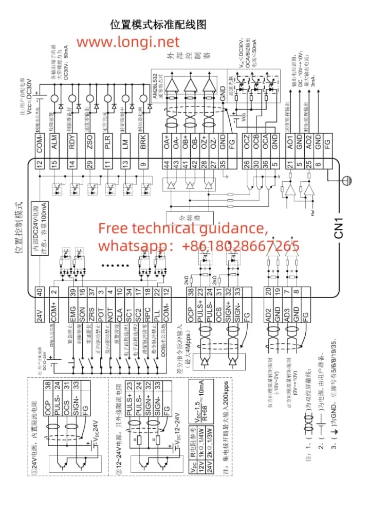
  • Control Signal Wiring: According to the CN1 terminal wiring diagram for the DA200 series servo drive, connect the control signal wires to the corresponding CN1 terminals on the servo drive. For JOG operation, typically, servo enable (SON), direction control (e.g., POT, NOT), and jog signal lines need to be connected.

2. Parameter Settings

  • Set the Motor Model: Use parameter P0.001 to set the correct motor model to ensure the drive can recognize the connected motor.
  • Configure JOG-related Parameters:
    • Jogging Speed: Set the jogging speed through parameter P0.05, typically in units of r/min.
    • Digital Input Configuration: In the P3.xx series of parameters, configure the digital input functions for servo enable (SON), forward jog (e.g., FJOG), reverse jog (e.g., RJOG), and other related inputs as needed.

3. Software Operation

  • Enable the Servo: Activate the servo drive by providing a valid signal to the servo enable terminal (SON).
  • Execute JOG Operation: Apply a forward jog (FJOG) or reverse jog (RJOG) signal, and the servo motor will move at the set jogging speed. Control the duration of the jog signal to manage the motor’s movement distance.

Precautions

  • Ensure safety during JOG operations to prevent accidental movements that could cause harm.
  • Check all connecting cables and parameter settings to ensure correct operation.
SV-SD200 Position Mode Standard Wiring Diagram

II. Servo Positioning via External Pulses in Position Control Mode

Implementation Process

In position control mode, precise servo positioning through external pulse signals is a common application. The following are the implementation steps:

1. Hardware Connection

  • Pulse Signal Lines: Connect the pulse signal lines to the pulse input terminals on the servo drive (e.g., PULS+, PULS- on CN1). Depending on requirements, direction signal lines (SIGN+, SIGN-) may also need to be connected.
  • Encoder Feedback Lines (if required): If encoder feedback is used, connect the encoder cables correctly to the corresponding terminals on the servo drive.

2. Parameter Settings

  • Control Mode Selection: Set parameter P0.03 to 0 for position control mode.
  • Pulse Input Configuration:
    • Configure the pulse input form (e.g., differential input or open-collector output) and direction signal settings.
    • Set the electronic gear ratio (e.g., P0.25, P0.26) to convert external pulses into actual motor shaft movements.
  • Position Control-related Parameters:
    • Adjust position loop gains (e.g., P2.02) and other control parameters as needed.
    • Configure software limits (e.g., P0.35, P0.36) to prevent exceeding safe travel ranges.

3. Software Operation

  • Send Pulse Signals: Transmit pulse signals to the servo drive via an upper computer, PLC, or other control system. The number of pulses determines the motor’s movement distance, while the pulse frequency controls the motor’s speed.
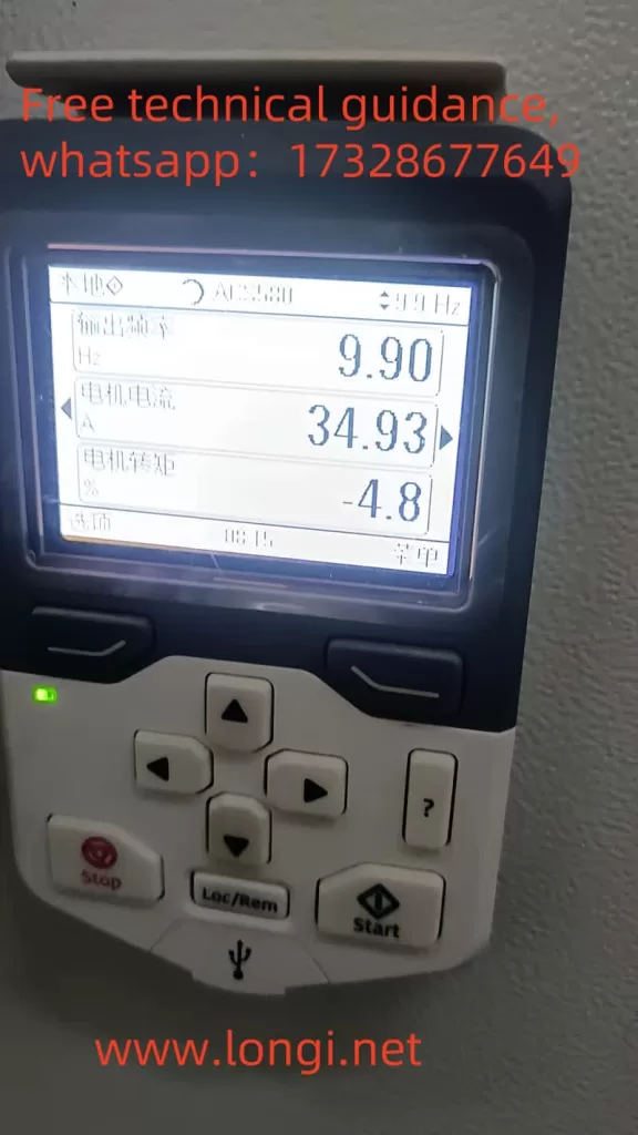
  • Monitor Status: Use the servo drive’s display panel or upper computer software to monitor the servo motor’s actual position and speed.

Precautions

  • Ensure pulse signal quality and stability to prevent positioning inaccuracies due to signal interference.
  • Adjust control parameters according to actual needs to achieve optimal control performance.

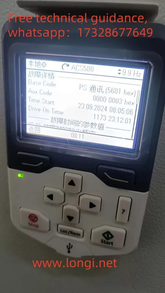
III. Fault Code Meanings and Solutions

Common Fault Codes and Solutions

  • Er10-4: Emergency Stop
    • Meaning: The emergency stop signal is active.
    • Solution: Check if the emergency stop button or related input signal lines have been triggered accidentally, clear the fault, and re-enable the servo.
  • Er22-0: Position Deviation Fault
    • Meaning: The actual position deviates significantly from the command position.
    • Solution: Inspect the mechanical transmission components for jams or loose connections, adjust position loop gains and other control parameters as needed.
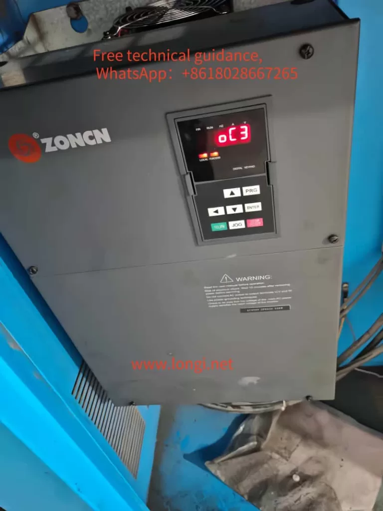
  • Er25-1: Overcurrent Fault
    • Meaning: The motor current exceeds the rated value.
    • Solution: Check if the motor is overloaded, adjust speed or torque loop gains, and ensure the power supply voltage is stable.
  • Er13-1: Undervoltage Fault
    • Meaning: The main circuit supply voltage is too low.
    • Solution: Verify the power supply voltage, troubleshoot line faults, or adjust the power supply voltage.

Precautions

  • When encountering fault codes, first consult the fault code table for specific meanings and then follow the corresponding solutions for troubleshooting.
  • If faults cannot be resolved, promptly contact technical support or professional maintenance personnel for assistance.

By following the steps and precautions outlined above, users can effectively implement INVT Servo DA200 series JOG jogging operation, position control using external pulses, and fault diagnosis and resolution.

Posted on Leave a comment

Schneider VFD ATV630(altivar 630): Analysis and Troubleshooting of Input Phase Loss and NLP Faults

The Schneider VFD ATV630(altivar 630) is a crucial device in the field of industrial automation, and its stable operation is vital for the efficiency of production lines. However, in practical applications, the ATV630 VFD may sometimes encounter Input Phase Loss and No Line Power (NLP) faults. This article will provide a detailed analysis of the causes of these two faults and corresponding troubleshooting methods.

Schneider inverter fault NLP

I. Input Phase Loss Fault

  1. Fault Phenomenon

The Input Phase Loss fault typically manifests as the VFD detecting a lack of one or more phases in the input power supply, leading to the inability of the VFD to operate normally.

  1. Causes

Power supply issues: Incorrect power supply connected to the VFD, such as connecting a single-phase power supply to a three-phase VFD.
Blown fuse: The fuse on the input side of the VFD may trip due to overcurrent or short circuit.
Unbalanced load: Unbalanced three-phase load may also result in phase loss faults.
Hardware failure: The internal detection circuit of the VFD may malfunction.
3. Troubleshooting Methods

Check power connection: Ensure that the VFD is connected to the correct three-phase power supply with stable voltage.
Inspect fuse: Check the condition of the fuse on the input side and replace it if necessary.
Balance load: Adjust the load to ensure balanced three-phase loading.
Contact after-sales service: If internal VFD failure is suspected, contact the supplier for after-sales repair.

Physical picture of ATV630 VFD

II. NLP Fault

  1. Fault Phenomenon

The NLP fault indicates that the VFD has no main power supply voltage, i.e., the VFD does not detect main power input.

  1. Causes

Main power not connected: Only the 24V power supply is provided to the control terminals of the VFD, but the main circuit power supply is not connected.
Low voltage: The main circuit voltage is lower than the rated voltage of the VFD.
Hardware failure: The rectifier section of the VFD or components for detecting voltage may malfunction.
DC reactor not connected: For some high-power VFDs, if the DC reactor is not correctly connected, it may also lead to NLP faults.
3. Troubleshooting Methods

Check main power: Use a multimeter to check if the input voltage of the main circuit is normal.
Measure DC voltage: Use the DC range of the multimeter to measure the voltage between the PA/+ and PC/- terminals to ensure that the DC bus voltage is normal. If it is low, there may be a fault in the rectifier section of the VFD.
Check monitoring menu: View the main power supply voltage in the monitoring menu. If it is abnormal, it may be due to a failure of the internal voltage detection components of the VFD.
Inspect DC reactor: For VFDs equipped with a DC reactor, ensure that it is correctly connected.

III. Preventive Measures
To avoid similar issues, it is recommended to regularly maintain and inspect the VFD to ensure it is in good working condition. Specific measures include:

Regularly check power connections: Ensure that power connections are secure without looseness or corrosion.
Monitor voltage changes: Regularly monitor changes in power supply voltage to ensure it remains stable within the range allowed by the VFD.
Balance load: Arrange the load reasonably to avoid problems caused by unbalanced three-phase loading.
Professional repair: For complex faults, contact a professional VFD repair service provider for handling.

In summary, when the Schneider VFD ATV630(altivar 630) encounters Input Phase Loss and NLP faults, the causes should be analyzed first, followed by troubleshooting and repair according to the corresponding methods. Meanwhile, regular maintenance and inspections can effectively prevent the occurrence of similar faults, ensuring the stable operation of the VFD.

Posted on Leave a comment

Operating Instructions for Invt IPE100 Series Engineering Inverter Manual

I. Introduction to Operation Panel Functions

The Invt IPE100 Series Engineering Inverter is equipped with an intuitive and user-friendly operation panel, featuring the following key functions:

  1. PRC/ESC (Program/Escape Key): Used to enter or exit the primary menu and delete quick parameters. This key facilitates menu navigation and parameter management during programming or debugging.
  2. DATA/ENT (Enter Key): Navigates through menu screens level by level and confirms parameter settings. It is essential for making and modifying parameter settings.
  3. ↑ (Up Key): Increments data or function codes. Used to conveniently increase numerical values when adjusting parameters.
  4. ↓ (Down Key): Decrements data or function codes. Corresponds to the Up Key for decreasing parameter values.
  5. 》/SHIFT (Shift Key): Cycles through display parameters in both stop and run display modes. During parameter modification, it selects specific digits for editing, providing flexibility in parameter editing.
  6. RUN (Run Key): Initiates inverter operation in keyboard control mode. It is a primary control for the inverter’s running state.
  7. STOP/RST (Stop/Reset Key): Halts inverter operation during runtime. In fault alarm states, it resets faults regardless of function code P7.04 settings.
  8. QUICK/JOG (Quick/Jog Key): Its function is determined by function code P7.03. When P7.03=0, it activates jogging mode (keyboard control only); when P7.03=1, it toggles between forward and reverse rotation (keyboard control only). Simultaneous pressing of RUN and STOP/RST keys initiates a free stop.
Operation Panel Function Diagram of Invt IPE100 Inverter

II. Terminal Start and External Potentiometer Speed Control Setup

  1. Parameter Settings:
    • P0.00=2: Selects V/F control mode, suitable for most general-purpose motors.
    • P0.01=1: Enables terminal command mode for inverter start/stop control.
    • P0.02=1: Selects analog input A1 for speed command, allowing speed regulation via an external potentiometer.
  2. Motor Parameter Input:
    • Enter the following parameters based on the motor nameplate: P2.00 (motor type), P2.01 (motor rated power), P2.02 (motor rated frequency), P2.03 (motor rated speed), P2.04 (motor rated voltage), and P2.05 (motor rated current).
  3. Wiring Instructions:
    • Connect one end of the start switch (or stop switch) to inverter terminal S1 and the other end to terminal COM (ground). Shorting S1 and COM activates the inverter.
    • Connect the wiper of the potentiometer to terminal AI1, and the potentiometer ends to terminals +10V and GND, respectively. Turning the potentiometer clockwise accelerates the inverter, while turning it counterclockwise decelerates it.
External Wiring Diagram of Invt IPE100 Inverter

III. Inverter Fault Code Analysis and Troubleshooting

  1. Output Faults (OUT1, OUT2, OUT3): Correspond to faults in phases U, V, and W, respectively. Causes may include rapid acceleration, inverter unit issues, or IGBT internal damage. Check for strong interference from peripheral devices and ensure proper motor and cable connections.
  2. Overcurrent Faults (OC1, OC2, OC3): Correspond to overcurrent during acceleration, deceleration, and constant speed operation, respectively. Check for excessive motor load, motor blockage, or improper parameter settings.
  3. Overvoltage Faults (OV1, OV2, OV3): Correspond to overvoltage during acceleration, deceleration, and constant speed operation, respectively. Verify the power supply voltage and ensure proper functioning of braking resistors and braking units.
  4. Undervoltage Fault (UV): Indicates that the bus voltage is below the set value. Check the input power stability and power line connections.
  5. Overload Faults (OL1, OL2): Correspond to motor overload and inverter overload, respectively. Verify motor load and inverter cooling conditions.
  6. Phase Loss Faults (SPI, SPO): Correspond to input and output phase loss, respectively. Inspect power and motor wiring connections and motor condition.

These are the basic operating instructions and common fault code explanations for the Invt IPE100 Series Engineering Inverter. In practical applications, please adjust parameter settings and troubleshoot faults according to specific situations.

Posted on Leave a comment

User Guide for Inovance Inverters MD280 Series Manual


I. Introduction

The Inovance MD280 series inverter is a powerful and user-friendly universal inverter widely applied in various automation equipment such as textile, papermaking, and machine tools. This guide will detail the operation panel functions, terminal start/stop configuration, external potentiometer speed regulation settings, and fault code troubleshooting for the MD280 inverter.

Function diagram of  Inovance Inverters MD280 operation panel

II. Operation Panel Functions and Usage

The MD280 inverter’s operation panel serves as the primary interface between the user and the inverter, providing functionality such as run, stop, reset, and speed adjustment.

  • RUN Key: Pressing this key starts the inverter.
  • STOP/RES Key: Used to stop the inverter or reset it in case of a fault.
  • Multi-Function Key (MF.K): Depending on the setting, this key can switch command sources, toggle between forward and reverse rotation, or initiate jogging.
  • Speed Adjustment Potentiometer (if equipped): Rotating the potentiometer directly adjusts the inverter’s output frequency for speed regulation.

The LED display on the panel shows the inverter’s operating status, frequency, current, and other parameters, facilitating real-time monitoring.

 Inovance Inverters MD280 Control Circuit Wiring Diagram

III. Terminal Start/Stop and External Potentiometer Speed Regulation

The MD280 inverter supports start/stop control through external terminals and speed regulation using an external potentiometer. Here are the detailed setup and wiring instructions:

1. Terminal Start/Stop Configuration

First, set the control command source through the inverter parameters. Navigate to the inverter parameter settings and set F0-00 to “1” (terminal command channel). Then, configure the DI terminal functions using the F2 group parameters, for example:

  • Set F2-00 to “1” to assign DI1 as the forward run terminal.
  • Set F2-01 to “2” to assign DI2 as the reverse run terminal.
  • Set F2-04 to “8” to assign DI4 as the free stop terminal.

When wiring, connect the external start, stop buttons, or contactors to the DI1, DI2, and DI4 terminals (depending on specific requirements), ensuring the common terminals are connected to the inverter’s COM terminal.

 Inovance Inverters MD280 Label

2. External Potentiometer Speed Regulation

The MD280 inverter supports analog speed regulation via the AI2 terminal using an external potentiometer. First, set the J2 jumper on the control board to “V” (voltage input mode). Then, connect the three pins of the external potentiometer to AI2, GND, and +10V (or an equivalent voltage source from an external power supply).

In the parameter settings, ensure F0-01 is set to “1” (AI1 analog input) or “2” (AI2 analog input), depending on which AI terminal the potentiometer is connected to. Additionally, configure the AI input minimum and maximum values, along with the corresponding output frequency range, using parameters F2-09 to F2-12.

IV. Fault Code Meanings and Solutions

During operation, the MD280 inverter may encounter various faults and display corresponding fault codes on the LED screen. Here’s an explanation and solution for ERR02:

ERR02: Acceleration Overcurrent

  • Meaning: The inverter detects an overcurrent during acceleration.
  • Possible Causes:
    • Excessive motor load.
    • Too short acceleration time setting.
    • Improper V/F curve configuration.
  • Solutions:
    • Check if the motor load exceeds the rated capacity and reduce the load if necessary.
    • Increase the acceleration time (adjust parameter F0-09).
    • Optimize the V/F curve settings by adjusting parameters like F1-05 (torque boost).
    • Inspect the motor and connecting cables for short circuits or ground faults.

By following these steps, you can effectively resolve the ERR02 fault encountered during MD280 inverter operation, ensuring stable equipment performance.

 Inovance Inverters experiences Error02 fault

V. Conclusion

The Inovance MD280 series inverter, with its robust functionality and user-friendly operation, holds a significant position in various automation equipment. This guide aims to enhance your understanding of the inverter’s operation panel functions, terminal start/stop and external potentiometer speed regulation settings, as well as fault code troubleshooting. By mastering these concepts, you can fully leverage the inverter’s performance advantages, boosting production efficiency.

Posted on Leave a comment

In-depth Analysis and Solution for FAULT 5681 on ABB ACS580 Series Inverters

The ABB ACS580 series inverters are crucial components in industrial automation, renowned for their efficiency and reliability. However, users may encounter various faults during operation, with FAULT 5681 being a particularly common one related to communication issues. This article provides an in-depth analysis of FAULT 5681, specifically addressing the differences between PS communication and PU communication, as well as the impact of parameter 95.04 on this fault, and offers detailed solutions.

Overview of FAULT 5681

FAULT 5681 indicates a communication error detected between the drive control unit and the power unit, preventing the device from functioning properly. Notably, while the manual may refer to “PU communication issues,” the operator panel might display “PS communication issues,” leading to confusion. In reality, PS communication and PU communication represent two distinct communication protocols and interfaces in ABB inverters.

  • PS Communication: Utilizes a serial communication interface (RS485) for point-to-point communication, suitable for smaller systems with its simplicity and directness.
  • PU Communication: Based on TCP/IP protocol and Ethernet interface, PU communication caters to larger systems, offering higher flexibility and scalability.
ACS580 normal working status display

Fault Analysis

  1. Misunderstanding of Communication Types: Users must clarify that the “PS communication issues” displayed on the operator panel do not equate to “PU communication issues” mentioned in the manual. FAULT 5681 specifically refers to issues within PS communication.
  2. Control Unit Power Supply: Parameter 95.04 governs the power supply method (internal 24V or external 24V) for the control unit. Instability or incorrect settings can directly affect communication stability, triggering FAULT 5681.
  3. Communication Line Faults: Improper connections, shorts, or opens in the RS485 communication lines can interrupt communication.
  4. Power Unit Failure: Damage to the power unit itself may prevent the control unit from detecting its status, leading to communication faults.

Solutions

  1. Clarify Communication Types:
    • Confirm that the fault indeed pertains to PS communication and understand the distinction between PS and PU communication to avoid confusion.
  2. Inspect and Adjust Control Unit Power Supply:
    • Check and confirm parameter 95.04 settings. For external power supply, verify the stability and connection of the external 24V power source. For internal supply, ensure the internal power module functions correctly.
    • Adjust or replace the power source if settings are incorrect or power is unstable, and restart the device to test communication recovery.
  3. Examine Communication Lines:
    • Thoroughly inspect the RS485 communication line connections, including interface plugs and line quality, ensuring no shorts, opens, or poor contacts.
    • Use a multimeter to test line continuity and replace damaged lines or connectors as needed.
  4. Verify Power Unit Status:
    • Suspect power unit failure? Use professional tools to diagnose its operation.
    • Replace or repair the power unit if damaged, coordinating with ABB service for assistance.
  5. Restart the Device:
    • After completing checks and adjustments, restart the device to restore communication. Monitor communication status changes during restart.
  6. Consult Professional Technical Support:
    • If issues persist, contact ABB’s technical support team for detailed troubleshooting and resolution strategies.

Conclusion

FAULT 5681, a prevalent communication issue in ABB ACS580 series inverters, stems from misunderstandings about communication types, control unit power supply issues, faulty communication lines, or power unit malfunctions. By distinguishing between PS and PU communication, inspecting and adjusting control unit power supply, thoroughly checking communication lines, verifying power unit status, timely restarting devices, and seeking professional help when needed, users can effectively resolve this fault. Prompt action ensures uninterrupted production line operations.

Posted on Leave a comment

Analysis and Solution for OC Alarm Code in ZONCN Inverter NZ200 Series

In industrial automation control systems, inverters serve as critical devices for power transmission control, and their stability and reliability are directly related to the continuous operation of production lines. The Zhongchen Inverter NZ200 series, as a high-performance option, may encounter specific alarm codes during operation, particularly the OC (Over-Current) alarm.

Normal display content on the operation panel when ZONCN VFD is working

For short-duration, high-current OC alarms in the NZ200 series, the primary causes generally stem from issues within the current detection circuit of the drive board or potential damage to the module itself. These alarms may recur even after a reset due to underlying issues. Typically, the root causes can be attributed to the following scenarios:

  1. Excessively Long Motor Cables: Long motor cables can introduce excessive leakage current, potentially triggering the OC alarm.
  2. Inadequate Cable Selection: Choosing marginal cable types can also result in higher leakage currents, especially under high load conditions.
  3. Loose Cable Connections and Damage: Loose cable connections or damaged cables can cause arcing effects when the load current surges, triggering the OC protection mechanism.

Recommended Solutions:

ZONCN inverter OC3 alarm
  • Inspect and Shorten Motor Cables: Review the cable length and ensure it meets the manufacturer’s recommendations. If possible, shorten the cable length to reduce leakage current.
  • Upgrade Cable Quality: Replace existing cables with higher-quality, appropriately rated ones to minimize leakage current issues.
  • Tighten Cable Connections and Check for Damage: Thoroughly inspect all cable connections for tightness and integrity. Replace any damaged cables immediately.
  • Monitor and Adjust Load Conditions: Keep track of load changes and adjust inverter settings accordingly to avoid excessive current surges.
  • Inspect and Replace Drive Board/Module: If the issue persists despite the above measures, consider replacing the drive board or entire inverter module, as the internal circuitry may have been damaged.

By addressing these potential causes and implementing preventive maintenance practices, operators can significantly reduce the likelihood of OC alarms in their Zhongchen Inverter NZ200 series, ensuring the smooth and reliable operation of their industrial automation systems.

Posted on Leave a comment

Analysis and Solution of INI Alarm in ZONCN VFD NZ200T

I. Analysis of INI Alarm Causes

Image of zoncn inverter displaying INI alarm
  1. Literal Interpretation of INI Alarm
    • In VFDs, the “INI” alarm likely indicates issues or errors encountered during the device’s initialization process. This can stem from various reasons, including improper parameter settings, hardware failures, firmware issues, or external device connection errors.
    • For VFDs like the NZ200T, which employs open-loop vector control, the “INI” alarm may signify the VFD’s failure to correctly complete its initialization process upon startup or reset. This could result from unsatisfied specific hardware or software conditions, leading to the interruption or failure of the initialization process.
  2. Initial Position Error
    • The INI alarm in ZONCN VFDs typically indicates an initial position error. This may occur when the VFD fails to accurately detect the motor’s initial position at startup, preventing the control program from executing subsequent commands accurately. Initial position errors can arise from various factors, including incorrect motor parameter settings, current circuit faults, or signal transmission issues.
  3. Improper Motor Parameter Settings
    • The NZ200T VFD requires accurate setting of various motor parameters, such as rated voltage, rated current, and power factor. Inaccurate settings, particularly a low rated current setting, will prevent the VFD from effectively adjusting to the motor’s actual load conditions, thereby triggering the INI alarm.
  4. Current Matching Fault or Signal Transmission Issue
    • The NZ200T VFD operates in open-loop vector control mode, necessitating precise current detection for accurate model analysis. Damage to the current transformer or issues with the signal transmission lines, such as poor contact or signal interference, will affect the VFD’s accurate determination of the motor’s position, subsequently triggering the INI alarm.
  5. Control Mode Mismatch
    • The NZ200T VFD is designed for use with synchronous motors. When connected to a standard asynchronous motor or if the control mode is not correctly set, the INI alarm may also appear. This is because different types of motors exhibit distinct operational characteristics and control requirements, necessitating corresponding adjustments to the VFD’s control strategy based on the motor type.

II. Solutions

  1. Recheck Motor Parameters
    • Firstly, carefully verify the settings of all motor parameters, ensuring consistency with the data on the motor’s nameplate. Pay particular attention to key parameters such as rated current, which should be set according to the motor’s actual specifications to avoid INI alarms caused by improper parameter settings.
  2. Inspect Current Transformer and Signal Transmission Lines
    • Check the current transformer for damage or looseness, and replace it if necessary. Simultaneously, inspect the connection of the current transformer’s signal transmission lines to ensure good contact and absence of signal interference. If aged or damaged lines are found, promptly replace them with new ones.
  3. Adjust Control Mode
    • If the NZ200T VFD is connected to a standard asynchronous motor, adjust the control mode to V/F control mode. Refer to the VFD user manual for specific setting methods: set parameter P0-02 to 2 and P1-04 to 50 (V/F control). This allows the VFD to directly control the standard asynchronous motor by adjusting the frequency for speed regulation, without altering other parameters. Additionally, ensure that the VFD’s software version matches the motor type to avoid control issues due to software incompatibility.
  4. Seek Professional Technical Support
    • If the above methods fail to resolve the INI alarm issue, it is recommended to contact longi’s technical support team or professional maintenance personnel for fault troubleshooting and repair. When contacting technical support, provide a detailed description of the equipment’s operating environment, operation process, and alarm phenomena to enable technicians to quickly identify the problem and provide solutions.

In summary, the causes of INI alarms in the NZ200T VFD are diverse and require case-by-case investigation and resolution. By reasonably setting parameters, regularly inspecting equipment status, and seeking professional technical support, the incidence of INI alarms can be effectively reduced, ensuring stable equipment operation.

Posted on Leave a comment

Cause Analysis and Troubleshooting of ACS580 Inverter Warnings A581 and FAULT 5080

Cause Analysis

The ACS580 inverter may encounter warnings such as A581 (AUX code 0000 0001 Coolingyou fan stuck or disconnected) or FAULT 5080 (fan failure) during operation. These errors are closely related to the inverter’s cooling fan system.

Warning A581: This warning indicates that the auxiliary cooling fan of the inverter may be stuck or disconnected. When the fan speed is insufficient or has completely stopped, the system fails to receive normal tachometer pulse feedback, triggering this warning. Although the inverter may temporarily continue to operate in warning mode, prolonged operation can potentially cause further damage to the equipment.

FAULT 5080: This is a more severe error, indicating that the cooling fan has completely stopped working and is not outputting any tachometer pulse signals. This typically implies that the fan motor is damaged, the power line is disconnected, or the control signal is lost, causing the inverter to be unable to cool effectively. This can lead to overheating and direct shutdown to protect the equipment from further damage.

Troubleshooting

To address the A581 and FAULT 5080 issues with the ACS580 inverter, follow these troubleshooting steps:

  1. Check Auxiliary Codes:
    • Begin by identifying the affected fan based on the auxiliary code in the alarm message (e.g., AUX code 0000 0001 for A581). Code 0 usually indicates the main fan 1, while XYZ-formatted codes can further indicate the fan’s status and index.
  2. Inspect Fan Operation:
    • Visually inspect the fan’s physical operation to confirm whether it is spinning. If the fan is not rotating, check the power lines for secure connections, absence of shorts or breaks.
  3. Measure Tachometer Pulses:
    • Use an oscilloscope or tachometer to measure the fan’s tachometer pulse signal. Under normal conditions, the signal should be stable and at an appropriate frequency. Weak or unstable signals may indicate issues with the fan motor or sensor.
  4. Verify Power and Control Wiring:
    • Ensure the fan’s power and control wiring are connected correctly, without damage or poor contact. Check fuses and relays for proper functioning and stable power supply.
  5. Replace Faulty Fan:
    • If the fan is confirmed faulty, promptly replace it with a new one. During replacement, ensure the fan’s model and specifications match the original equipment, and install and wire it correctly.
  6. Cleaning and Maintenance:
    • Regularly clean and maintain the inverter and its cooling system, removing dust and debris to keep air passages clear and enhance cooling efficiency.
  7. Software Settings Review:
    • Access the inverter’s setup interface to review settings related to fan control. Ensure all control logic and alarm thresholds are configured correctly, avoiding unnecessary shutdowns due to false alarms.
  8. Contact Technical Support:
    • If the above steps fail to resolve the issue, promptly contact Longi’s technical support team or professional service personnel for specialized assistance and solutions.

In conclusion, by methodically troubleshooting and diligently maintaining the ACS580 inverter, potential issues causing warnings A581 and FAULT 5080 can be effectively identified and resolved, ensuring the stable operation of the inverter.

Posted on Leave a comment

User Guide for Great Inverter VC8000 Series

I. Operation Panel Functions and Instructions

The operation panel of the Great Inverter VC8000 series serves as the primary interface for user interaction with the inverter. It mainly consists of a display area and functional keys. Below are the main functions of the operation panel:

Schematic diagram of Greet VFD VC8000 series operation panel
  1. Display Area
    • Digital Display: Shows the current working status, frequency setting value, operating parameters, and other information of the inverter.
    • Function Indicators:
      • FWD/REV: Forward/Reverse indicator. Light off indicates forward operation, light on indicates reverse operation.
      • RUN: Running indicator. Light off indicates stop, light on indicates running.
      • LOCAL/REMOT: Command source indicator. Light off indicates panel control, light on indicates terminal control, flashing indicates communication control.
      • TUNE/TC: Tuning/Torque Control/Fault indicator. Light off indicates normal operation, light on indicates torque control, slow flashing indicates tuning status, fast flashing indicates fault status.
  2. Functional Keys
    • PRG/Programming: Enters or exits the menu for parameter modification.
    • ENTER/Confirm: Enters the menu, confirms parameter settings.
    • ▲ Increment: Increments data or function codes.
    • ▼ Decrement: Decrements data or function codes.
    • < Shift: Selects parameter modification digits and display content.
    • RUN/Run: Starts the inverter.
    • STOP/RESET: Stops or resets the inverter.
    • MF/Multi-Function: Multi-function selection key, with specific functions determined by the P7-01 function code.

II. Wiring Instructions for Terminal Start/Stop and Potentiometer Debugging

Gelite VFD VC8000 series terminal wiring diagram
  1. Wiring Instructions
    • Start/Stop Control Wiring:
      • Start Terminal: Typically, the start signal is connected to DI1 (or another specified digital input terminal) and configured as a forward running command (e.g., P4-00=1).
      • Stop Terminal: Connected to DI2 (or another specified digital input terminal) and configured as a fault reset or stop command (e.g., P4-01=9).
    • Potentiometer Debugging Wiring:
      • If an external potentiometer is used for frequency adjustment, connect +10V and GND to the power terminals of the potentiometer, and connect the center tap to AI1 (analog input 1).
  2. Parameter Settings
    • To meet control requirements, set the following parameters:
      • P4-00: Set DI1 as the forward running command (e.g., set to 1).
      • P4-01: Set DI2 function according to needs, typically as fault reset or stop command.
      • AI1-related Parameters: Ensure AI1 is configured to receive frequency settings (e.g., set P0-03 to AI1).
      • Other Necessary Parameters: Set relevant parameters in P0 group (basic function parameters), P2 group (vector control parameters), etc., according to specific needs.

III. Fault Code Analysis and Solutions

When faults occur in the Gelite Inverter VC8000 series, fault codes prefixed with “ERR” will be displayed. Below are analyses and solutions for some common fault codes:

  1. ERR01 – Inverter Unit Protection
    • Cause: May be due to inverter overheating, short circuit, or drive board failure.
    • Solution: Check if the inverter module is overheating, check for short circuits in the motor and cables, and if the problem persists, contact the manufacturer for repair.
  2. ERR02/ERR03/ERR04 – Acceleration/Deceleration/Constant Speed Overcurrent
    • Cause: Excessive motor load, short acceleration time setting, output short circuit, etc.
    • Solution: Check the motor load, appropriately extend the acceleration time, and check for short circuits in the output circuit.
  3. ERR05 – Constant Speed Overvoltage
    • Cause: Excessive power supply voltage, abnormal braking unit, etc.
    • Solution: Check the power supply voltage and confirm if the braking unit is working normally.
  4. ERR08 – Control Power Fault
    • Cause: Abnormal control power, such as unstable voltage or power cut.
    • Solution: Check the control power supply voltage and ensure stable power supply.
  5. ERR19 – Overload
    • Cause: Motor operating under overload for an extended period.
    • Solution: Reduce the motor load and check for abnormalities in the mechanical parts.

Note: The above are only analyses and solutions for some fault codes. During actual use, please refer to the specific fault code manual for operation. For faults that cannot be resolved, please promptly contact longi technical support.

Posted on Leave a comment

​User Guide for Fuling VFD BD330 Series Manual

Operation Panel Key Descriptions:

Functional description of Fuling inverter BD330 operation panel
  • PRGM/ESC: Program setting and exit key. PRGM is used to enter programming mode or set parameters, while ESC is used to exit the current setting or return to the previous menu.
  • FUNCTION/DATA: Function selection and data key. FUNCTION is used to enter the function selection interface, and DATA is used to modify data values during parameter setting.
  • FORWARD/REVERSE: Forward and reverse control key. Controls the forward or reverse rotation of the motor.
  • JOG/>>: Jog and page turning key. JOG is used for jog control, and >> may be used for page turning or increasing parameter values (specific functions may vary depending on the model).
  • RUN: Run key. Controls the startup of the VFD.
  • STOP/RST: Stop and reset key. STOP is used to stop the VFD operation, and RST is used to reset the VFD and clear fault states.
  • UP/DOWN: Up and down adjustment key. Used to increase or decrease values during parameter setting.

Terminal Start/Stop and Potentiometer Debugging Wiring Instructions:

Terminal Start/Stop:

  • Parameter Setting: Ensure parameter F0.02 is set to 1, selecting terminal control mode.
  • Wiring Instructions:
    • Connect the external start signal to the S1 terminal of the VFD.
    • Short-circuit the S1 terminal with the common terminal DCM to send a start signal, causing the VFD to begin operation.
    • Disconnect the short-circuit between S1 and DCM to send a stop signal, causing the VFD to stop operation.

Potentiometer Debugging:

  • Parameter Setting: Ensure parameter F0.03 is set to 1, selecting external potentiometer speed adjustment mode.
  • Wiring Instructions:
    • Connect the center tap (sliding contact) of the potentiometer to the AVI terminal of the VFD.
    • Connect the two ends of the potentiometer to the 10V (or similar positive power supply) and ACM (or similar common terminal) of the VFD, respectively.
    • Adjust the position of the potentiometer to change the voltage value of the AVI terminal, thereby controlling the output frequency of the VFD.
Fuling inverter BD330 wiring diagram

Fault Code Analysis and Solutions:

Fault Codes:

  • E001: DC bus fault. Possible causes include abnormal input power, faulty bus capacitors, etc. Solution: Check if the power input is normal, inspect the bus capacitors for damage, and replace if necessary.
  • E002: Acceleration overvoltage. Possible causes include excessively short acceleration time, sudden load changes, etc. Solution: Adjust the acceleration time and check for load stability.
  • E003: Constant speed overvoltage. Similar to E002 but occurs during constant speed operation. Solution is the same.
  • E004: Acceleration overcurrent. Possible causes include motor stall, excessive load, etc. Solution: Inspect the motor and load conditions, reduce the load, or optimize motor operating conditions.
  • E005: Deceleration overcurrent. Possible causes include excessively short deceleration time, large load inertia, etc. Solution: Adjust the deceleration time and consider using a braking unit and braking resistor.

Please note that the above content is based on the information you provided. During actual operation, please refer to the VFD manual and related materials. If you have any questions, please contact Longi Electromechanical’s technical support or professional maintenance personnel promptly.