Posted on Leave a comment

 Comprehensive Guide to Scanning Electron Microscope (SEM): Overview, Usage, Faults, Brand,and Repair

I. Principle of Scanning Electron Microscope

1. Electron Optical System:

  • Components: Electron gun, electromagnetic lens, scanning coils, and sample chamber.
  • Function: The electron gun generates a high-energy electron beam, which is focused by the electromagnetic lens and raster-scanned across the sample surface.

2. Signal Detection and Processing:

  • Interaction: Electron beam interacts with the sample to produce signals such as secondary electrons, backscattered electrons, and characteristic X-rays.
  • Detection: These signals are received by detectors and converted into electrical signals.
  • Imaging: The signals are amplified and displayed as images through the display system.

3. Vacuum System:

  • Purpose: Ensures stability of the electron beam and prevents sample contamination.
  • Components: Vacuum pump and vacuum column.
  • Function: Generates and maintains high vacuum within the sample chamber.

II. Usage Method for Scanning Electron Microscope

  1. Startup Preparation:
    • Check power supply, cooling water, vacuum pump, and other connections.
    • Ensure a clean and dust-free working environment.
  2. Sample Preparation:
    • Clean, cut, and coat the sample as required.
    • Ensure a flat and contaminant-free sample surface.
  3. Sample Installation:
    • Place the prepared sample on the sample holder.
    • Install it in the SEM sample chamber.
  4. Vacuum Pumping:
    • Use the vacuum pump to achieve the required vacuum level.
  5. Device Startup and Parameter Setting:
    • Start the SEM device.
    • Open the software interface.
    • Set parameters such as accelerating voltage, magnification, and scanning speed.
  6. Focusing and Calibration:
    • Adjust the objective and lens for focusing.
    • Perform necessary calibration.
  7. Observation and Photography:
    • Use software features to adjust image details and position.
    • Observe and capture images.
  8. Data Analysis and Saving:
    • Analyze images (e.g., measure dimensions, calculate areas).
    • Save the results.

III. Common Faults and Repair Methods

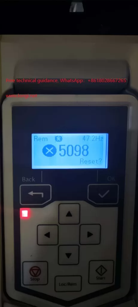
  1. ** Flickering or Blurred Display/Image**:
    • Causes: Low resolution, fast scanning speed, power issues, or loose connections.
    • Solutions: Adjust resolution, slow down scanning speed, check power and connection cables.
  2. Device Failure to Start:
    • Causes: Power control issues, blown fuse, faulty switching power supply.
    • Solutions: Check power control, replace fuse, repair or replace switching power supply.
  3. Filament Failure to Turn On:
    • Causes: Unrecognized high-voltage box, faulty switching power supply.
    • Solutions: Check high-voltage box fiber and power input, repair or replace switching power supply.
  4. Unclear Image:
    • Causes: Incorrect contrast settings, dirty sample surface, autofocus issues.
    • Solutions: Adjust contrast, clean the sample, check and repair autofocus.
  5. Software Conflict or System Incompatibility:
    • Causes: Incompatible operating system or software version conflict.
    • Solutions: Update OS and software, or choose more compatible software.

IV. Precautions

  • Maintain a clean, vibration-free, and electromagnetic interference-free environment.
  • Ensure precise sample preparation.
  • Set parameters reasonably based on sample properties and observation needs.
  • Handle with care, follow operating procedures and safety requirements.

V. Brands and Models of SEMs Repaired by Longi Electromechanical Company

  1. Thermo Fisher Scientific (FEI):
    • Helios G4 UX DualBeam
    • Helios G4 CX DualBeam
    • Apreo 2 SEM
    • (Additional models listed…)
  2. JEOL:
    • JSM-7900F
    • JSM-7800F
    • (Additional models listed…)
  3. Hitachi High-Tech:
    • SU9000
    • SU8700
    • (Additional models listed…)
  4. Carl Zeiss:
    • GeminiSEM 500
    • GeminiSEM 300
    • (Additional models listed…)
  5. Tescan:
    • Mira3
    • Mira4
    • (Additional models listed…)
  6. Phenom-World (Thermo Fisher Scientific):
    • Phenom Pharos
    • Phenom ProX
    • (Additional models listed…)
  7. COXEM:
    • EM-30AX Plus
    • CX-200Plus
    • (Additional models listed…)
  8. Nanoscience Instruments:
    • Apreo S
    • Verios G4
    • (Additional models listed…)
  9. Rigaku:
    • nano3DX
    • XtaLAB Synergy-R
    • (Additional models listed…)
  10. Aspex Corporation:
    • Explorer
    • Personal SEM
    • (Additional models listed…)
  11. Leica Microsystems:
    • EM ACE600
    • EM ACE900
    • (Additional models listed…)
  12. Nikon:
    • Eclipse LV150N
    • Eclipse LV100ND
  13. Bruker:
    • ContourGT
    • Contour Elite
    • JPK NanoWizar

VI. About Longi Electromechanical Company

With nearly 30 years of experience in SEM repair, Longi Electromechanical Company offers quick and efficient repairs for various instruments. Additionally, we recycle and sell used SEMs. Welcome to consult us for more information.


Posted on Leave a comment

Rheometer: Principles, Brand,Usage, Common Faults, and Maintenance

1. Principles of Rheometer

A rheometer is an instrument used to measure the rheological properties of fluids under different conditions. Its measurement principles are based on applying stress or strain to the fluid and measuring the fluid’s response under these conditions. The specific principles include:

  • Rotational Rheometer: By rotating the measuring element (such as a rotor or cone), shear strain is generated in the fluid, and the required torque or resistance is measured to determine the fluid’s viscosity, shear stress, and rheological characteristics.
  • Capillary Rheometer: The fluid flows through a capillary tube, and its viscosity and rheological behavior are studied by measuring the pressure drop and flow rate.
  • Oscillatory Rheometer: Oscillatory strain or stress is applied to the fluid, and the fluid’s elastic modulus, viscous modulus, and damping characteristics are measured.
  • Tensile Rheometer: Tensile strain is applied to the fluid, and its tensile properties are measured.
  • Cone-Plate Rheometer: Using a cone-plate structure, shear strain is generated in the fluid, and the fluid’s viscosity and rheological characteristics are measured.

2. Usage of Rheometer

The usage of a rheometer typically includes the following steps:

Startup Preparation:

  • Turn on the air compressor (air valve closed).
  • Allow air pressure to rise to the standard value (e.g., 5-8 bar).
  • Open the air valve.
  • Turn on the constant temperature water bath (ensure external circulation mode).
  • Turn on the main power supply and confirm the status of the main unit.
  • After self-check, press “ONLINE” to turn off the indicator light and initialize the displacement.
  • Open the rheometer software, press “ONLINE” to turn on the indicator light, and initialize the connection.

Experimental Operation:

  • Install the measuring jig and sample.
  • Set experimental parameters such as temperature, rotation speed, stress, etc.
  • Start the experiment and record data.

Experiment Completion:

  • Remove the measuring jig and clean the jig and cylinder.
  • Turn off the main power supply, water bath, and air compressor.
  • Organize the experimental instruments and equipment.

3. Common Faults and Maintenance Methods

The rheometer may encounter the following common faults during use, and the corresponding maintenance methods are as follows:

  • Sample Not Flowing or Unstable Flow:
    • Cause: Insufficient sample volume, too thick sample, bubbles in the sample, or sample not fully melted.
    • Maintenance Method: Increase sample volume, reduce sample thickness, centrifuge or filter the sample, ensure the sample is fully melted at the test temperature.
  • Poor Repeatability of Test Results:
    • Cause: Unstable sample properties, instrument fault, improper operation, or environmental factors.
    • Maintenance Method: Use a more stable sample, inspect and repair the instrument, recheck the operation process, control environmental factors.
  • Large Deviation in Test Results:
    • Cause: Uneven sample, improper operation, instrument fault, or inaccurate test conditions.
    • Maintenance Method: Use a more uniform sample, recheck the operation process, inspect and repair the instrument, adjust test conditions.
  • Instrument Unable to Start or Automatically Stops:
    • Cause: Power failure, internal instrument fault, safety protection mechanism.
    • Maintenance Method: Check the power plug and power cord, inspect and repair the internal instrument, check the safety protection mechanism and adjust.
  • No Display or Abnormal Display on the Screen:
    • Cause: Internal instrument fault, power failure, connection issue.
    • Maintenance Method: Inspect and repair the internal instrument, check the power plug and power cord, ensure the connection cables are properly inserted.
  • Abnormal Sound or Odor During Testing:
    • Cause: Abnormal sample properties, instrument fault, improper operation.
    • Maintenance Method: Recheck the operation process, inspect and repair the instrument, check the sample properties.
  • Mechanical Fault:
    • Cause: Broken, worn, or stuck transmission system.
    • Maintenance Method: Inspect and replace transmission components, ensure the transmission system is smooth.
  • Electrical Fault:
    • Cause: Power failure, poor wire contact, control circuit fault.
    • Maintenance Method: Check the power supply, wires, and control circuit, perform necessary repairs or replacements.
  • Temperature Control Fault:
    • Cause: Fault in the temperature control system.
    • Maintenance Method: Inspect and repair the temperature control system, ensure accurate temperature control.
  • Sensor Fault:
    • Cause: Damaged or faulty sensor.
    • Maintenance Method: Inspect and replace the sensor, ensure accurate data collection.
  • Software Fault:
    • Cause: Fault in the control software.
    • Maintenance Method: Reinstall or update the software, ensure the software runs normally.

If any issues are encountered during the use of the rheometer, it is recommended to promptly consult professionals or the manufacturer for resolution.

4. Brands and Models of Rheometers Repaired by Longi Electromechanical

  • Anton Paar:
    1. MCR 302
    2. MCR702 MultiDrive
    3. MCR 502 WESP
    4. MCR502
    5. MCR72
    6. MCR 92
  • TA Instruments:
    1. Discovery HR-3
    2. Discovery HR-2
    3. Discovery HR-1
    4. DHR-1
    5. DHR-2
    6. DHR-3
    7. AR-G2
  • Malvern Panalytical:
    1. Kinexus Pro+
    2. Kinexus Ultra+
    3. Kinexus Lab+
    4. Rosand RH2000
    5. Rosand RH7
    6. Rosand RH10
    7. Rosand RH50
  • Brookfield (Ametek Brookfield):
    1. RSX Rheometer
    2. RST Rheometer
    3. DVNext Rheometer
    4. PFT Powder Flow Tester
    5. CT3 Texture Analyzer
  • Thermo Scientific:
    1. HAAKE MARS 60
    2. HAAKE Viscotester iQ
    3. HAAKE RotoVisco 1
    4. HAAKE RheoStress 1
  • Anton Paar Physica:
    1. MCR 302 WESP
    2. MCR 502 TDR
    3. MCR 102
    4. MCR 302 MultiDrive
  • ATS RheoSystems:
    1. RST Controlled Stress Rheometer
    2. Viscoanalyzer, EML Rheometer
  • Rheosense:
    1. m-VROC
    2. e-VROC
    3. microVISC
  • Thermo Fisher Scientific:
    1. HAAKE Viscotester 550
    2. HAAKE MARS iQ, HAAKE Viscotester 3
  • Reologica Instruments:
    1. Stresstech HR
    2. Kinexus DSR-E
    3. Bohlin Gemini 2

Longi Electromechanical has nearly 30 years of experience in repairing rheometers and can quickly repair various types of instruments. Additionally, we recycle and sell various used rheometers. Welcome to consult.

Posted on Leave a comment

Trace Oxygen Analyzer: Principles, Brands & Models, Usage, and Troubleshooting Guide

I. Classification of Trace Oxygen Analyzer Principles

Trace oxygen analyzers are crucial tools for detecting minute amounts of oxygen in the environment. Their principles are mainly categorized into fuel cell and zirconia methods.

1. Fuel Cell Trace Oxygen Analyzer

  • Principle: Utilizes a fully sealed fuel cell oxygen sensor consisting of highly active oxygen and lead electrodes immersed in a KOH solution. Oxygen molecules in the sample gas diffuse through a polymer membrane to the oxygen electrode, where they undergo an electrochemical reaction. The generated current is proportional to the oxygen content in the sample gas.
  • Advantages: Maintenance-free, stable and reliable sensor, no need for regular cleaning or replacement.

2. Zirconia Trace Oxygen Analyzer

  • Principle: Employs a zirconia element as the key component of the oxygen detection cell. At high temperatures, oxygen diffuses from the side with higher partial pressure to the side with lower partial pressure, creating a potential difference, which is used to measure oxygen content.
  • Advantages: Wide measurement range, easy to use, long service life.

II. Usage Instructions

  1. Instrument Startup: Ensure the portable trace oxygen analyzer is in normal working condition.
  2. Mobile Detection: Hold the antioxidant and corrosion-resistant detection rod to measure the concentration of trace oxygen gas in the environment.
  3. Data Recording: Utilize the instrument’s storage and memory function to record data per second during detection, facilitating subsequent query and computer printing.

III. Common Faults and Troubleshooting Methods

  1. No Response to Sample Gas
    • Cause: Sensor failure.
    • Repair Method: Check instrument connections for normality or replace the sensor.
  2. No Display on Instrument
    • Cause: Fuse burnout or circuit failure.
    • Repair Method: Replace the fuse or send to a professional repair center.
  3. Slow Response or Poor Linearity
    • Cause: Sensor aging, presence of liquids or dust, gas path leakage.
    • Repair Method: Replace the sensor, clean the pipelines, or repair the leakage.
  4. No Indication on Flowmeter
    • Cause: Filter at the inlet is blocked or internal pipelines are clogged.
    • Repair Method: Check the filter screen or send the instrument back to the manufacturer for repair.
  5. High or Low Indication
    • Cause: Signal drift, presence of other interfering gases, inaccurate sensor calibration, gas path leakage.
    • Repair Method: Recalibrate the instrument, filter out other interfering gases, check and repair gas path leakage, replace the sensor.
  6. Garbled Display
    • Cause: Strong external power interference or instrument detection program issues.
    • Repair Method: Add a purified power supply stabilizer or send the instrument to a professional repair center.
  7. Internal Instrument Fault
    • Cause: Associated with fault codes.
    • Repair Method: Refer to the fault code instructions in the instrument manual for targeted troubleshooting.
  8. Power Issues
    • Cause: Poor power cord connection or faulty power socket.
    • Repair Method: Check power cord connection and power socket, and conduct professional repair if necessary.
  9. Ambient Temperature Changes
    • Cause: Large ambient temperature changes, sensor aging or contamination.
    • Repair Method: Avoid using the instrument in environments with large temperature changes, regularly replace or clean the sensor.

IV. Longi Ectromechanical Company Repair Services

Longi Ectromechanical Company, with nearly 30 years of experience in trace oxygen analyzer repair, can quickly repair various types of instruments. The company also offers services for recycling and selling various used analyzers. Below are some of the brands and models that have been repaired:

  • Process Insights: MTO2-2000, ZIRCOMAT, OXYMAT 6
  • ADEV: G1501, OXY ONE, OXY CHECK, OXY MANAGER
  • Pittcon Instruments: POA200, 209 Series, Model 211, Model 212
  • In-Situ: EN-500, RDO PRO-X, Aqua TROLL 600, TROLL 9500
  • Servomex: SERVOPRO MultiExact 4100, SERVOPRO MonoExact DF310E, SERVOPRO 4900 Multigas, SERVOPRO NanoChrome
  • Teledyne Analytical Instruments: 3000TA, 3000T Series, 3000MB Series, 3000MA
  • AMETEK: 2000H, 3000TA, 3000MA, ta7000
  • Michell Instruments: XZR400, XZR500, XTP601, XZR200
  • Systech Illinois: EC900, EC923, EC91, EC92DIS
  • Mettler-Toledo: Thornton 499AO, 5900 Series, 5500 Series, 4900 Series
  • Yokogawa: ZR22, ZR202, ZR402, AV550G
  • Delta F Corporation: DF-150E, DF-500, DF-560E, DF-745
  • Analytical Industries Inc. (AII): GPR-1500, GPR-2500, GPR-3100, GPR-4100
  • GE Analytical Instruments: Oxy.IQ, Oxy.IQ II

For trace oxygen analyzer repair services, please contact Longi Ectromechanical Company.

Posted on Leave a comment

ACS530 VFD 5098 Alarm Fault Analysis and Troubleshooting

ACS530 VFD 5098 Alarm Fault Analysis and Troubleshooting

When working with ABB’s ACS530 series VFDs (Variable Frequency Drives), encountering specific fault alarms such as the 5098 alarm can be a concern. While the ACS530 series manual may not directly mention this alarm code, by referencing the manual of its similar ACS580 series VFDs, also from ABB, we can gain insight into the 5098 alarm and apply that knowledge to troubleshooting the ACS530 series.

Physical picture of ACS530 with fault number 5098

I. Understanding the 5098 Alarm

In the ACS580 series, the 5098 alarm indicates “I/O Communication Lost,” signifying a failure in communication with the standard I/O (Input/Output) devices. This usually occurs when there is an issue with the communication link between the VFD’s I/O terminal board (where analog inputs like AI1 reside) and the main board. Similarly, in the ACS530 series, the 5098 alarm likely indicates a communication issue as well.

II. Possible Causes of the Fault

  1. Power Issues:
    • The 10V or 24V power supply on the I/O terminal board may be abnormal, leading to unstable or failed communication.
    • There may be short circuits, open circuits, or poor connections in the power lines.
  2. Hardware Connection Problems:
    • Connections between the I/O terminal board and the main board may be loose, have cold solder joints, or be corroded.
    • Terminals may have aged due to prolonged use, resulting in poor contact.
  3. Communication Module Failure:
    • The VFD’s I/O communication module may be damaged, preventing proper communication with the I/O terminal board.
  4. Software or Configuration Issues:
    • The VFD’s software configuration may have errors, affecting communication protocols or parameter settings.
    • Despite similarities in design and software between the ACS530 and ACS580 series, subtle differences in configuration may lead to unexpected alarms in the ACS530 under certain conditions.
Physical picture of ABB inverter ACS530

III. Fault Troubleshooting Steps

To address the 5098 alarm in the ACS530 VFD, follow these troubleshooting steps:

  1. Check Power Supplies:
    • Use a multimeter to verify the 10V and 24V power supplies on the I/O terminal board are functioning correctly.
    • Inspect power lines for completeness, shorts, or open circuits.
  2. Inspect Hardware Connections:
    • Disconnect all connections related to the I/O terminal board, reconnect them securely, and ensure they are tight.
    • Examine the connections between the I/O terminal board and the main board for looseness, cold solder joints, or corrosion, and make necessary repairs.
  3. Assess Communication Module:
    • If possible, test replacing the I/O communication module with an identical one to determine if it’s faulty.
  4. Reset and Restart:
    • Attempt to reset the VFD to clear the alarm.
    • If resetting fails, power off the VFD, wait for a while, and then power it back on to eliminate any software-related communication issues.
  5. Contact Technical Support:
    • If none of the above steps resolve the issue, contact ABB’s technical support team or a professional service provider for further diagnosis and repair.

IV. Conclusion

Despite the ACS530 series VFD manual’s lack of direct mention of the 5098 alarm, referencing similar ACS580 series documentation and contextual analysis enables understanding the likely fault type and appropriate troubleshooting methods. In practice, consider all potential causes

Posted on Leave a comment

Working Principle, Operation, and Maintenance of Dispensing Machines

Working Principle and Operation of Dispensing Machines

Working Principle:
Dispensing machines primarily utilize compressed air or pressure systems to transfer adhesive from the reservoir to the dispensing nozzle, with precise control of adhesive flow rate and direction achieved through control valves. During operation, the machine applies adhesive accurately onto workpieces at predetermined positions and shapes, based on preset parameters such as adhesive flow rate, speed, duration, and the machine’s movement path.


I. Usage of Dispensing Machines

  1. Preparing Adhesive:
    • Inject adhesive into the reservoir and secure it onto the machine.
  2. Setting Parameters:
    • Configure the machine’s working parameters, including adhesive flow rate, speed, and duration, as required.
  3. Placing Workpieces:
    • Position the workpiece requiring adhesive on the machine’s workbench and secure it in place.
  4. Starting Up and Setting:
    • Turn on the dispensing machine’s power switch and, following the instructions on the operation panel or touchscreen, set the dispensing position and shape for the workpiece.
  5. Checking and Starting:
    • Verify that the adhesive flow rate and workbench movement speed meet requirements, then start dispensing to ensure uniform application of adhesive on the workpiece.
  6. Ending and Cleaning:
    • After dispensing, turn off the machine’s power switch and clean the machine, dispensing nozzle, and other components to prevent adhesive from drying and causing blockages.

II. Common Faults and Repair Methods

  1. Nozzle Blockage:
    • Cause: Incomplete cleaning of the adhesive valve or needle, impurities in the adhesive, or mixing of incompatible adhesives.
    • Solution: Replace with a clean needle, use higher-quality adhesive, and clean the adhesive valve promptly.
  2. Adhesive Valve Dripping or Leakage:
    • Cause: Needle diameter too small, affecting bubble venting, leading to backpressure and post-dispensing dripping.
    • Solution: Replace with a larger needle, add a suction function, use less bubble-prone adhesive, and perform de-bubbling before use.
  3. Slow Flow Rate:
    • Cause: Excessively long liquid transfer tubing causing unstable air pressure loss.
    • Solution: Shorten tubing length, adjust dispensing outlet and air pressure to increase flow rate.
  4. Bubbles in Fluid:
    • Cause: Excessive feed pressure and short valve-opening time, introducing air into the liquid.
    • Solution: Reduce feed fluid pressure and use a conical luer needle.
  5. Inconsistent Dispensing Size:
    • Cause: Unstable pressure pump or feed pressure.
    • Solution: Ensure control pressure of the adhesive valve reaches at least 60 psi and avoid using the low-pressure section of the pressure gauge.
  6. Stringing or Tailing:
    • Cause: Inadequate adjustment of process parameters, such as small needle inner diameter, high dispensing pressure, or large distance between needle and PCB.
    • Solution: Adjust process parameters, replace with a needle with a larger inner diameter, reduce dispensing pressure, adjust needle height from PCB, or heat the dispensing needle to lower viscosity.
  7. Satellite Dots:
    • Cause: Tailing and needle disconnection or incorrect jet height during non-contact jetting.
    • Solution: Check for needle damage, adjust equipment parameters to prevent tailing, and adjust jet head height from PCB.
  8. Popcorn or Voids:
    • Cause: Air or moist gas entering the adhesive.
    • Solution: Use low temperature for slow curing, extend heating time, shorten the time between placement and curing, and perform de-bubbling for self-filled adhesives.
  9. Empty Dispensing or Insufficient Adhesive Output:
    • Cause: Bubbles in the adhesive, needle blockage, or insufficient air pressure.
    • Solution: Perform de-bubbling on the adhesive in the syringe, replace with a clean needle, and appropriately adjust machine pressure.
  10. Intermittent Adhesive Dots:
    • Cause: Needle plunger landing on the soldering pad.
    • Solution: Replace with a different needle, increase delay, or adjust the ratio of pressure to cycle time.
  11. Component Displacement:
    • Cause: Uneven adhesive dots, inappropriate placement height, or excessive adhesive.
    • Solution: Adjust the placement machine’s working status, replace the adhesive, and specify PCB placement time in the process documentation.
  12. Component Falling Off After Curing or Wave Soldering:
    • Cause: Low curing temperature, insufficient adhesive, or contaminated components/PCB.
    • Solution: Retest the PCB’s curing curve, adjust curing temperature, and inspect components or PCB for contamination.

III. Brands and Models of Dispensing Machines Repaired by Longi Ectromechanical Company

  1. Nordson EFD:
    • Ultimus V
    • Performus X100
    • 794 Series
    • 736HPA
    • Liquidyn P-Dot CT
  2. Musashi Engineering:
    • Shotmaster 300DS
    • SuperΣ CMII
    • Image Master 350PC Smart
    • Smart Dispenser 300
  3. Asymtek (Nordson Asymtek):
    • Spectrum S-820
    • Quantum Q-6800
    • ACJ-3 Controller
    • DispenseMate D-583
    • Helios SD-960
  4. Fisnar:
    • CV629
    • F1300N
    • F4200N
    • DC100
    • I&J123-D
  5. Techcon Systems:
    • TS5000DMP
    • TS8100 Series
    • TS9000 Jet Tech
    • TS5540
  6. GPD Global:
    • MAX Series
    • Island Series
    • PCD Series
    • NCM5000
  7. VERMES Microdispensing:
    • MDS 3010+
    • MDS 3200A
    • MDS 3250+
  8. Camalot (ITW EAE):
    • Prodigy
    • XyflexPro+
    • FX-D
  9. PVA (Precision Valve & Automation):
    • Delta 6
    • Delta 8
    • Sigma
    • FCS300
  10. Valco Melton:
    • FlexSpray
    • D4 Series
    • 524 System

Longi Ectromechanical Company specializes in the long-term maintenance of dispensing machines, with nearly 30 years of experience in quick repairs for various instruments. We also buy and sell used dispensing machines. For inquiries, please contact us.

Posted on Leave a comment

 Understanding and Using a Colorimeter: Principles, Instructions, Faults, and Brands

Colorimeter: An Optical Measurement Instrument Simulating Human Eye’s Response to Red, Green, and Blue Light

I. Working Principle of Colorimeter

Optical System:

  • The colorimeter typically consists of a light source, a sample, and a detector (or sensor).
  • The light source emits light (which can be white light or specific wavelengths, such as the D65 light source simulating natural lighting conditions), and the light passes through or reflects off the sample before being received by the detector.

Color Detection:

  • The detector usually has three channels corresponding to red, green, and blue.
  • Each detector is calibrated to respond to specific wavelengths associated with its respective color channel.
  • The detected light intensities are used to calculate the object’s tristimulus values (X, Y, Z), representing the object’s color in a standardized color space (e.g., CIE XYZ color space).

Color Space:

  • The colorimeter can convert between different color spaces (e.g., RGB, Lab, LCH, etc.).
  • The Lab color space is one of the commonly used spaces, consisting of lightness (L), the a-axis (red-green axis), and the b-axis (yellow-blue axis).

Color Difference Calculation:

  • The colorimeter assesses color consistency by measuring the difference between the sample and a standard sample.
  • It first measures the color information of the standard sample as a reference, then measures the color information of the test sample, and compares the two.
  • The color difference value is calculated using mathematical algorithms (such as ΔE*ab) to evaluate the degree of color difference in the sample.

II. Usage Instructions for Colorimeter

  1. Warm-up:
    • Turn on the colorimeter and allow it to warm up for a specified time (e.g., 30 minutes) to ensure stable performance.
  2. Calibration:
    • Calibrate the instrument according to the manual before measurements to ensure accuracy.
    • Calibration typically includes zero calibration and white calibration steps.
  3. Select Color Parameters:
    • Choose the appropriate color parameters (e.g., CIE Lab*, CIE LCh) based on measurement needs.
  4. Place the Sample:
    • Position the test sample on the measurement platform, ensuring it is flat, without reflection or impurities.
    • For opaque samples, place them on a black background for measurement.
  5. Set Measurement Mode:
    • Choose the suitable measurement mode (e.g., standard mode, quick mode) based on actual requirements and set parameters such as light source and observation angle.
  6. Start Measurement:
    • Follow the manual’s instructions to set the measurement mode and press the start button. The instrument will measure automatically.
  7. Record Data:
    • After measurement, the instrument will display the results. Record relevant data (e.g., L, a, b* values) as needed for further analysis.
  8. Clean the Instrument:
    • Clean the instrument’s surface and internal parts promptly after use to maintain cleanliness.
  9. Shutdown and Storage:
    • Turn off the instrument after all measurements. Store it in a dry, cool place, avoiding direct sunlight and humid environments.

III. Common Faults and Repair Methods

1. Light Source Issues:

  • Fault Manifestation: Damaged light source, failure to illuminate, or insufficient brightness.
  • Possible Causes: Damaged light source, poor line connection, insufficient battery power, or damaged battery.
  • Repair Methods:
    • Check and replace the light source (e.g., pulsed xenon lamp or tungsten bulb).
    • Check line connections for proper contact.
    • Replace or recharge the battery.

2. Battery Issues:

  • Fault Manifestation: Insufficient battery power, failure to charge, or damaged battery causing instrument malfunction.
  • Possible Causes: Aging battery, incorrect battery installation, poor battery contact.
  • Repair Methods:
    • Install the battery correctly.
    • Check battery power and recharge or replace as needed.

3. Display Issues:

  • Fault Manifestation: LCD screen failure or abnormal display.
  • Possible Causes: No battery installed, insufficient battery power, incorrect battery installation, line fault.
  • Repair Methods:
    • Install the battery or connect the AC adapter correctly.
    • Check and repair line faults.

4. Key Malfunctions:

  • Fault Manifestation: Measurement buttons or body keys not functioning.
  • Possible Causes: Damaged keys, charging in progress, or connection to a PC application.
  • Repair Methods:
    • Ensure to press the measurement button when the READY indicator is on after charging.
    • Disconnect from the PC application.
    • Replace damaged keys or have them repaired by professionals.

5. Connection Issues:

  • Fault Manifestation: Failure to connect to PC applications or printers.
  • Possible Causes: Incorrect connection method, multiple instruments connected in the PC.
  • Repair Methods:
    • Connect to the PC correctly, ensuring only one instrument is connected.
    • Select the correct connection option from the settings screen (e.g., “USB Connection” → “PC” or “Printer”).

6. Indicator and Buzzer Issues:

  • Fault Manifestation: LED indicator not lighting up, buzzer not sounding.
  • Possible Causes: Settings issue (e.g., set to “off”).
  • Repair Methods:
    • Connect to the PC application and check/modify relevant settings.

7. Calibration Issues:

  • Fault Manifestation: Colorimeter unable to complete calibration or inaccurate calibration results.
  • Possible Causes: Worn, contaminated, or discolored calibration white board, or incorrect execution of the calibration process.
  • Repair Methods:
    • Clean or replace the calibration white board.
    • Follow the manual to execute the calibration process correctly.

8. System Faults:

  • Fault Manifestation: General system errors, instrument malfunction.
  • Possible Causes: Aging bulb, aging circuit board, software issues.
  • Repair Methods:
    • Replace the bulb or circuit board.
    • Upgrade or restore software to the latest version.
    • For complex issues, contact Longi Ectromechanical Company or a professional repair team for inspection and repair.

IV. Brands and Models of Colorimeters Repaired by Longi Ectromechanical Company

  1. Datacolor:
    • Datacolor 600
    • Check 3
    • SpyderX Elite
    • ColorReader Pro
    • SpectraVision Spectro 700
    • SpectraVision Spectro 1000
  2. Konica Minolta:
    • CM-700d
    • CM-600d
    • CM-5
    • CM-3600A
    • CM-3610A
    • CM-25d
    • CM-26dG
  3. X-Rite:
    • Ci64
    • Ci7600
    • Ci7800
    • eXact Standard
    • eXact Advanced
    • RM200QC
  4. HunterLab:
    • UltraScan PRO
    • ColorFlex EZ
    • LabScan XE
    • MiniScan EZ 4500L
    • Vista
  5. BYK-Gardner:
    • spectro2guide
    • spectro-guide
    • micro-gloss
    • color-guide
  6. 3NH (ThreeNH):
    • YS6060
    • NH310
    • TS7600
    • NS800
    • NH300
  7. PCE Instruments:
    • PCE-CSM 8
    • PCE-CSM 10
    • PCE-CSM 20
    • PCE-TCD 100
  8. Hach:
    • DR1900
    • DR6000

Longi Ectromechanical Company has nearly 30 years of experience in repairing colorimeters, enabling swift repairs for various instruments. Additionally, we recycle and sell used colorimeters. For more information, please feel free to contact us.

Posted on Leave a comment

Introduction to Colorimeter: Working Principle, Usage, Faults, and Repair by Longi Ectromechanical Company

Colorimeter: An Optical Instrument for Color Measurement

1. Introduction to Colorimeter

A colorimeter is an optical measurement instrument that simulates the human eye’s response to red, green, and blue light. It assesses color differences by measuring the intensity of light reflected or transmitted from the surface of an object, based on the concept of color space.

2. Working Principle of Colorimeter

Optical System:

  • The colorimeter typically consists of a light source, sample, and detector (or sensor).
  • The light source emits light (which can be white light or specific wavelengths, such as the D65 light source, used to simulate natural lighting conditions). The light passes through the sample and is then received by the detector.

Color Detection:

  • The detector usually has three channels corresponding to red, green, and blue.
  • Each detector is calibrated to respond to specific wavelengths of light associated with its respective color channel.
  • The detected light intensity is used to calculate the object’s tristimulus values (X, Y, Z), representing its color in a standardized color space (such as the CIE XYZ color space).

Color Space:

  • The colorimeter can convert between different color spaces (such as RGB, Lab, LCH, etc.).
  • The Lab color space is one of the commonly used color spaces, consisting of lightness (L), the a-axis (red-green axis), and the b-axis (yellow-blue axis).

Color Difference Calculation:

  • The colorimeter assesses color consistency by measuring the color difference between the sample and a standard sample.
  • It first measures the color information of the standard sample as a reference, then measures the color information of the sample to be tested, and compares the two.
  • The color difference value between the two is calculated using mathematical algorithms (such as ΔE*ab) to evaluate the degree of color difference in the sample.

3. Usage Instructions for Colorimeter

  1. Warm-up: Turn on the colorimeter power and preheat for a certain period (such as 30 minutes) to ensure stable instrument performance.
  2. Calibration: Calibrate the instrument according to the instructions before measurement, including zero calibration and white board calibration.
  3. Select Color Parameters: Choose the appropriate color parameters (such as CIE Lab*, CIE LCh, etc.) based on measurement needs.
  4. Place Sample: Place the sample on the measuring platform, ensuring it is flat, without reflection or impurities. For opaque samples, measure on a black background.
  5. Set Measurement Mode: Choose the appropriate measurement mode (such as standard mode, quick mode, etc.) based on actual needs, and set parameters such as light source and observation angle.
  6. Start Measurement: Follow the instrument instructions to set the measurement mode and press the start button. The instrument will measure automatically.
  7. Record Data: After measurement, the instrument will display the results. Record relevant data (such as L, a, b* values, etc.) as needed for further analysis.
  8. Clean Instrument: Clean the instrument surface and internal parts after measurement to maintain cleanliness.
  9. Shutdown and Storage: Turn off the instrument power after all measurements. Store the instrument in a dry, cool place, avoiding direct sunlight and humid environments.

Additional Precautions:

  • Keep the instrument stable, avoiding severe vibration or collision.
  • Regularly inspect and replace easily damaged parts such as light sources and detectors.
  • Follow the operation and maintenance requirements in the instrument instructions.

4. Common Faults and Repair Methods

Light Source Issues:

  • Fault: Light source damage, failure to illuminate, or insufficient brightness.
  • Possible Causes: Damaged light source, poor line connection, insufficient battery power, or damaged battery.
  • Repair Methods: Check and replace the light source (such as a pulsed xenon lamp or tungsten bulb), check line connections for good contact, replace or recharge the battery.

Battery Issues:

  • Fault: Insufficient battery power, failure to charge, or instrument malfunction due to damaged battery.
  • Possible Causes: Battery aging, incorrect battery installation, or poor battery contact.
  • Repair Methods: Install the battery correctly, check battery power and recharge or replace as needed.

Display Issues:

  • Fault: LCD screen failure or abnormal display.
  • Possible Causes: No battery installed, insufficient battery power, incorrect battery installation, or line fault.
  • Repair Methods: Install the battery or connect the AC adapter correctly, check and repair line faults.

Button Malfunction:

  • Fault: Measurement buttons or body buttons do not function.
  • Possible Causes: Damaged buttons, charging in progress, or connection to a PC application.
  • Repair Methods: Press the measurement button after charging is complete and the READY indicator is on. Disconnect from the PC application if connected. If the button is damaged, replace it or have it repaired by professionals.

Connection Issues:

  • Fault: Unable to connect to PC applications or printers.
  • Possible Causes: Incorrect connection method, multiple instruments connected in the PC.
  • Repair Methods: Connect to the PC end correctly, ensuring only one instrument is connected. Select the correct connection option from the settings screen (such as “USB Connection” → “PC” or “Printer”).

Indicator and Buzzer Issues:

  • Fault: LED indicator does not light up, buzzer does not sound.
  • Possible Causes: Settings issue (such as being set to “off”).
  • Repair Methods: Connect to the PC application and check or modify relevant settings.

Calibration Issues:

  • Fault: The colorimeter cannot complete calibration or the calibration result is inaccurate.
  • Possible Causes: Worn, contaminated, or discolored calibration white board, or incorrect execution of the calibration process.
  • Repair Methods: Clean or replace the calibration white board. Perform the calibration process correctly according to the instructions.

System Faults:

  • Fault: Conventional system errors, instrument malfunction.
  • Possible Causes: Aged bulb, aged circuit board, or software issues.
  • Repair Methods: Replace the bulb or circuit board. Upgrade or restore software to the latest version. For complex issues or those that cannot be resolved independently, contact Longi Ectromechanical Company’s professional repair team for detection and repair.

5. Brands and Models of Colorimeters Repaired by Longi Ectromechanical Company

Datacolor:

  1. Datacolor 600
  2. Check 3
  3. SpyderX Elite
  4. ColorReader Pro
  5. SpectraVision Spectro 700
  6. SpectraVision Spectro 1000

Konica Minolta:

  1. CM-700d
  2. CM-600d
  3. CM-5
  4. CM-3600A
  5. CM-3610A
  6. CM-25d
  7. CM-26dG

X-Rite:

  1. Ci64
  2. Ci7600
  3. Ci7800
  4. eXact Standard
  5. eXact Advanced
  6. RM200QC

HunterLab:

  1. UltraScan PRO
  2. ColorFlex EZ
  3. LabScan XE
  4. MiniScan EZ 4500L
  5. Vista

BYK-Gardner:

  1. spectro2guide
  2. spectro-guide
  3. micro-gloss
  4. color-guide

3NH (ThreeNH):

  1. YS6060
  2. NH310
  3. TS7600
  4. NS800
  5. NH300

PCE Instruments:

  1. PCE-CSM 8
  2. PCE-CSM 10
  3. PCE-CSM 20
  4. PCE-TCD 100

Hach:

  1. DR1900
  2. DR6000

6. Conclusion

Longi Ectromechanical Company specializes in the repair of colorimeters, with nearly 30 years of experience. We can quickly repair various types of instruments and also offer recycling and sales of used colorimeters. For more information, please contact us.

Posted on Leave a comment

Potentiometric Analyzers: Common Faults, Maintenance, and Specifications

Potentiometric Analyzers (e.g., Zeta Potential Analyzers) in Laboratory and Industrial Applications: Common Faults and Maintenance

I. Common Faults and Repair Methods

  1. No Power, Power Indicator Not Lit
    • Fault Causes:
      • Main power circuit breaker tripped.
      • Power fuse blown.
      • Indicator light damaged.
    • Repair Methods:
      • Check for short circuits in the device and reset the circuit breaker.
      • Replace the fuse or indicator light.
  2. Abnormal Output Voltage and Current, C1 Potential Indicator Drops
    • Fault Causes:
      • Insulating flange short-circuited.
      • Short-circuited with other underground metal structures.
      • Reference electrode damaged.
    • Repair Methods:
      • Repair the short-circuited insulating flange and disconnect from underground metal structures.
      • Check the reference electrode measurement wire or replace the reference electrode.
  3. Increased Noise
    • Fault Causes:
      • Uneven placement of the case.
      • Poor contact of the main relay.
      • Loose bolts on the main transformer or filter reactor.
    • Repair Methods:
      • Level the case.
      • Replace the main relay.
      • Tighten loose bolts.
  4. Fault Light On
    • Fault Causes:
      • Test conversion jump.
      • Open circuit in anode or cathode bus cable.
      • Open circuit or failure in reference electrode cable.
    • Repair Methods:
      • Press the reset button.
      • Check the anode or cathode bus cable.
      • Check the reference electrode cable or replace the reference electrode.
  5. Open Circuit in Cathode Line
    • Diagnosis:
      • Use a ZC-8 ground resistance tester to measure the grounding resistance of the anode cable. After confirming the normality of the anode cable, use a multimeter to test the continuity between the output cathode and the zero-position grounding cable to determine if there is an open circuit.
    • Repair Method:
      • Replace the open-circuited output cathode cable.
  6. Open Circuit in Reference Line or Zero-Position Grounding Line
    • Diagnosis:
      • Disconnect and measure the potential using a long-lasting reference electrode placed directly above it, or test the resistance value between these two lines to determine their integrity.
    • Repair Method:
      • Replace the open-circuited cable or reference electrode.
  7. Damaged Reference Electrode or Empty Cupric Sulfate Solution
    • Diagnosis:
      • Use a calibrated standard reference electrode placed as close as possible to the long-lasting reference electrode and use a multimeter to test the potential difference to determine if it falls within the acceptable range.
    • Repair Method:
      • Replace the long-lasting reference electrode or replenish the cupric sulfate solution.

II. Daily Maintenance Considerations

  • Regular Calibration: If performing acid-base titration to determine the isoelectric point or pH value, calibrate the pH probe before each experiment. If testing solution conductivity, calibrate the conductivity probe. The main probe can be calibrated weekly.
  • Cleaning: Clean the main probe, pH probe, and container after each sample change, and dry them to avoid residue affecting experimental results. Thoroughly clean and properly store them after experiments.

III. Potentiometric Analyzers Repaired by Longi Ectromechanical Company and Their Specifications

  1. Metrohm (Switzerland)
    • 905 Titrando: High-precision potentiometric titrator suitable for various complex samples with automation and modular design for laboratory and industrial applications.
    • 888 Titrando: Multi-functional potentiometric titrator supporting multiple titration methods with high precision and reliability for a wide range of applications.
  2. Mettler-Toledo
    • T50: Multi-functional titration system with high precision and user-friendly interface for routine laboratory analysis and research applications.
    • T90: High-end potentiometric titrator offering flexible automation options and advanced data management features for complex and high-demand analysis tasks.
  3. Thermo Fisher Scientific
    • Orion Star T940: High-performance potentiometric titrator with intuitive user interface and multiple titration modes for various electrochemical analyses.
    • Orion Versa Star Pro: Potentiometric titrator providing high-precision potential measurements and multiple titration functions for research and quality control.
  4. Hanna Instruments
    • HI902C: Fully automatic potentiometric titrator with high precision and multi-functionality for a wide range of applications, including food, beverage, and chemical analysis.
  5. Hach
    • AT1000: Fully automatic potentiometric titrator designed for high-precision titration analysis, suitable for water quality analysis and other industrial applications.
  6. SCHOTT Instruments
    • TitroLine 7800: High-end potentiometric titrator with automation and high-precision titration functions for complex analysis tasks in the pharmaceutical, chemical, and food industries.
  7. Malvern Panalytical
    • Zetasizer Nano ZS: High-performance Zeta potential and particle size analyzer for the characterization of nanoparticles, colloids, and proteins with high sensitivity and multi-functionality.
    • Zetasizer Ultra: Provides higher resolution and accuracy for measuring particle size, Zeta potential, and molecular weight, suitable for complex sample analysis.
  8. Anton Paar
    • Litesizer 500: Multi-functional analyzer for measuring particle size, Zeta potential, and molecular weight with high precision and easy-to-use interface for various applications.
  9. Brookhaven Instruments
    • ZetaPALS: High-sensitivity Zeta potential analyzer suitable for sample measurements in low-concentration and high-salt environments, widely used in research and industrial fields.
    • NanoBrook Omni: Comprehensive particle size and Zeta potential analyzer with high precision and reliability for the characterization of various nanomaterials and colloids.
  10. Beckman Coulter
    • DelsaMax PRO: Fast and high-precision Zeta potential analyzer capable of simultaneously measuring particle size and Zeta potential, suitable for high-throughput research and industrial applications.
  11. Horiba
    • SZ-100: Multi-functional nanoparticle size and Zeta potential analyzer with high sensitivity and ease of operation, suitable for research in materials science and life sciences.
  12. Particle Metrix
    • Stabino: Automated Zeta potential analyzer for quick and precise measurement of Zeta potential, suitable for the characterization of colloids and nanomaterials.

Longi Ectromechanical Company has nearly 30 years of experience in repairing potentiometric analyzers and can quickly repair various instruments. Additionally, we recycle and sell used potentiometric analyzers. Please feel free to contact us for more information.

Posted on Leave a comment

Comprehensive Guide to Particle Size Analyzer Faults, Repairs, and Preventive Measures

Particle Size Analyzer (Also known as: Particle Size Tester, Automatic Laser Particle Size Tester, Laser Particle Size Analyzer, Laser Particle Size Tester, Nano Image Particle Size Analyzer, Mean Particle Size Determinator, Particle Size Determinator, Spray Particle Size Tester, Particle Diameter Analyzer)

I. Common Fault Conditions and Troubleshooting

1. Instrument Running Unstably or Stopping:

  • Possible Cause: Power supply issues or internal component damage.
  • Solution: Check for stable power supply connection and inspect internal components for damage.

2. Laser Not Working or Unstable Light Intensity:

  • Possible Cause: Laser source malfunction or improper adjustment.
  • Solution: Check power connection and adjust potentiometer of the laser source; clean the laser surface.

3. Unable to Start or Connect to Computer:

  • Possible Cause: Power cord not properly plugged in or driver/software issues.
  • Solution: Check power cord, reinstall drivers or software, and ensure connection lines are normal.

4. Inaccurate or Deviated Measurement Results:

  • Possible Cause: Improper sample handling or incorrect instrument parameter settings.
  • Solution: Ensure uniform sample distribution and check/adjust instrument parameters such as laser power and scattering angle.

5. Slow Measurement Speed:

  • Possible Cause: High sample concentration or unclean internal optical path.
  • Solution: Select appropriate sample concentration and regularly clean the optical path.

6. Display Screen Abnormality or Error:

  • Possible Cause: Display screen malfunction or system error.
  • Solution: Attempt to restart the instrument or perform a system reset; refer to the user manual or contact technical support.

7. Abnormal Measurement Due to Improper Sample Handling:

  • Possible Cause: Uneven sample distribution, insufficient settlement, or blockage of sample inlet/outlet.
  • Solution: Adequately stir or shake the sample; check and clean the sample inlet and outlet.

8. Data Processing Software Error:

  • Possible Cause: Software incompatibility with the instrument or incorrect settings.
  • Solution: Reinstall or update the software; check settings of the data processing software and calculation formulas.

II. Repair Methods

1. Power Supply Issues:

  • Check if the power cord is tightly plugged in; check for stable power supply voltage, and replace the power socket or use a voltage stabilizer if necessary.

2. Sample Issues:

  • Ensure the sample meets instrument requirements; adequately stir the sample to ensure uniformity; filter to remove impurities.

3. Optical Component Contamination:

  • Use dedicated cleaning agents and tools to clean optical components; handle with care to avoid scratches.

4. Mechanical Component Failures:

  • Check for loose or damaged mechanical components; promptly replace or repair relevant components; ensure safe operation.

5. Software Failures:

  • Attempt to restart the instrument; if the problem persists, contact the manufacturer or professional repair personnel for software updates or repairs.

III. Preventive Measures

  • Regular Cleaning and Maintenance: Keep the instrument surface and interior clean of impurities; regularly clean the optical path.
  • Sample Pretreatment: Ensure a dust-free sample handling process; avoid sample clumping or aggregation.
  • Software Updates: Regularly update the instrument software version to ensure stability and compatibility.
  • Environmental Control: Maintain a stable instrument working environment; avoid influences of temperature, humidity, and other factors on measurement results.

By adopting these measures, the occurrence of faults in particle size analyzers can be effectively reduced, and their measurement accuracy and stability can be improved. For unresolvable faults, it is recommended to promptly contact the professional repair personnel of Longi Ectromechanical Company for assistance.

IV. Brands and Models of Particle Size Analyzers Repaired by Longi Ectromechanical Company

Malvern Panalytical

  • (1) Mastersizer 3000: A laser diffraction particle size analyzer with high precision and rapid measurement capabilities, suitable for various sample types, including wet and dry samples.

Beckman Coulter

  • (1) LS13320: Covers a wide range of particle sizes and efficiently analyzes the particle size distribution of various materials, suitable for research and industrial applications.

Horiba

  • (1) LA-960: Features high resolution and sensitivity, suitable for measuring particles from nanometer to millimeter scale, widely used in chemical, pharmaceutical, and materials science fields.

Sympatec

  • (1) HELOS: Provides high-resolution and precise particle size measurements, suitable for various industrial applications, especially in the pharmaceutical and food industries.

Microtrac

  • (1) Bluewave: Adopts triple laser technology, providing extensive particle size distribution measurements from nanometer to millimeter scale, suitable for research and development as well as quality control.

Anton Paar

  • (1) PSA Series (PSA 1190, PSA 1090): Utilizes laser diffraction technology, offering high precision and reproducibility in particle size measurements, suitable for various industrial and academic research applications.

Cilas

  • (1) Cilas 1190: Adopts advanced optical design, capable of accurately measuring a wide range of particle size distributions, suitable for materials science, pharmaceuticals, and chemicals.

OMEC (OuMeiKe)

  • (1) LS-POP6
  • (2) LS-609
  • (3) LS-609M
  • (4) LS-609Q
  • (5) LS900
  • (6) Easysizer20
  • (7) PAMS 2000
  • (8) LPSA-1

Mettler-Toledo

  • (1) ParticleTrack G400
  • (2) ParticleTrack E25
  • (3) EasyViewer 100
  • (4) Lasentec FBRM D600L

BaiTe: BeNano90
HaiXinRui: HL2020-C
DLS: WLP-206

Longi Ectromechanical Company specializes in the long-term repair of particle size analyzers, with nearly 30 years of experience. We can quickly repair various types of instruments. Additionally, we recycle and sell various used particle size analyzers. Welcome to consult with us.

Posted on Leave a comment

Ozone Analyzer: Composition, Working Principle, Faults, and Repairs

I. Introduction to Ozone Analyzer

  1. Basic Composition
    • The ozone analyzer primarily consists of a low-pressure UV lamp, optical wave filter, incident UV light reflector, ozone absorption cell, sample photoelectric sensor, sampling photoelectric sensor, output display, and circuit components. These components work in unison to achieve precise measurement of ozone concentration.
  2. Working Principle
    • The working principle of the ozone analyzer is based on the absorption characteristic of ozone to specific wavelength UV light. The UV absorption method, utilizing ozone’s characteristic absorption of 254nm wavelength UV light and adhering to the Beer-Lambert Law, is the most prevalent. By measuring the intensity change of UV light before and after passing through the ozone gas, the ozone concentration can be calculated.
  3. Classification
    • According to measurement range and application, ozone analyzers can be divided into high-concentration and low-concentration types. High-concentration analyzers are suitable for ozone generator manufacturers to test product output and for health and epidemic prevention departments to monitor ozone sterilization products. Low-concentration analyzers are ideal for monitoring environmental atmospheric concentrations and detecting ozone leakage from sources such as negative ion generators, photocopiers, and ozone sterilizers.
  4. Characteristics
    • High Precision: The ozone analyzer offers high measurement accuracy, reflecting precise changes in air ozone concentration.
    • Compact and Portable: Modern designs are compact and portable, facilitating on-site monitoring and mobile use.
    • Low Power Consumption: Some models feature low power consumption, enabling long-term use without frequent battery or power source replacement.
    • Data Recording and Transmission: Advanced models incorporate data loggers and real-time clocks, enabling data recording and transmission for subsequent analysis and processing.
  5. Application Areas
    • Ozone analyzers are widely used in ozone production workshops, petroleum, chemical, textile, paper, pharmaceutical, and flavor & fragrance industries, water treatment, and food & medicine sterilization workshops. They are also ideal for remote on-site monitoring, urban network monitoring, scientific experiments, research studies, and process monitoring.
  6. Maintenance and Upkeep
    • Regular maintenance and upkeep, including cleaning the instrument surface, checking sensor and circuit component status, and calibrating the instrument, are essential for ensuring accuracy and stability. Care should be taken to avoid environmental interference and instrument damage.
  7. Precautions
    • Ensure the instrument operates in a stable environment, avoiding high temperatures, humidity, and strong magnetic fields.
    • Regularly calibrate and maintain the instrument to ensure measurement accuracy and reliability.
    • Observe safety precautions during measurements, avoiding direct contact with high-concentration ozone gas to prevent harm.

II. Common Faults and Repair Methods for Ozone Analyzers

  1. Inaccurate Display or Data Loss
    • Faults: Sensor aging, environmental interference, insufficient storage space, or faulty storage media.
    • Repair Methods: Regularly inspect and replace sensors, ensure suitable operating conditions, timely export data and clear storage, and replace damaged storage media.
  2. Alarm Function Failure
    • Faults: Incorrect alarm settings, damaged or loose alarms.
    • Repair Methods: Reset alarm thresholds and inspect, repair, or replace alarms.
  3. Unstable Values
    • Faults: Unstable ozone concentration values, continuously rising display on the LCD screen.
    • Repair Methods: Ensure good insulation between the transmitter and the box, and check solid-state output signals and relays.
  4. No Display or Abnormal Display
    • Faults: No ozone concentration display after power-on, only upper or lower limits shown.
    • Repair Methods: Check for 24V power supply to the ozone transmitter, ensure secure connections between sensors and the mainboard, and adjust transmitter zero point.
  5. Slow Instrument Response
    • Faults: Slow response time, failing to meet requirements.
    • Repair Methods: Set a reasonable analyzer averaging time, clear condensate from pipelines, and set a suitable indoor air conditioning temperature. Clean the optical cell, reinstall, and run for a period to check for leaks.
  6. Other Parameter Inaccuracies
    • Faults: Simultaneous inaccuracies in pressure, temperature, flow, and large concentration display fluctuations.
    • Repair Methods: Replace the CPU or driver board to address A/D or multi-switch damage. Inspect and replace the mainboard, driver board, or related components to ensure normal control signal output.

III. Ozone Analyzer Brands and Models Repaired by Longi Ectromechanical Company

  1. 2B Technologies
    • Model 106-L: 0-100ppm
    • Model 106-M: 0-1000ppm
    • Model 106-H: 0-20wt%
    • The 106 series portable ozone analyzer uses UV absorption for on-site rapid measurements with high sensitivity and precision.
  2. Thermo Fisher Scientific
    • Model 49I: Utilizes UV absorption (UV photometry) to measure ozone concentration, widely used in environmental air quality monitoring.
  3. Teledyne API
    • Model T400: Based on UV absorption technology, provides continuous, real-time ozone concentration data, suitable for long-term monitoring.
  4. Horiba
    • Model APOA-370: Uses UV absorption technology with high sensitivity and stability, suitable for environmental monitoring and research applications.
  5. Eco Physics
    • Model nCLD 822 Mh: Utilizes chemiluminescence detection technology for precise measurements at very low concentrations, suitable for laboratories and research institutions.
  6. Aeroqual
    • Series 500: A portable device using electrochemical sensor technology, suitable for indoor and outdoor air quality monitoring.
  7. Lumasense Technologies
    • Model INNOVA 1412i: A multi-gas detector capable of measuring multiple gases, including ozone, suitable for various industrial and scientific applications.

Conclusion
The stable operation and data accuracy of ozone analyzers rely on routine maintenance and management. Understanding common faults and repair methods is crucial for reducing instrument failure rates, improving operational efficiency, and ensuring monitoring data reliability. Regular inspections, maintenance, and calibration according to manufacturer recommendations are advised.

Longi Ectromechanical Company has nearly 30 years of experience in repairing ozone analyzers, enabling rapid repairs for various instruments. Additionally, we recycle and sell used ozone analyzers. For more information, please contact us.