Posted on Leave a comment

Repair Methods and Maintenance of Thermal Conductivity Instruments: Addressing Common Faults and Ensuring Accuracy

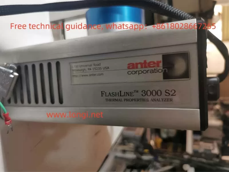
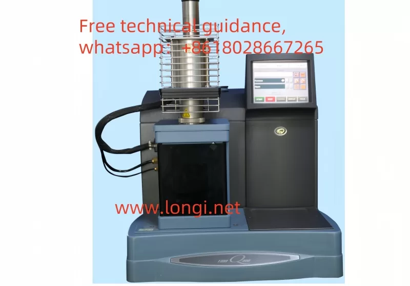
Thermal Conductivity Instruments (Including Laser Thermal Conductivity Tester, Flash Thermal Conductivity Tester, Thermal Reflectance Thermal Conductivity Tester, Thermal Conductivity Coefficient Tester, etc.) Play a Vital Role in Material Research and Testing, But May Encounter Various Faults During Use. Below Are Some Common Fault Scenarios and Corresponding Repair Methods:


I. Common Fault Scenarios

1. Unstable Readings or Display Errors

  • Possible Causes: Connection issues, sensor contamination, incorrect sample installation, unstable environmental conditions (e.g., temperature and humidity fluctuations).
  • Repair Methods: Check and reconnect the device, clean the sensor, ensure correct sample installation, and stabilize environmental conditions.

2. Readings Too High or Too Low

  • Possible Causes: Poor thermal contact, incorrect input of sample thickness or dimensions, instrument not properly calibrated.
  • Repair Methods: Ensure good thermal contact between the sample and sensor, verify and correctly input sample parameters, and calibrate according to the manufacturer’s guidelines.

3. Slow Heating or Cooling Rates

  • Possible Causes: Faulty heating or cooling elements, improper power and control settings, maintenance required.
  • Repair Methods: Check the working status of heating or cooling elements, adjust power and control settings, and perform necessary cleaning or replacement of parts.

4. Readings Affected by External Interference

  • Possible Causes: Electromagnetic interference, vibration, light interference.
  • Repair Methods: Place the instrument in a light-shielded, vibration-free, and low-electromagnetic interference environment, and use shielding materials or isolation measures to reduce interference.

5. Software Operation Difficulties

  • Possible Causes: Unfamiliarity with software functions, improper operation.
  • Repair Methods: Thoroughly read the user manual or operation guide, contact Longi Ectromechanical Company for technical support, and attend training courses to improve operational skills.
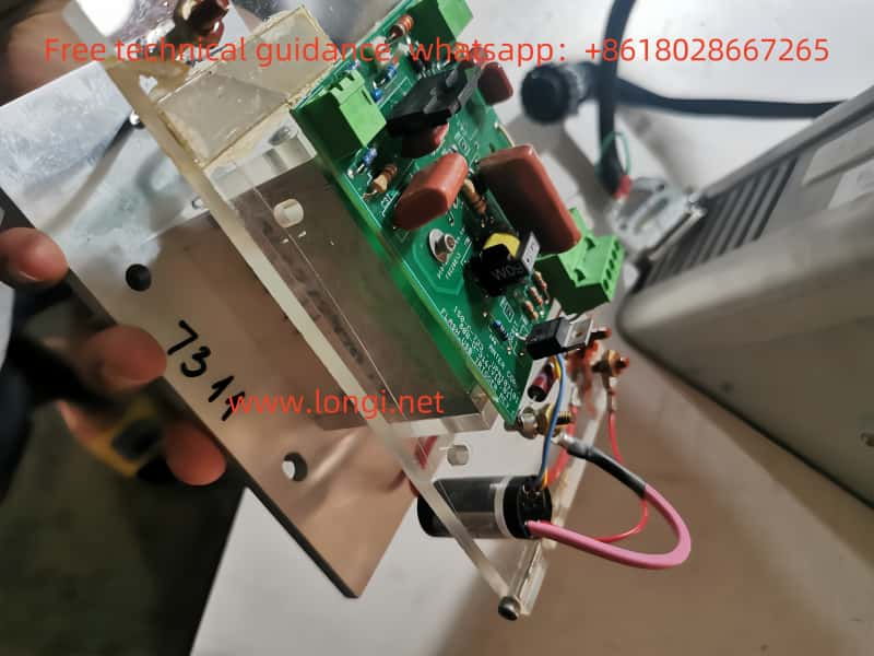
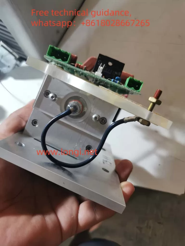
6. Hardware Faults

  • Possible Scenarios: Switch knob not fully rotated, copper wire desoldered, battery box wire broken, circuit board failure, laser head not emitting light, etc.
  • Repair Methods: Inspect the hardware components such as switch knobs, copper wire soldering, battery box wires, and circuit boards, and repair or replace as necessary.

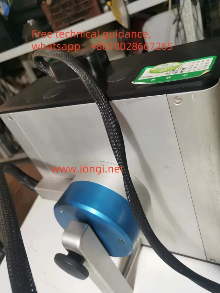
7. Light Source or Detector Faults

  • Possible Causes: Unstable light source intensity, damaged detector.
  • Repair Methods: Regularly check the working status of the light source and detector, and replace promptly if issues are found.

8. Data Acquisition System Faults

  • Possible Causes: Hardware or software faults in the data acquisition system.
  • Repair Methods: Check the working status of the data acquisition system and repair or replace if necessary.

II. Repair Method Summary

Basic Checks:

  • Inspect device connections, power supply, sensors, and sample installation.
  • Ensure stable environmental conditions (e.g., temperature and humidity).

Calibration & Adjustment:

  • Regularly calibrate the instrument following the manufacturer’s guidelines.
  • Adjust instrument settings to ensure correct measurement parameters.

Hardware Maintenance:

  • Clean sensors, heating or cooling elements, and other critical components.
  • Inspect and repair or replace damaged hardware, such as copper wires, wires, and circuit boards.

Software & Operation:

  • Thoroughly read user manuals and operation guides to ensure correct software operation.
  • Contact the manufacturer or technical support for assistance if needed.

Preventive Maintenance:

  • Regularly inspect the working status of all device components and perform necessary maintenance and replacements.
  • Establish maintenance records to track the usage status and repair history of the equipment.

Environmental Control:

  • Ensure the device operates under stable environmental conditions and avoid external interference.

By implementing these repair methods, the accuracy and reliability of thermal conductivity instruments in material research and testing can be ensured, improving the precision of measurement data.


III. Brands and Models of Thermal Conductivity Instruments Repaired by Longi Ectromechanical Company

  1. NETZSCH (Germany)
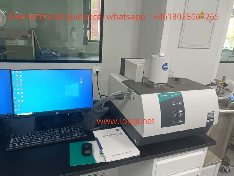
    • LFA467HT (LFA 467 HyperFlash)
    • LFA 447 NanoFlash
    • LFA 457 MicroFlash
  2. TA Instruments (USA)
    • DLF1200
    • DLF1600
    • DLF2800
  3. Linseis Thermal Analysis (Germany)
    • LFA1000
    • LFA500
  4. Thermophysical Instruments (Japan)
    • TC1200
    • TC7000
  5. C-Therm Technologies (Canada)
    • TCi Thermal Conductivity Analyzer
    • Trident Thermal Conductivity Analyzer
  6. KEM (Japan), Quick Thermal Conductivity Tester
    • QTM-500
    • QTM-710
    • QTM-700
    • TPS2500S
  7. Xiangtan Xiangyi Instrument (China)
    • LFA 4000
    • LFA 2000
    • DRH-300
    • DRH-ZD-300
    • DRH-400
    • DRH-ZD-400
    • DRH-600
    • DRH-ZD-600
    • DRE-2A
    • DRE-2B
    • DRE-2C
    • DRE-2D
    • DRE-2E
    • DRE-2D (duplicated, possibly an error)
    • DRE-2G
  8. Phoenix Laser Thermal Conductivity Instruments (China)
  9. CORE EU
  10. Hangtian Ruibo

Longi Ectromechanical Company has nearly 30 years of experience in repairing thermal conductivity instruments (including laser thermal conductivity testers, flash thermal conductivity testers, thermal reflectance thermal conductivity testers, and thermal conductivity coefficient testers). We can quickly repair various types of instruments. Additionally, we recycle and sell used thermal conductivity instruments. Please feel free to contact us for more information.

Posted on Leave a comment

ACH550 Inverter User Manual: Comprehensive Guide for Installation, Operation, and Maintenance


I. Operating Panel (Control Pad) Usage

1. Overview of Control Pad

The operating panel (control pad) of the ACH550 inverter serves as the primary interface between the user and the inverter, enabling status display, parameter setting, and operation control.

2. Basic Operations

  • Starting and Stopping:
    • Press “HAND” Button: Enters manual mode, allowing adjustment of inverter output frequency via the up and down arrow keys.
    • Press “AUTO” Button: Switches to automatic mode, where inverter operation is controlled by external signals (such as terminal signals or communication signals).
  • Display Mode Switching:
    • Access different display modes (e.g., output mode, parameter mode, assistant mode) through the menu button (MENU) on the control pad.
  • Parameter Setting:
    • In parameter mode, use the up and down arrow keys to select the parameter to modify. Press the edit button (EDIT) to enter the parameter settings, input new values using the numeric keys, and save changes with the save button (SAVE).

3. Assistant Mode

The assistant mode provides guided steps for starting and configuring the inverter, ideal for first-time users or those requiring quick setup.

II. Terminal Starting and Potentiometer Speed Control

1. Terminal Starting Wiring

  1. Connect Main Power: Wire the inverter’s input power to the corresponding terminals (U1, V1, W1).
  2. Connect Motor: Connect motor wires to the inverter’s output terminals (U2, V2, W2).
  3. Control Signal Wiring:
    • Connect the start signal (e.g., DI1) to the inverter’s digital input terminal.
    • If direction control is required, connect the direction signal to the corresponding terminal (e.g., DI2).

2. Potentiometer Speed Control Wiring

  1. Potentiometer Selection: Choose an appropriate rotary or slide potentiometer.
  2. Wiring:
    • Connect the three pins of the potentiometer to the inverter’s analog input terminals (e.g., positive, negative, and signal terminals of AI1).
    • Adjust the potentiometer knob to vary the voltage or current signal input to AI1, thereby controlling the inverter’s output frequency.

3. Parameter Setting

  • Enter parameter mode and select an appropriate macro (e.g., fan macro or general PID macro) that presets parameters suitable for specific applications.
  • Adjust parameters related to start/stop, direction control, and analog inputs based on actual wiring configurations.
Default macro HVAC wiring diagram for ACH550

III. Inverter Fault Code Analysis and Troubleshooting

1. Fault Code Inquiry

Display recent fault codes through the control pad, which correspond to different fault types.

2. Common Fault Codes and Troubleshooting Methods

  • Overcurrent Fault:
    • Cause: Motor overload, motor short circuit, improper parameter settings, etc.
    • Solution: Check motor and load conditions, adjust overload protection parameters, and confirm inverter and motor parameter compatibility.
  • Undervoltage Fault:
    • Cause: Low or fluctuating input power voltage.
    • Solution: Verify power supply voltage stability, increase input filter capacitors, or adjust undervoltage protection thresholds.
  • Overheat Fault:
    • Cause: Poor inverter cooling, high ambient temperature.
    • Solution: Improve inverter cooling conditions, such as installing additional cooling fans or reducing ambient temperature.
  • Communication Fault:
    • Cause: Communication line issues, incorrect communication parameter settings.
    • Solution: Check communication line connections, ensure communication parameter settings match the device configuration.

IV. Precautions

  • Always disconnect inverter power before performing any wiring or parameter adjustments.
  • Observe control pad status indicators and fault codes during operation, promptly addressing potential issues.
  • For complex faults or unsolvable problems, contact ABB technical support or a qualified service
Posted on Leave a comment

Vector Network Analyzer: Common Faults and Solutions”Vector Network Analyzer: Troubleshooting Guide and Repair Services for Various Brands and Models”Vector Network Analyzer: Common Faults and Solutions

I. Common Fault Phenomena

  1. Power Supply Faults:
    • Indicators: Front panel power indicator not lit, fan not rotating, network analyzer unable to start normally, or constant resetting due to unstable power supply voltage.
  2. Display Faults:
    • Manifestations: No display (black screen), scrambled screen, grayscale display. Possible causes include monitor failure, graphics processing board failure, or CPU failure.
  3. Local Oscillator Faults:
    • Issues: Local oscillator unlock, low local oscillator power resulting in high signal insertion loss, and poor local oscillator spectrum purity.
  4. Signal Path Faults:
    • Components affected: Input connectors, signal cables, attenuators, preselectors, frequency converters, intermediate frequency amplification/filtering, data acquisition and processing.
  5. Processor Faults:
    • Primarily involve processor hardware and program (software) faults, with the latter being more common.

II. Solutions

  1. Power Supply Fault Repair:
    • Check power cord connections and power outlets to ensure proper power supply.
    • Replace the power module or repair the power circuit if the power indicator is not lit or the fan does not rotate.
  2. Display Fault Repair:
    • Inspect display cable connections and related circuit boards for proper connection.
    • Replace the display or relevant circuit boards if the issue persists.
  3. Local Oscillator Fault Repair:
    • Examine local oscillator circuit boards and connections for damage or looseness.
    • Adjust the local oscillator circuit or replace relevant components if there is unlock or low power.
  4. Signal Path Fault Repair:
    • Check all components in the signal path, including input connectors, signal cables, attenuators, etc., for secure connections and proper functioning.
    • Replace or repair faulty components promptly.
  5. Processor Fault Repair:
    • Restart the instrument and check software settings for any program errors or configuration issues.
    • Reset the processor or reinstall software if the problem remains.
  6. Preventive Measures:
    • Ensure proper grounding to avoid electrostatic interference.
    • Read and follow instrument technical specifications and warning labels.
    • Pay attention to electrostatic protection, especially for exposed interfaces.
    • Maintain good instrument ventilation and avoid blocking air outlets.
    • When performing DC input, ground the equipment before connecting the power supply.

III. Brands and Models That Can Be Repaired

  1. Keysight Technologies (formerly Agilent Technologies):
    • 8753ET
    • ENA Series: E5061B, E5062A, E5063A, E5071B, E5071C, E5072, E5080A, E5080B
    • PNA Series: N5225A, N5225B, N5227A, N5227B, N5230C, N5230A, N5222A, N5221B, N5224, 5225BT, 5227, 5230C
    • PNA-X Series: N5247B, N5241A, N5241B, N5249A, N5249B
  2. Yi Zhuo Optoelectronic Technology (TFN):
    • Handheld Spectrum Analyzers: RMT714A, RMT716A, RMT717A, RMT719A, RMT720A, RMT740A, FAT130, FAT150, FAT750, FAT801, FAT811, FAT860 (5KHz-20GHz)
    • Antenna Feeder VSWR Testers: T300F, T300H (300KHZ-3GHZ)
    • 10G Ethernet Testers: T200K, T3000A, T5500A
    • Network Synthesis Testers: TT70-S1, TT70-S2, TT70-S3, TT70-S4
  3. Rohde & Schwarz:
    • ZNA Series: ZNA26, ZNA43, ZNA50, ZNA67
    • ZVA Series: ZVA8, ZVA14, ZVA24, ZVA40, ZVA50, ZVA67, ZVA110
    • ZVB Series: ZVB8, ZVB14
    • ZNB Series: ZNB20, ZNB26, ZNB40
  4. Anritsu:
    • MS4647B (ShockLine), MS46524B (ShockLine), MS46131A, MS4642B, MS4644B, MS4645B, MS4647A, MS46522A, MS46522B, MS46322, MS46121, MS46122
  5. Tektronix:
    • TTR500 Series: TTR500, TTR503A, TTR506A, MSO58LP, LPD64
    • RSA5000 Series: RSA5115B, RSA5103B, RSA5000-B40, RSA5000-VSA, RSA5000-EMI, RSA5000-AMK, RSA5000-PA
    • RSA6000 Series
    • RSA7000 Series: 7100A
  6. Copper Mountain Technologies:
    • Cobalt Series (e.g., S5180)
    • Planar Series (e.g., S5048)
    • R Series: R60, R140B, R180
    • Others: S5090, TR1300, M5045, M5065, M5090, M5180, S5045, S5065, S5085, S5180B, S5243, SC5065, SC5090, SN5090-6 to SN5090-16, C1209 to C4409, C1220 to C4220
  7. National Instruments (NI):
    • PXI Network Analyzer Series: PXI-2596, PXIe-5632, PXIE-8840
    • VirtualBench Multifunction Instruments: VB-8032, VB-8034, VB-8054, 783555-10
  8. RIGOL:
    • RSA5032, RSA5065-TG, RSA5000, RSA3000, RSA3015N, RSA3030, RSA3045N, RSA3030-TG, RSA3045, RSA3045-TG, RSA5032-TG, DSA815, DSA815-TG, DSA875, DSA875-TG, DSA832, DSA832-TG, DSA832E, DSA832E-TG, DSA705, DSA710
  9. CETC 41st Research Institute:
    • Siyi 3672 Series: 3672A, 3672B, 3672C, 3672D, 3672E
    • AV36580A: A new-generation vector network analyzer with multiple communication functions, automated testing capabilities, and wide test applications.
  10. Other Brands:
    • SAMZHE, Fluke, Spirant, Ideal Industries (USA)

Repair and Sales Services

Longi Electromechanical Company specializes in the repair of network analyzers (including wireless spectrum analyzers, antenna feeder VSWR testers, Ethernet testers, network synthesis testers, vector network analyzers, real-time spectrum analyzers, USB vector network analyzers) with nearly 30 years of experience. We provide quick repairs for various instruments and also offer sales and recycling of used network analyzers. Feel free to contact us for more information.

Posted on Leave a comment

Comprehensive Analysis of Spectrometers: Principles, Usage Methods, Common Faults, and Repair Techniques (Spectral Analyzer, Infrared Spectrometer, Raman Spectrometer, Fluorescence Spectrometer, Direct-Reading Spectrometer, UV-Vis Spectrometer, Fluorescence Spectrometer)

I. Spectrometer Fault Handling

  1. Invalid Detection, No Data Output:
    • Replace or upgrade the light source equipment.
    • Repair or clean the detector.
    • Realign the optical path.
    • Fault Causes: Insufficient light emission from the source, damaged or dusty detector, misaligned or shifted optical path.
  2. Optical Path Obstruction:
    • Clear the sample or optical path.
    • Check for damaged components or dust in the optical path and clean or replace as necessary.
    • Fault Causes: Sample residue in the optical path, blockages such as damaged components or dust.
  3. Vacuum Pump Not Starting:
    • Ensure consistency between pump and oil models, and regularly replace pump oil.
    • Adjust indoor temperature to avoid excessively low temperatures.
    • Check and manually start the pump motor via the analysis software.
    • Fault Causes: Poor viscosity or incorrect model of pump oil, temperature-related issues, control signal problems.
  4. Sudden Loss of Negative High Voltage:
    • Try unplugging and replugging the second ground wire of the control box; if unsuccessful, consider restarting the instrument.
    • Fault Cause: Vacuum value not rising for an extended period.
  5. Low Light Intensity:
    • Clean the condensing lens.
    • Clean the slit.
    • Replace the corresponding photomultiplier tube.
    • Fault Causes: Dirty condensing lens, dirty slit, degraded performance of the photomultiplier tube.
  6. Unstable Instrument Analysis Data:
    • Check and replace the rear fan of the instrument if necessary.
    • Fault Causes: Poor temperature control in the instrument’s vacuum chamber, faulty rear fan operation.
  7. Poor Communication Line Contact Leading to Computer Crash or Program Error:
    • Reconnect the communication line.
  8. Exhaust Blockage:
    • Replace the exhaust pipe with a transparent plastic tube and regularly purge the exhaust line.
    • Fault Causes: Blocked argon exhaust line, debris in the lower bend of the spark chamber, debris at the inlet of the argon filter.
  9. Power, Connection, or Software Issues:
    • Check for proper power connection, damaged or loose power cords.
    • Ensure correct and undamaged connection of cables.
    • If software issues occur, attempt reinstallation or updating.
  10. Other Maintenance and Calibration:
    • Regularly clean the optical components of the spectrometer and perform calibration to ensure accuracy.

Note: The above solutions are for reference only. For specific faults, it is recommended to contact Rongji Electromechanical for professional repair and support.

II. Supported Spectrometer Brands by Rongji Electromechanical

  1. Niton Spectrometers (Thermo Fisher Scientific):
    • Niton XL2, Niton XL2 Plus, Niton XL5 Plus, Niton DXL Precious Metal Analyzer, Niton XL2 100G General Metal Analyzer, Niton Apollo Handheld LIBS Analyzer.
  2. Yokogawa Spectrometers:
    • AQ6370, AQ6370B, AQ670C, AQ6370D, AQ6374, AQ6375, AQ6376, AQ6315E, AQ6317B, AQ6317C, AQ6319, AQ6330.
  3. Hitachi Spectrometers:
    • OE720, OE750, PMI-MASTER Smart, X-Supreme8000, LAB-X5000.
  4. HORIBA Spectrometers:
    • FluoroMax Plus, VS70-PDA-HDR, Duetta, Ultima Expert, MicroHR Series, MicOS, 1000M Series, HR Evolution, iHR320, XploRA PLUS XS, T64000, HE.
  5. Malvern Spectrometers:
    • Mastersizer 3000+ Ultra, Mastersizer 3000+ Pro, Mastersizer 3000+ Lab, Mastersizer 3000E.
  6. Beckman Coulter Spectrometers:
    • DU 640, DU 720, DU 730.
  7. Shimadzu Spectrometers:
    • ICPE-9000, ICPE-9800, ICPS-7000, ICPS-7510, ICPS-8100, EDX-LE Plus, EDX-GP, EDX-7200, EDX-8000, EDX-8100, IRSpirit, IRPrestige-21, PDA-5000, PDA-7000, PDA-8000, SolidSpec-3700, 3700DUV, RM-3000, RF-6000, UV-1900I.
  8. Thermo Fisher Scientific Spectrometers:
    • Nicolet Summit, ARL 3460, ARL 4460, ARLeasySpark, DXRxi, DXR, DXR™ 3, WDXRF, EDXRF, XRFXRD, ARL EQUINOX.
  9. Bruker Spectrometers:
    • VERTEX Series, ALPHA II, INVENIO, IFS 125HR, MPA II, TANGO, MATRIX-F, SENTERRA II, BRAVO, MultiRAM, RAM II, TXRF S4 TSTAR, S2 PICOFOX, M4 TORNADO, S1 TITAN, Q4 TASMAN, Q2, Q2L, Q8.
  10. Agilent Spectrometers:
    • Agilent 8453, Agilent Cary 60, Agilent Cary 100, Agilent Cary 300, Agilent 55, Agilent 4100 MP-AES, Agilent 710/715 Series, Agilent 5110.
  11. HORIBA Additional Models:
    • HR Evolution, iHR320, XploRA PLUS XS, T64000, HE.
  12. PerkinElmer Spectrometers:
    • Spectrum Two, Spectrum 3, PinAAcle 500, PinAAcle 900F.
  13. Tianrui Instruments:
    • EDX Series, SUPERXRF1050, Explorer8000 Series, SEE 100, SEE 200, ZSX Primus Series, XEPOS.
  14. Nanjing Sanxiang Spectrometers:
    • THICK800A, EDX4500H.

Longi Electromechanical offers long-term maintenance for various types of spectrometers, including infrared, Raman, fluorescence, direct-reading, UV-Vis, and more. With nearly 30 years of experience, we can quickly repair various instruments. Additionally, we recycle and sell used spectrometers. For more information, please contact us.

Posted on Leave a comment

PowerFlex 750 Series AC Drive User Guide

PowerFlex 750 Series AC Drive User Guide

1. Operation Panel (Keypad) Usage

The operation panel (keypad) of the PowerFlex 750 series AC drive serves as the primary interface for user interaction. It allows users to navigate menus, set parameters, and view status information.

Navigation and Selection: Use the arrow keys to navigate through menus and the “Select” button to enter specific settings or parameter editing mode.

Parameter Editing: In edit mode, enter or adjust parameter values using the numeric keys or arrow keys.

Saving and Exiting: After making changes, use the “Save” button to save modifications and the “Exit” button to return to the previous menu or the main interface.

Status Viewing: Select the appropriate option from the menu to view the drive’s output frequency, current, voltage, fault codes, and other status information.

Rockwell Powerflex 755 Series VFD Status Indicator Light Description

2. Open-Loop V/F Control Parameter Settings

In open-loop V/F (Volts per Hertz) control mode, the drive regulates the motor speed by adjusting the ratio between the output voltage and frequency. Here are guidelines for setting key parameters:

  • P35 (Motor Control Mode): Set to “V/Hz” mode to enable open-loop V/F control.
  • P25 (Motor Nameplate Voltage): Enter the motor’s rated voltage.
  • P27 (Motor Nameplate Frequency): Input the motor’s rated frequency.
  • P60 (V/F Curve Settings): Adjust the V/F curve as needed to optimize motor performance.
  • P520/P521 (Maximum Forward/Reverse Speed): Set the maximum operating frequency limits for the motor.
I/O Wiring Diagram for Rockwell Powerflex 755 Series VFD

3. Terminal Start and Potentiometer Speed Adjustment Wiring and Parameter Settings

Wiring Instructions:

  • Main Power and Control Power Connection: Connect the three-phase main power and (if required) control power as specified in the manual.
  • Motor Connection: Wire the motor’s three-phase leads to the U, V, W output terminals.
  • Start/Stop Terminal Connection: Connect the contacts of the external start/stop buttons to the drive’s DI (Digital Input) terminals and configure the related parameters.
  • Potentiometer Speed Adjustment Connection: Connect the potentiometer’s wiper to the AI (Analog Input) terminal for speed regulation.

Parameter Settings:

  • Digital Input Configuration: Configure relevant parameters to assign DI terminals for start/stop functions.
  • Analog Input Configuration: Ensure AI terminals are set as the speed reference source and adjust the input range to match the potentiometer’s output range.
  • Speed Reference Selection: Specify the analog input as the source for speed references in the parameters.

4. Fault Code Analysis and Troubleshooting Summary

According to the fault code list provided in the manual (pages 316-323, fault numbers 0-155), here are summaries of a few common faults, their possible causes, and troubleshooting methods:

  • F001: Overcurrent Protection. Check for motor overload, stable power supply voltage, and short circuits in the output circuit.
  • F002: Overvoltage Protection. Verify that the input voltage is within the allowed range and consider installing a voltage stabilizer or adjusting the input filter.
  • F003: Undervoltage Protection. Check if the power supply voltage is too low and confirm correct power line connections.
  • F004: Overheat Protection. Inspect the drive and motor cooling, clean dust from the heat sink, and ensure proper ventilation.
  • F005: Communication Failure. Check communication line connections, verify correct communication parameter settings (including baud rate, data bits, etc.).

Please note, the above fault codes are examples, and specific fault codes and their solutions should be referenced directly from the manual.

5. General Troubleshooting Steps

  • Check Fault Code: Read and record the fault code on the operation panel.
  • Consult the Manual: Look up the corresponding fault description, possible causes, and solutions in the manual.
  • Perform Preliminary Checks: Examine power sources, motors, communication lines, etc.
  • Reset the Drive: If initial checks reveal no issues, attempt to reset the drive to clear temporary faults.
  • Advanced Diagnostics: If problems persist, professional tools may be
Posted on Leave a comment

CHF100A Series Vector Universal VFD Usage Guide:Usage of Operation Panel, Startup and Debugging of VFD Terminal Mode, Analysis and Solutions for VFD Fault Codes

I. Operation Panel (Keyboard) Usage

The operation panel (keyboard) of the CHF100A Series Vector Universal VFD serves as the primary interface for VFD control and parameter setting. Here are the basic keyboard operation methods:

  1. Power-on and Display:
    • Upon connecting the VFD’s power supply, the display on the operation panel will illuminate, showing the current status or default parameters.
  2. Key Functions:
    • PRG: Programming key, used to enter or exit parameter setting mode.
    • SHIFT: Shift key, combined with numeric keys to select or modify high-order digits of parameters.
    • ESC: Escape key, used to exit the current setting or menu.
    • ENT: Enter key, used to confirm current settings or selections.
    • DATA: Data toggle key, used in some settings to switch between displaying different data items.
  3. Parameter Setting Procedure:
    • Press the PRG key to enter parameter setting mode.
    • Use arrow keys (if equipped) or SHIFT + numeric keys to select the desired parameter number.
    • Press the ENT key to enter the parameter’s setting interface.
    • Modify the parameter value using arrow keys or numeric keys.
    • Press the ENT key again to confirm the setting.
    • Press the ESC key to exit parameter setting mode.
INVT VFD CHF100A keyboard operation diagram

II. VFD Terminal Startup and Potentiometer Speed Regulation Wiring

  1. Terminal Startup Wiring:
    • Refer to the electrical wiring diagram in the manual (typically around page 75) to locate the input terminals related to startup (e.g., S1, S2).
    • Connect the external startup signal (e.g., pushbutton switch, PLC output) to the corresponding startup terminals.
    • Configure parameters as needed to ensure the VFD recognizes and responds to these startup signals.
  2. Potentiometer Speed Regulation Wiring:
    • Locate the analog input terminals (e.g., AI1, AI2) on the VFD, which receive analog signals from the potentiometer.
    • Connect the wiper of the potentiometer to the AI1 or AI2 terminal, and the fixed terminal to the common ground (e.g., COM).
    • Adjust the potentiometer to vary the output signal, thereby controlling the VFD’s output frequency and motor speed.
CHF100A inverter wiring diagram

III. VFD Fault Code Analysis and Troubleshooting

When a CHF100A Series VFD encounters a fault, it displays the corresponding fault code on its screen. Here are some common fault codes, their analysis, and troubleshooting methods:

  1. OC (Overcurrent):
    • Cause: Excessive motor or load, output short circuit, faulty cabling or wiring.
    • Solution: Check the motor and load to ensure they are within normal ranges; inspect cabling and wiring for correctness; increase deceleration time or reduce acceleration current.
  2. OV (Overvoltage):
    • Cause: Excessive input voltage, inadequate deceleration time.
    • Solution: Verify that the input voltage meets specifications; increase deceleration time.
  3. UV (Undervoltage):
    • Cause: Insufficient input voltage, power supply failure.
    • Solution: Check the power supply voltage for normalcy; inspect power lines and fuses for integrity.
  4. OH (Overheating):
    • Cause: Elevated ambient temperature, poor ventilation, clogged heat sink.
    • Solution: Improve ventilation to enhance cooling, reduce ambient temperature; clean dust and debris from the heat sink.

Please note that these are exemplary analyses and solutions. Always refer to actual circumstances and detailed instructions in the manual. When dealing with any electrical fault, adhere strictly to safety procedures and consider power disconnection to avoid electrical shock risks.

Posted on Leave a comment

User Guide for Delta VFD MS300 Series: Operation Panel Usage, Startup and Debugging of VFD Terminal Mode, Analysis and Solutions for VFD Fault Codes

Delta VFD MS300 Series User Guide

I. Operating Panel Usage

  1. Power-On and Display
    • Upon powering on, the VFD automatically conducts a self-test and then enters standby mode. The display on the operating panel shows the current status and parameters.
  2. Function Key Operations
    • RUN/STOP Button: Press RUN to start the VFD and STOP to halt its operation.
    • Direction Selection (FWD/REV): Used to select forward or reverse rotation for the motor.
    • Frequency Adjustment Keys: Adjust the output frequency using the up and down arrow keys. In automatic mode, these keys may be disabled.
    • MENU Button: Enters the main menu, allowing access and modification of various settings.
    • ENTER Button: Confirms the current selection or enters setup mode.
    • ESC Button: Exits the current setup or returns to the previous menu level.
  3. Parameter Settings
    • Navigate to the parameter settings menu, use the arrow keys to select the parameter to modify, press ENTER to enter edit mode, adjust the parameter value with the up/down arrow keys, and confirm with ENTER.
digital keypad KPC-CC01 Functional Description

II. Wiring for Terminal Start and Potentiometer Speed Control

  1. Starting Terminal Wiring
    • Forward Start (FWD): Connect the external control signal to the VFD’s forward start terminal (e.g., FWD).
    • Reverse Start (REV): For reverse rotation, connect the signal to the reverse start terminal (e.g., REV). Typically, forward and reverse cannot be activated simultaneously.
    • Stop: Connect the stop signal to the VFD’s stop terminal to interrupt output.
  2. Potentiometer Speed Control Wiring
    • Connect a potentiometer to the analog input terminal (e.g., AVI or ACI) of the VFD. Attach the two fixed ends of the potentiometer to the VFD’s power supply (e.g., +10V and GND), and connect the sliding end to the VFD’s analog input terminal.
    • According to the parameter settings in the manual (e.g., parameter 03-00), configure the relevant parameter to “frequency command” so that the VFD can adjust its output frequency based on the voltage signal from the potentiometer.
MS300 vfd standard wiring diagram

III. Parameter Configuration

  1. Basic Parameter Settings
    • Maximum Operating Frequency (Parameter 01-00): Set the maximum output frequency based on the motor specifications.
    • Acceleration/Deceleration Time (Parameters 01-12 through 01-19): Configure appropriate acceleration and deceleration times to avoid mechanical shocks and overcurrents, tailored to your application’s needs.
    • Starting Frequency (Parameter 01-09): Set the initial frequency at startup to mitigate starting surges.
  2. Input/Output Terminal Configuration
    • Multi-function Input Terminals (Parameters 02-01 through 02-07): Assign each terminal’s function according to your control requirements, such as start, stop, and direction control.
    • Analog Input Configuration (e.g., Parameter 03-00): Specify the function of AVI, ACI, and other analog input terminals, such as frequency reference or torque control.
  3. Protection Parameters
    • Overcurrent Protection (Parameters 06-03 through 06-04): Configure the overcurrent protection threshold and duration to safeguard the motor and VFD.
    • Overvoltage/Undervoltage Protection (Parameters 06-00, 06-01): Set voltage protection thresholds to ensure stable operation amidst voltage fluctuations.

IV. Fault Code Analysis and Resolution

  1. Overcurrent (OC)
    • Cause: Excessive motor load, too short acceleration time, motor malfunction, etc.
    • Resolution: Inspect the motor and load conditions, adjust the acceleration time, and check for motor damage.
  2. Overvoltage (OV)
    • Cause: Excessive input voltage, too short deceleration time, insufficient braking resistance, etc.
    • Resolution: Verify the input voltage, adjust the deceleration time, and consider adding braking resistance.
  3. Undervoltage (LV)
    • Cause: Low input voltage, voltage drop due to long power lines, etc.
    • Resolution: Check the power supply voltage and optimize power line layout.
  4. Overheating (OH)
    • Cause: High ambient temperature, poor heat dissipation, excessive load, etc.
    • Resolution: Improve cooling conditions, reduce the load, and inspect and clean the cooling fan.
  5. Communication Fault
    • Cause: Communication line issues, incorrect parameter settings, address conflicts, etc.
    • Resolution: Examine the communication lines, verify communication parameter settings, and ensure unique device addresses.

By following this guide, you can effectively use and maintain the Delta VFD MS300 series, ensuring stable operation and optimal performance.

Posted on Leave a comment

ACS510 Variable Frequency Drive (VFD) User Guide: Operating Panel Usage, Terminal Mode Startup and Speed Adjustment Methods, Fault Analysis and Solution Methods

ACS510 Variable Frequency Drive (VFD) User Guide

I. Operating Panel Usage

  1. Power On/Off
    Before powering on, ensure all connections are correct and the surrounding environment meets safety standards.
    Use the power switch on the operating panel to turn the power on or off.
  2. Mode Switching
    LOC/REM Button: Used to switch the control mode of the VFD. Press and hold this button for 2 seconds to toggle between Local Control (LOC) and Remote Control (REM) modes.
    In Remote Control mode, the VFD can be controlled via external terminals or communication interfaces.
  3. Display and Operation
    Display: The LCD screen on the operating panel displays various status information of the VFD, such as motor speed, current, voltage, etc.
    Button Operation: Use the Up/Down arrow buttons to navigate through menus and parameters. The MENU/ENTER button is used to enter and exit menus, while the EXIT/RESET button exits to the previous menu level or resets settings.
  4. Parameter Modification
    Enter the parameter mode, select the parameter group to be modified, adjust the parameter value using the Up/Down arrow buttons, and save the settings with the SAVE button.
ACS510 drive operation panel basic function diagram

II. VFD Terminal Start-up and Potentiometer Speed Control Wiring Methods

  1. Terminal Start-up Wiring
    External Start Signal: Typically, connect the external start signal (e.g., a push-button switch) to the DI1 (Digital Input 1) terminal of the VFD and connect the common terminal to DI COM (Digital Input Common).
    Direction Control: If direction control is required, connect the direction signal to the DI2 terminal.
    Run Enable: Some applications may require an additional run enable signal, which can be connected to the appropriate DI terminal.
  2. Potentiometer Speed Control Wiring
    Analog Input Wiring: When using a potentiometer for speed control, connect the output terminal of the potentiometer to the AI1 (Analog Input 1) terminal of the VFD and connect AI COM (Analog Input Common) to the common terminal.
    Parameter Setting: In parameter group 11, set Reference 1 Select (REF1 SELECT) to AI1 to ensure the VFD receives the speed reference signal from AI1.
standard macro of ACS510 drive function diagram

III. Parameter Settings

  1. Selecting Standard Macros
    Enter parameter group 99, find parameter 9902 (APPLIC MACRO), set it to 1, and select the ABB standard macro. This will automatically set a predefined set of parameters suitable for most general applications.
  2. Motor Parameter Settings
    Input the motor’s rated voltage (9905 MOTOR NOM VOLT), rated current (9906 MOTOR NOM CURR), rated frequency (9907 MOTOR NOM FREQ), rated speed (9908 MOTOR NOM SPEED), and rated power (9909 MOTOR NOM POWER), ensuring these parameters match the data on the motor’s nameplate.
  3. Other Important Parameters
    Acceleration Time (2202 ACCELER TIME 1): Sets the time required for the motor to accelerate from rest to maximum frequency.
    Deceleration Time (2203 DECELER TIME 1): Sets the time required for the motor to decelerate from maximum frequency to rest.
    Maximum Output Frequency (2008 MAXIMUM FREQ): Sets the maximum frequency output of the VFD.

IV. VFD Fault Code Analysis and Resolution Methods

  1. Overcurrent Fault (Code 1: OVERCURRENT)
    Cause: Motor overload, excessively short acceleration time, motor fault, etc.
    Solution: Check if the motor is overloaded, increase the acceleration time, inspect motor and cable connections.
  2. DC Overvoltage (Code 2: DC OVERVOLT)
    Cause: Excessively high input voltage, excessively short deceleration time, improper braking resistor, etc.
    Solution: Check the input voltage, increase the deceleration time, inspect the braking resistor configuration.
  3. Overtemperature Fault (Code 3: DEV OVERTEMP)
    Cause: Excessively high ambient temperature, faulty cooling fan, dust accumulation, etc.
    Solution: Lower the ambient temperature, clean dust, replace faulty fan.
  4. Motor Stall (Code 12: MOTOR STALL)
    Cause: Motor or load stall, improper motor selection, etc.
    Solution: Inspect the motor and load, ensure correct motor selection.
  5. Panel Loss (Code 10: PANEL LOSS)
    Cause: Communication fault between the control panel and the VFD.
    Solution: Check control panel connections, communication settings, and cables.

Please follow this guide for operation and adjust parameters and wiring according to actual conditions. If any issues arise, please contact us technical support promptly.

Posted on Leave a comment

JACT AT500 Inverter Operation Guide and Fault Handling Summary

AT500 Inverter Operation Guide and Fault Handling Summary


I. AT500 Inverter Operation Panel Usage

  1. Operation Panel Layout and Indicator Description:
    • Introduces the display, buttons (RUN, STOP/RES, MK, Λ, V, >>, etc.) on the operation panel and their functions.
    • Explains the meanings of various indicators (Run, Alm, Hz, A, V, %, rpm, F/R, etc.).
  2. Menu and Parameter Settings:
    • Describes the three-level menu mode (function parameter group, function code, function code modification) and its operation method.
    • Elaborates on how to view and modify various inverter parameters through the operation panel.
  3. Operation Mode Control:
    • Introduces starting the inverter via the RUN button and stopping it via the STOP/RES button.
    • Explains the jog operation function and its debugging applications.
Function diagram of AT500 inverter operation panel buttons

II. Terminal Control and External Potentiometer Debugging Mode Setup

  1. Terminal Control Setup:
    • Guides users to enter the F0 parameter group and set F0.02 to 1 to enable terminal control.
    • Demonstrates how to assign functions to each input terminal through the F2 parameter group and explains wiring requirements.
  2. External Potentiometer Debugging Mode:
    • Teaches users to set F0.03 or F0.04 to AI3 (keyboard potentiometer) to adjust the output frequency by rotating the potentiometer knob.
JACT AT500 inverter wiring diagram

III. Inverter Fault Code Classification and Troubleshooting Methods

  1. Overcurrent Faults (Err02-Err04):
    • Lists possible causes (output circuit short circuit, too short acceleration/deceleration time, etc.).
    • Provides solutions (check output circuit, adjust acceleration/deceleration time, etc.).
  2. Overvoltage Faults (Err05-Err07):
    • Analyzes fault causes (excessively high input voltage, external force during deceleration, etc.).
    • Offers remedies (adjust input voltage, eliminate external force during deceleration, etc.).
  3. Undervoltage Fault (Err09):
    • Describes fault causes (instantaneous power failure, low input voltage, etc.).
    • Suggests solutions (check input power supply, adjust voltage range, etc.).
  4. Overload Faults (Err10-Err11):
    • Indicates faults may be caused by excessive load, motor stall, etc.
    • Proposes reducing the load, checking the motor and mechanical conditions, etc.
  5. Input/Output Phase Loss Faults (Err12-Err13):
    • Analyzes fault causes (input power phase loss, faulty output wires or motor, etc.).
    • Offers advice on checking power and motor, troubleshooting peripheral faults, etc.
  6. Module Overheating Fault (Err14):
    • Explains fault causes (high ambient temperature, blocked air ducts, etc.).
    • Emphasizes the importance of reducing ambient temperature, cleaning air ducts, replacing fans, etc.
  7. Communication Fault (Err16):
    • Mentions possible causes (incorrect communication parameter settings, faulty communication cables, etc.).
    • Suggests checking communication parameters, cables, and the host computer.
Posted on Leave a comment

POWTRAN PI500 Series Current Vector Inverter: User Guide & Essential Features

This comprehensive guide covers the key features and essential operations of the POWTRAN PI500 Series high-performance current vector inverter, including parameter adjustment via the panel, start/stop control through terminals, external potentiometer debugging mode configuration, and multi-speed settings.

VFD panel operation method of POWTRAN

1. Adjusting Parameters via the Inverter Panel

To adjust parameters using the inverter’s keypad, follow these steps:

  • Enter Menu: Press the PRG key to enter the parameter setting mode.
  • Select Parameter Group: Use the arrow keys to select the desired function parameter group (e.g., F0 group for basic function parameters).
  • Select Function Code: Within the selected group, use the arrow keys to choose the function code you wish to modify.
  • Adjust Parameter Value: Use the increment/decrement keys to adjust the parameter value or enter a new value directly with the numeric keys.
  • Save Settings: After making changes, press ENTER to confirm and save your settings.

Note: Some parameters cannot be modified during operation and require the inverter to be stopped first. Always consult the manual thoroughly before adjusting parameters.

Wiring Diagram of POWTRAN PI500

2. Starting and Stopping the Inverter via Terminals

To control the inverter’s start and stop via external terminals, follow these configuration steps:

  • Set Command Source: Set F0.11 (Command Source Selection) to “1” (Terminal Control) to enable external terminal operation.
  • Assign Terminal Functions: Use F1 group function codes (e.g., F1.00, F1.01) to assign specific input terminals (e.g., DI1, DI2) for forward, reverse, stop, and other functions.
  • Wiring: Connect the external control signal wires correctly to the designated input terminals based on your settings.

To start the inverter, apply a closure signal to the forward terminal (e.g., DI1). To stop, apply a stop signal to the stop terminal (which may be DI2, depending on your configuration) or disconnect the forward signal.

External potentiometer analog quantity given wiring diagram of PI500

3. Setting External Potentiometer Adjustment Mode

To configure the inverter for external potentiometer adjustment, follow these steps:

  • Configure AI1 Input:
    • Wiring: Connect the external potentiometer’s output to the inverter’s AI1 and GND terminals.
    • Set Input Range: Adjust F1.12 (AIC1 Minimum Input) and F1.14 (AIC1 Maximum Input) based on the potentiometer’s output range to ensure the inverter interprets the signals correctly.
  • Select Frequency Source: Set F0.03 (Main Frequency Source Setting) to “2” (Analog AI1 Setting) to use the AI1 input signal as the frequency reference.
  • Start Adjustment: Once configured, rotating the external potentiometer will adjust the inverter’s output frequency.
Multi speed functional wiring diagram of PI500

4. Introduction to Multi-speed Functionality

The multi-speed feature enables preset speed profiles, allowing quick switching between them via external signals.

  • Preset Speeds: Use E1 group function codes (E1.00 to E1.15) to set up to 16 different speed segments, each representing a percentage of the maximum frequency.
  • Assign Terminal Functions: Allocate input terminals (e.g., S1, S2, S3, S4) through F1 group function codes to select between the multi-speed segments based on their combinational states.
  • Set Acceleration/Deceleration Times: Customize acceleration and deceleration times for seamless speed transitions using parameters like F0.13 to F0.15.
  • Choose Speed Switching Method: Optionally, utilize external signals (high-speed pulses, communication signals) for dynamic speed segment switching.

To utilize the multi-speed feature, manipulate the allocated external terminals or transmit corresponding control signals. The inverter will then adjust its operating frequency according to the activated speed segment.

Notes:

  • Ensure speed segment settings align with the motor and inverter’s capabilities.
  • Carefully consider the mechanical load’s response to acceleration and deceleration when setting these times.

By following these configurations, you can flexibly manage the inverter’s speed to meet various process demands, while also benefiting from the manual’s detailed guidance for troubleshooting and maintaining optimal performance.

To learn more about the usage of PI500 VFD, you can download its manual from Google Drive or contact our service:https://drive.google.com/file/d/1zCUn1w6h9rEkvbP0yPJ1qAA5–T7axBt/view?usp=sharing