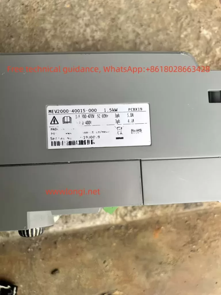
SHZK INVERTER ZK880 Series User Guide
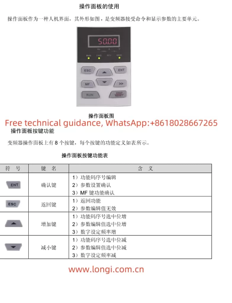
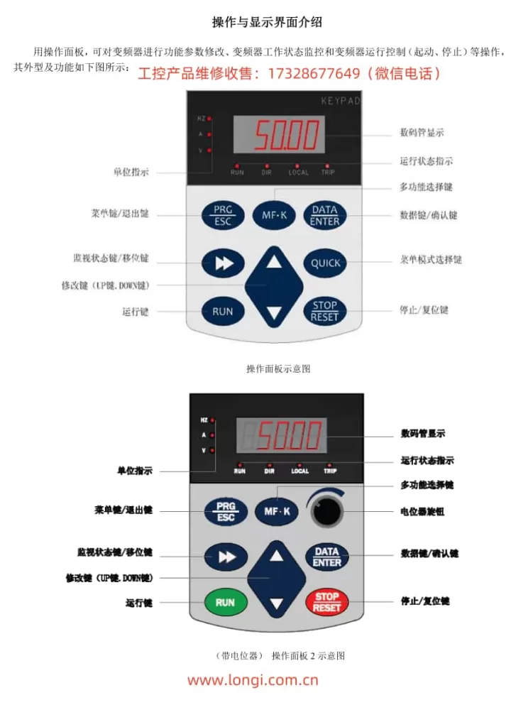
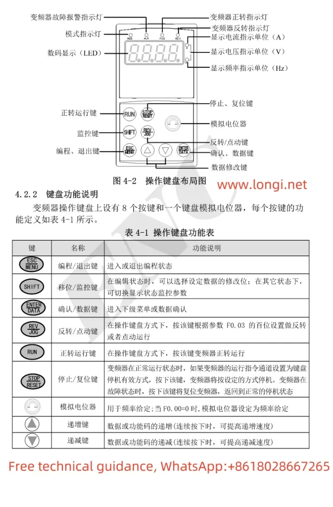
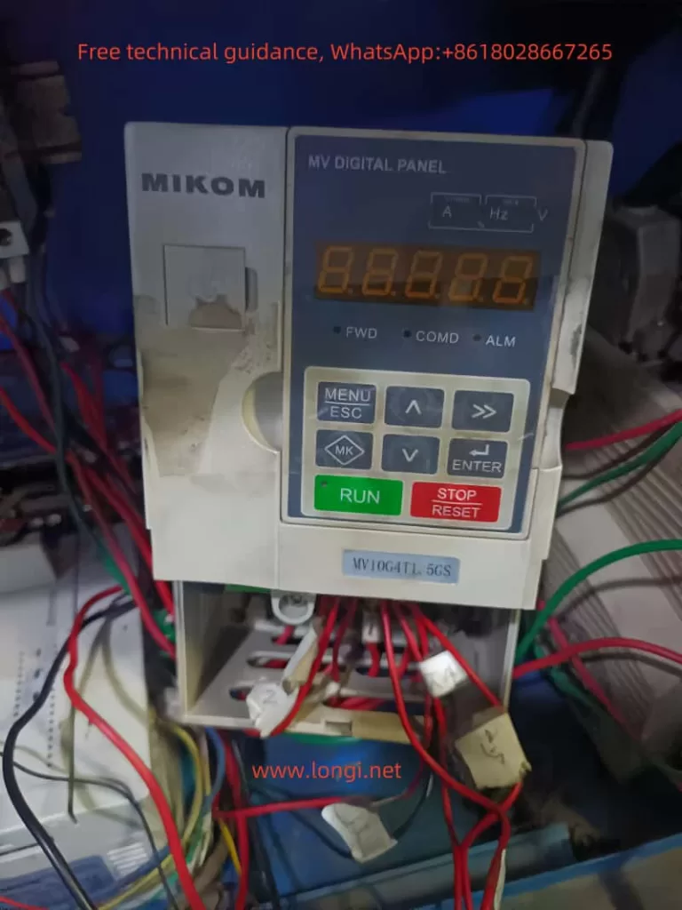
I. Operation Panel Function Introduction
The SHZK INVERTER ZK880 series provides an intuitive operation panel, facilitating easy setup and control of the inverter.
II. Setting Key Parameters
1. Acceleration and Deceleration Time
To set the acceleration and deceleration time:
- Press the PRG key to enter the programming mode.
- Use the ▲ and ▼ keys to navigate to the relevant parameters (e.g., F0-17 for acceleration time, F0-18 for deceleration time).
- Use the ▲ and ▼ keys to adjust the values.
- Press the ENT key to confirm the settings.

2. Starting Frequency
To set the starting frequency:
- Enter the programming mode by pressing the PRG key.
- Navigate to the starting frequency parameter (F6-03).
- Adjust the value using the ▲ and ▼ keys.
- Confirm the setting with the ENT key.
3. Upper and Maximum Frequency
To set the upper and maximum frequency:
- Enter the programming mode.
- Navigate to the maximum frequency parameter (F0-10).
- Adjust the value to the desired maximum frequency.
- For the upper frequency limit, navigate to F0-12 and set accordingly.
- Confirm each setting with the ENT key.
4. Minimum Frequency
To set the minimum frequency:
- Enter the programming mode.
- Navigate to the minimum frequency parameter (F0-14).
- Adjust the value to the desired minimum frequency.
- Confirm with the ENT key.
5. Current and Power
To monitor or limit the current and power:
- The current and power values can be monitored in real-time via the operation panel or through the monitoring parameters (U0-04 for output current, U0-05 for output power).
- For current limiting, navigate to the relevant protection parameters (e.g., F9-06 for over-current trip level).
- Adjust the values as needed and confirm with the ENT key.
6. Restoring Initialization Parameters
To restore the inverter to its factory settings:
- Power off the inverter.
- Hold down the STOP/RES key while powering on the inverter.
- Continue holding the key until the display shows “rE”, indicating that the parameters have been reset.
- Release the key and allow the inverter to restart.
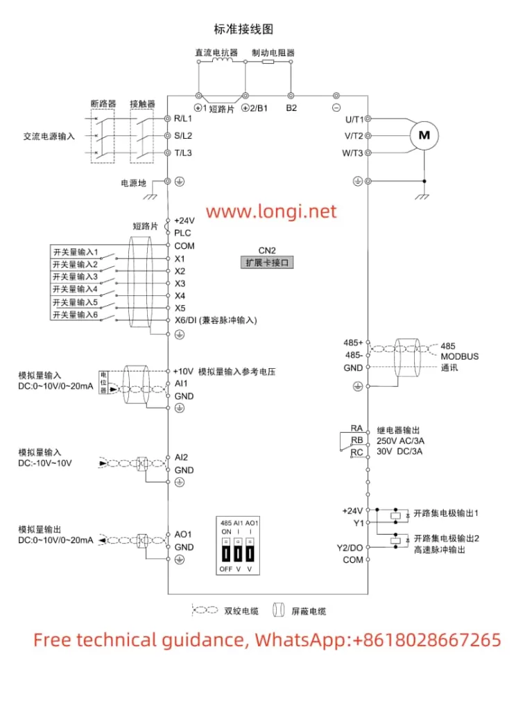
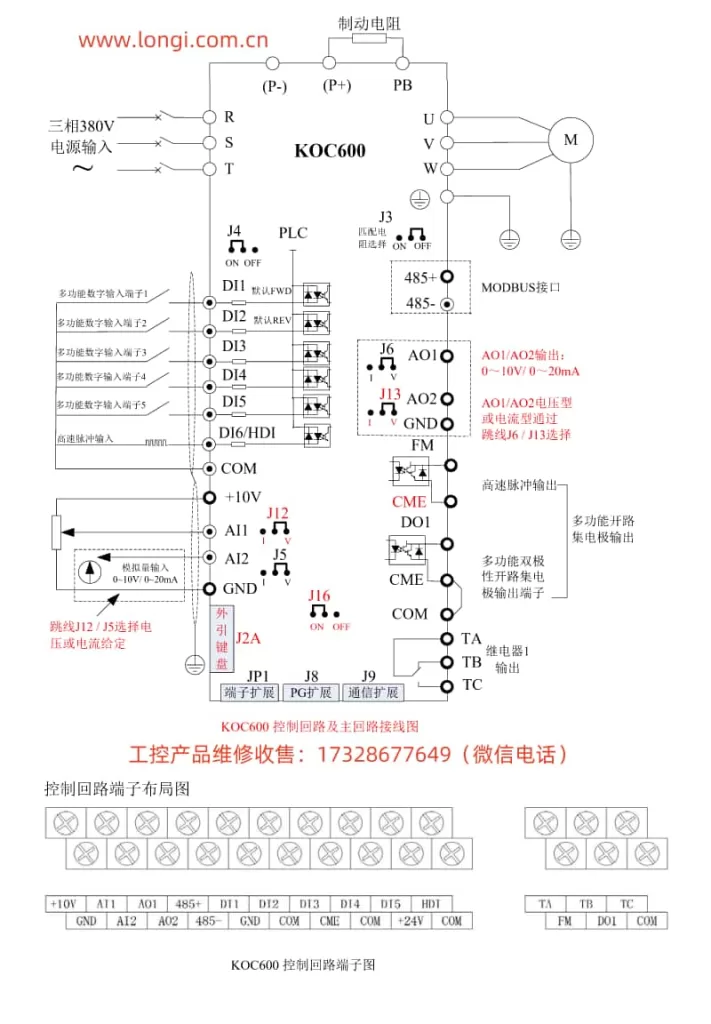
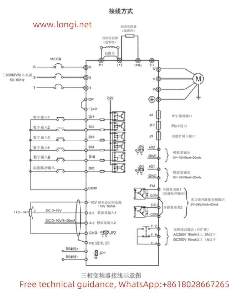
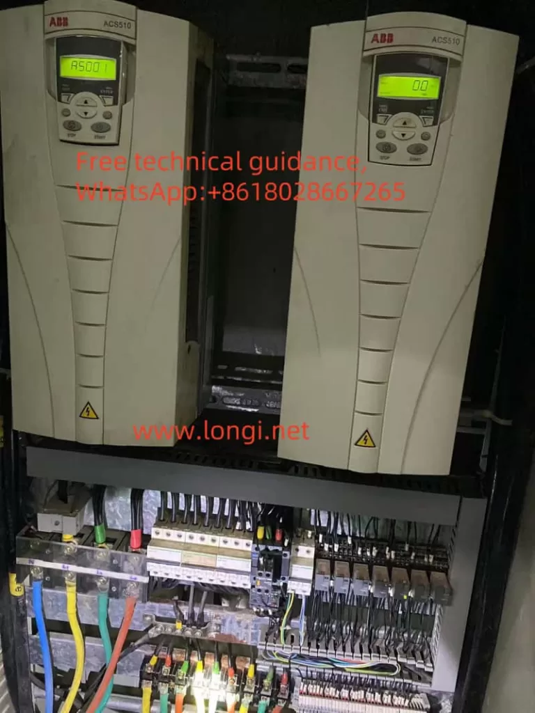
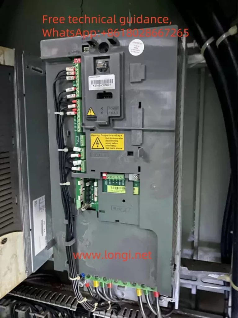
III. Terminal Start and Direction Control
1. Terminal Start
To start the inverter via terminals:
- Ensure the command source is set to terminal control (F0-02 = 1).
- Connect the appropriate terminal (e.g., FWD for forward rotation) to a closed contact or power source.
- The inverter will start running according to the terminal configuration.
2. Direction Control
To control the rotation direction:
- Ensure the necessary terminals (e.g., FWD for forward, REV for reverse) are properly connected.
- Activate the corresponding terminal to start the inverter in the desired direction.
- For reversing, deactivate the forward terminal and activate the reverse terminal.
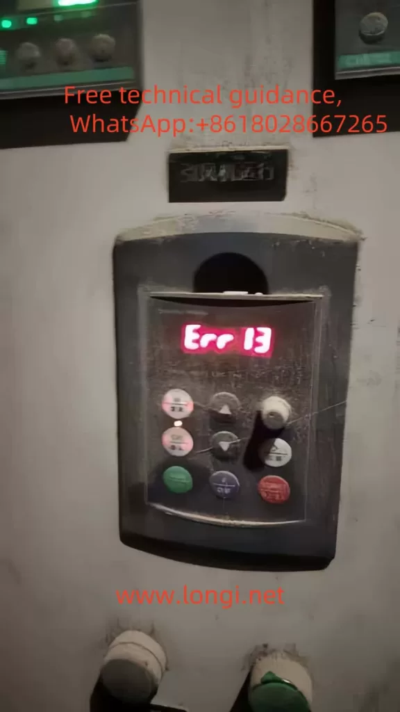
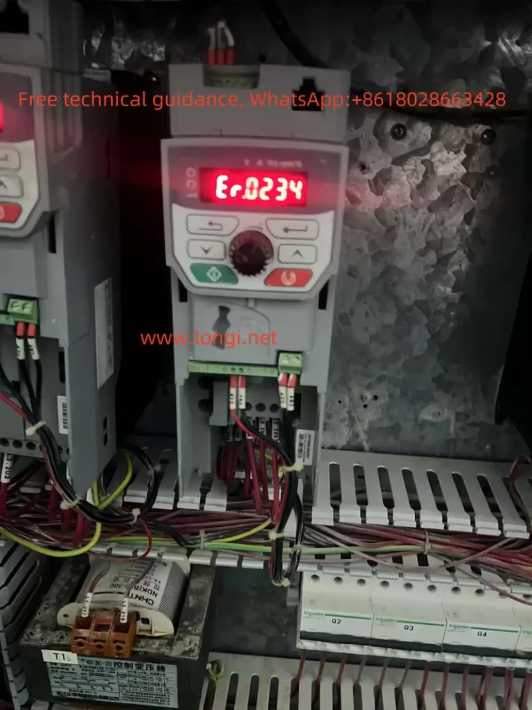
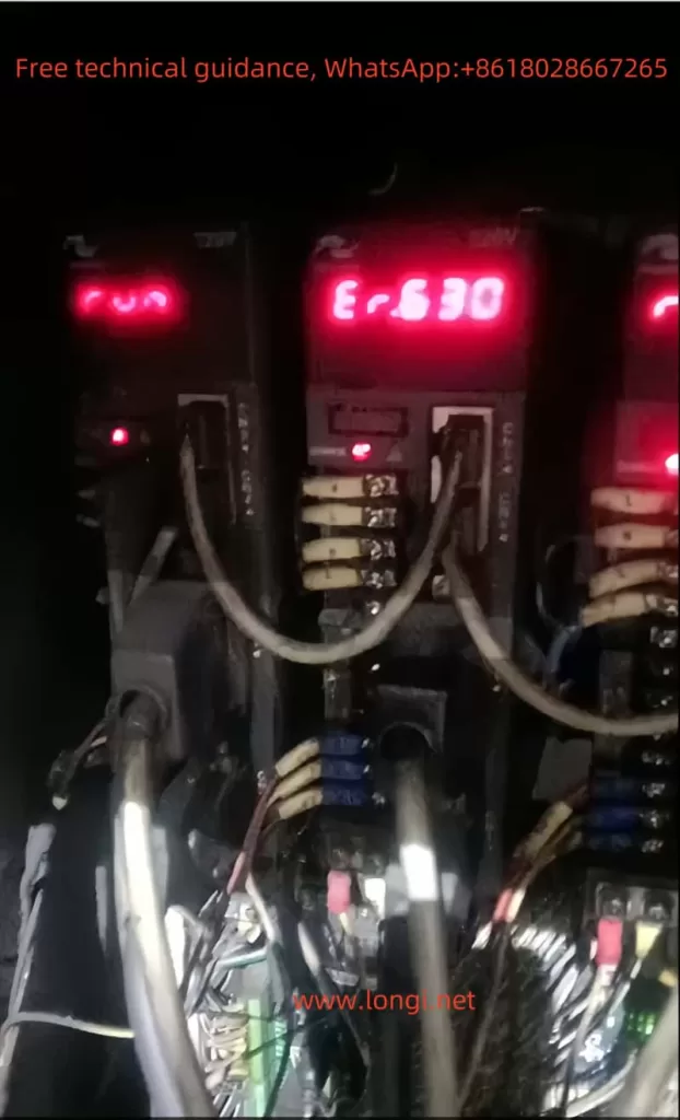
ERR13 Fault Handling Method
Common Causes of ERR13 Fault
- Overcurrent fault due to excessive load or short circuit.
- Motor parameters not properly set or identified.
- Insufficient cooling of the inverter or motor.
Handling Steps
- Check the Load: Ensure the load is within the inverter’s rated capacity and there are no short circuits or ground faults.
- Review Motor Parameters: Verify that the motor parameters (e.g., rated current, power) are correctly entered into the inverter.
- Check Cooling: Ensure adequate ventilation and cooling of both the inverter and the motor.
- Reset the Inverter: If the fault persists, try resetting the inverter by power cycling it or using the STOP/RES key.
- Consult the Manual: Refer to the user manual for more detailed troubleshooting steps and parameter adjustments.
By following these guidelines, users can effectively operate and troubleshoot the SHZK INVERTER ZK880 series, ensuring optimal performance and reliability.