Posted on Leave a comment

User Manual Guide for Inovance CS700 Series Crane-specific Inverter

I. Operation Panel Function Description and Basic Operations

Operation Panel Functionality

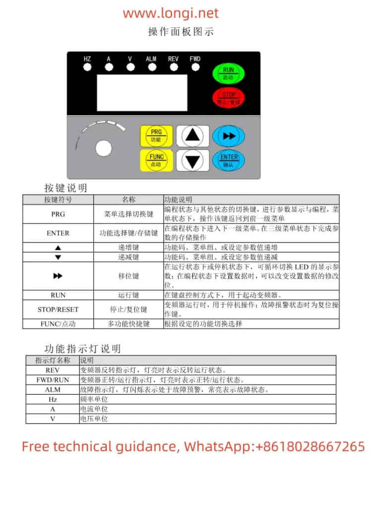
The Inovance CS700 series crane-specific inverter is equipped with an intuitive and user-friendly operation panel, which primarily includes the following buttons and indicators:

  • Buttons: Including PRG (programming key), ENTER (confirmation key), increment key (▲), decrement key (▼), shift key (◀/▶), RUN (run key), STOP/RES (stop/reset key), MF.K (multi-function key), QUICK (menu key), etc.
  • Indicators: Including RUN (run indicator), LOCAL/REMOT (command source indicator), FWD/REV (forward/reverse indicator), TUNE/TC (tuning/torque control/fault indicator), etc.

Basic Operations
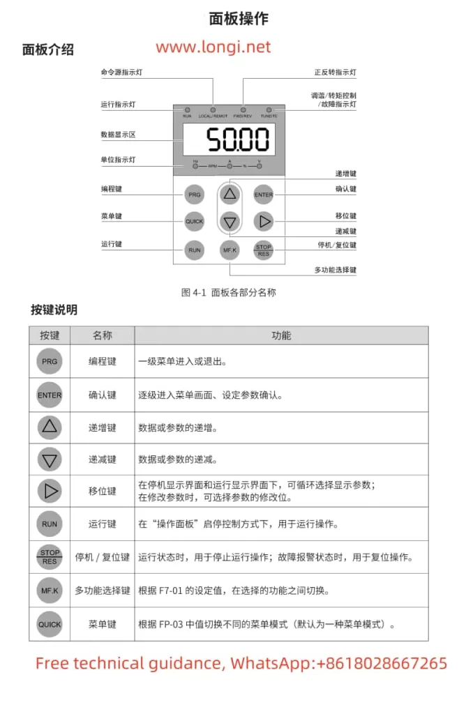
Function diagram of Huichuan CS700 crane dedicated VFD operation panel
  1. Start and Stop:
    • Press the RUN button to start the inverter, and the inverter run indicator (RUN) will light up.
    • Press the STOP/RES button to stop the inverter, and the inverter run indicator will go out.
  2. Speed Regulation:
    • Enter the programming mode by pressing the PRG button, adjust the target frequency using the increment key (▲) and decrement key (▼), and then press the ENTER button to confirm.

Password Setting and Removal

  • Password Setting: Set the password for all function parameters through parameter AF.00, the password for the second-level menu through parameter bF.00, and the password for the third-level menu through parameter FF.00.
  • Password Removal: Set the password parameter to 0 to remove the password protection.

Parameter Initialization

  • Press the PRG button to enter the programming mode, select parameter AF.01 (restore factory parameters for the first-level menu), bF.01 (restore factory parameters for the second-level menu), or FF.10 (restore factory parameters for the third-level menu), and press the ENTER button to confirm.
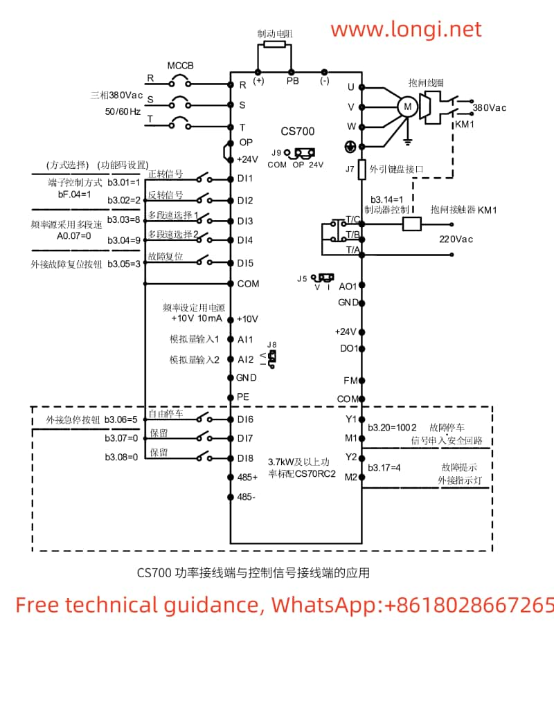
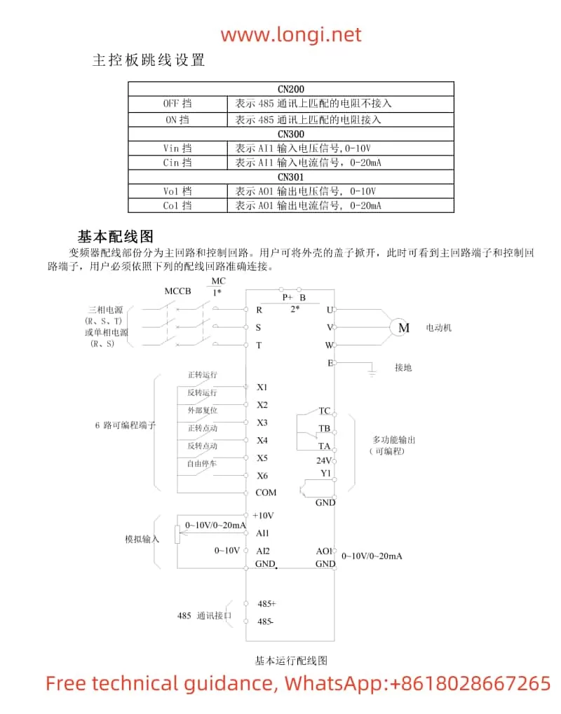
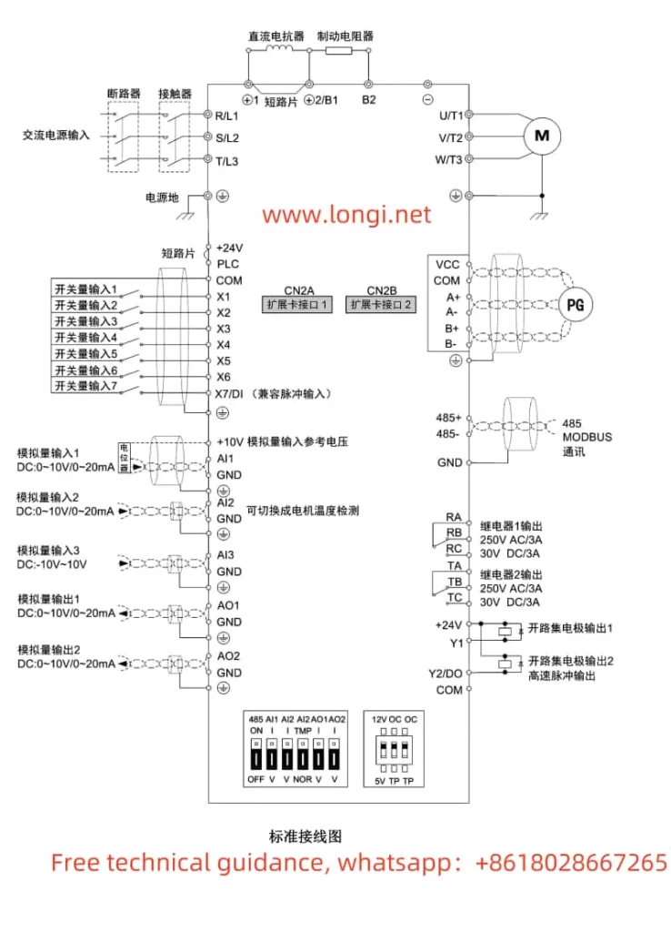
Typical wiring diagram of Huichuan CS700 crane specific VFD

II. Crane Mode and PG Encoder Feedback Settings

Crane Mode Selection

The CS700 series inverter supports multiple crane modes, generally achieved through the multi-speed function. The specific setting steps are as follows:

  1. Enter the programming mode, select parameter A0.07, and set it to 0 to choose multi-speed as the frequency source.
  2. Set parameters b3.01~b3.05 to define DI1~DI5 as multi-speed selections 1~5, respectively.
  3. Set the corresponding frequency for each speed in parameters b5.00~b5.07.

PG Encoder Feedback Settings

If PG encoder feedback is selected, the following settings and wiring are required:

  1. Parameter Settings:
    • Enter the programming mode, select parameter b1.00, and set it to 1 to choose encoder vector control (closed-loop control mode).
    • Set parameters b2.00 (encoder lines) and b2.01 (encoder type) according to the actual encoder type used.
  2. Wiring:
    • Connect the encoder signal wires to the PG card interface of the inverter, with specific wiring reference to the wiring diagram in the manual.

III. Fault Code Meanings and Solutions

The CS700 series inverter provides a wealth of fault codes to help users quickly locate and resolve issues. Below are some common fault codes, their meanings, and solutions:

  1. Er02: Acceleration Overcurrent
    • Meaning: Grounding or short circuit in the inverter output circuit, or too short acceleration time, etc.
    • Solution: Check the peripheral circuit and eliminate grounding or short circuit faults; increase the acceleration time.
  2. Er03: Deceleration Overcurrent
    • Meaning: Grounding or short circuit in the inverter output circuit, or too short deceleration time, etc.
    • Solution: Check the peripheral circuit and eliminate grounding or short circuit faults; increase the deceleration time.
  3. Er04: Constant Speed Overcurrent
    • Meaning: Grounding or short circuit in the inverter output circuit, or low voltage, etc.
    • Solution: Check the peripheral circuit and eliminate grounding or short circuit faults; adjust the voltage to the normal range.
  4. Er05: Acceleration Overvoltage
    • Meaning: High input voltage, or external force dragging the motor during acceleration, etc.
    • Solution: Adjust the voltage to the normal range; eliminate external force dragging or install braking resistors.
  5. Er08: Control Power Supply Fault
    • Meaning: Input voltage is not within the specified range.
    • Solution: Adjust the voltage to meet the specified requirements.
  6. Er10: Inverter Overload
    • Meaning: Excessive load or motor stall, or undersized inverter selection, etc.
    • Solution: Reduce the load and check the motor and machinery; select an inverter with a larger power rating.
  7. Er11: Motor Overload
    • Meaning: Improper setting of motor protection parameters, or excessive load, etc.
    • Solution: Set the motor protection parameters correctly; reduce the load.
  8. Er12: Input Phase Loss
    • Meaning: Abnormal three-phase input power.
    • Solution: Check and eliminate issues in the peripheral circuitry.
  9. Er14: Module Overheat
    • Meaning: High ambient temperature or blocked air duct, etc.
    • Solution: Lower the ambient temperature and clean the air duct.
  10. Er37: Frequency Direction Anomaly
    • Meaning: The direction of the given running frequency is opposite to that of the motor feedback frequency.
    • Solution: Check the motor parameter settings and adjust parameter bC.02 if necessary.
  11. Er41: Loose Brake Fault
    • Meaning: Error in the input of the loose brake feedback signal.
    • Solution: Check the brake circuit wiring and the function selection of the control panel’s loose brake feedback input point.
  12. Er42: Holding Brake Fault
    • Meaning: Error in the input of the holding brake feedback signal.
    • Solution: Check the brake circuit wiring and the function selection of the control panel’s holding brake feedback input point.

IV. Conclusion

The Inovance CS700 series crane-specific inverter is a powerful and easy-to-operate inverter dedicated to crane equipment. Through this guide, users can quickly master the basic functions of the operation panel, the setting method for crane modes, the configuration steps for PG encoder feedback, and solutions to common fault codes. It is hoped that this user guide will help users better use and maintain the CS700 series inverters, improving the work efficiency and safety of crane equipment.

Posted on Leave a comment

HARS Inverter HS720 Series Operation Method and PID Control Implementation for a Single Pump

I. Operation Method of the HARS Inverter HS720 Series

The HARS Inverter HS720 Series is a high-performance current vector inverter with a wide range of applications. This article will provide a detailed introduction on how to set the inverter to start via the operation panel and use the panel potentiometer to set the frequency, enabling direct start/stop control via the operation panel and speed regulation through the panel potentiometer.

Function diagram of HARS INVERTER HS720 series operation panel

1.1 Setting Operation Panel Startup and Panel Potentiometer Frequency Setting

First, ensure that the inverter’s power supply is correctly connected, and all safety measures are in place. Next, follow these steps to configure the settings:

  1. Enter Programming Mode: Press the PRG key on the inverter’s operation panel to enter the programming menu.
  2. Set Run Command Selection: In the programming menu, find the F0.02 parameter and set it to 0. This selects the keyboard operation mode for run commands.
  3. Set Main Frequency Source A Selection: Continue to find the F0.03 parameter and set it to 1. This indicates that the keyboard potentiometer is selected as the frequency setting method.
  4. Save and Exit: After completing the settings, press the SET key to save the parameters and press the PRG key to exit programming mode.

Now, you can start and stop the inverter using the RUN and STOP/RESET keys on the operation panel, and adjust the output frequency by rotating the panel potentiometer to achieve speed regulation.

II. Restoring Factory Default Settings for the Inverter

During the use of the inverter, it may be necessary to restore the parameters to their factory default values for reconfiguration or troubleshooting. The HARS Inverter HS720 Series provides a function to restore factory default settings, with the following steps:

  1. Enter Programming Mode: Press the PRG key to enter the programming menu.
  2. Select Data Initialization: Find the F0.17 parameter and set it to 2. This selects restoring factory default settings (excluding motor parameters and F8 group parameters).
  3. Confirm and Wait: Press the SET key to confirm the selection, and the inverter will begin the process of restoring factory default settings. Please wait patiently until initialization is complete.
  4. Exit Programming Mode: After initialization is complete, the inverter will automatically exit programming mode and restore to factory default settings.
HARS INVERTER HS720 Series Basic Wiring Diagram

III. PID Control Implementation for a Single Pump

In a constant pressure water supply system, the PID function within the inverter can be used to achieve constant pressure control of the water pump motor. The PID (Proportional-Integral-Derivative) controller is a commonly used feedback control system that continuously adjusts the output signal to make the system output reach and maintain the set value.

3.1 Introduction to PID Principles

The PID controller adjusts the output signal by calculating the deviation between the set value and the actual feedback value, based on three components: proportional (P), integral (I), and derivative (D). Among them:

  • Proportional (P): Adjusts the output based on the proportion of the deviation. The larger the deviation, the greater the output adjustment.
  • Integral (I): Integrates the deviation to eliminate the system’s static error.
  • Derivative (D): Adjusts the output based on the rate of change of the deviation to predict future deviations and make adjustments in advance.

In a constant pressure water supply system, the derivative component is usually not required, so the derivative gain can be set to 0.

3.2 Wiring and Parameter Settings

To achieve constant pressure water supply control using the panel potentiometer as the PID setpoint and port AI1 as the PID feedback value, follow these wiring and parameter setting steps:

Wiring Steps:

  1. Setpoint Wiring: Connect the output terminal of the panel potentiometer to the AI1 terminal of the inverter (as the PID setpoint input).
  2. Feedback Wiring: Connect the output signal of the pressure sensor (typically 420mA or 010V) to the AI2 terminal of the inverter (as the PID feedback input).
  3. Ensure Grounding: Ensure that all signal wires are properly grounded to avoid interference.

Parameter Setting Steps:

  1. Enter Programming Mode: Press the PRG key to enter the programming menu.
  2. Enable PID Function: Find the FA.00 parameter and set it to 1 to enable reverse-acting PID control.
  3. Set PID Setpoint Selection: Set the FA.01 parameter to 1, indicating that the keyboard potentiometer is selected as the PID setpoint.
  4. Set PID Feedback Selection: Set the FA.02 parameter to 2, indicating that AI1 is selected as the PID feedback input (Note: This differs slightly from the wiring as AI1 is already used as the setpoint input. In actual operation, ensure that the feedback value is input to the correct terminal, such as AI2).
  5. Adjust PID Parameters: Adjust PID parameters such as FA.09 (proportional gain), FA.10 (integral time), and FA.11 (derivative time) according to system requirements. In a constant pressure water supply system, the derivative time is typically set to 0.
  6. Save and Exit: After completing the settings, press the SET key to save the parameters and press the PRG key to exit programming mode.

Now, the inverter will automatically adjust the speed of the water pump motor based on the set PID parameters and the feedback signal from the pressure sensor to achieve constant pressure water supply control.

IV. Conclusion

The HARS Inverter HS720 Series is a powerful and easy-to-operate high-performance inverter. Through this article, you have learned how to set it to start via the operation panel and use the panel potentiometer to set the frequency, how to restore factory default settings, and how to use the PID function to achieve constant pressure water supply control for a single pump. In actual applications, you can further adjust and optimize the inverter’s parameter settings according to specific needs to achieve the best control effect.

Posted on Leave a comment

User Manual Guide for Yaskawa Inverter A1000 Series

The Yaskawa Inverter A1000 Series is a high-performance vector control inverter widely used in various industrial control applications. This document aims to provide users with a detailed guide, covering the function explanation of the operation panel, password setting and cancellation, parameter initialization settings, external terminal start/stop and potentiometer speed adjustment settings, as well as common fault codes and troubleshooting methods.

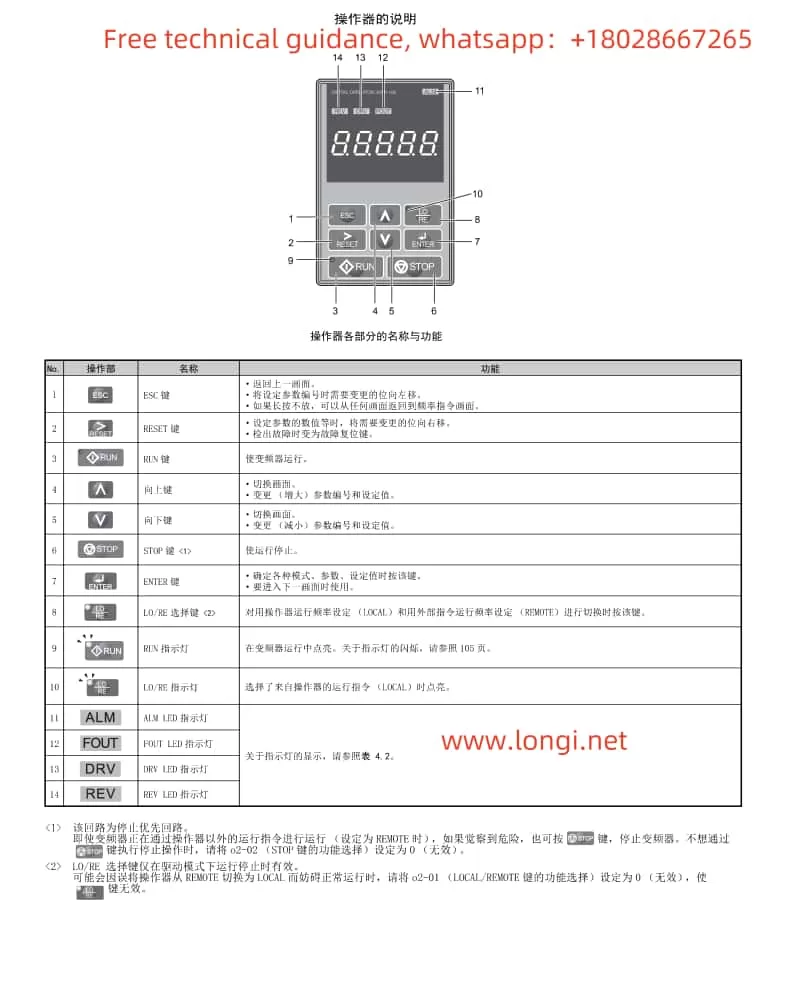
Function Description Diagram of Yaskawa A1000 Series Inverter Operation Panel

I. Function Explanation of the Operation Panel (Operator)

The operation panel of the Yaskawa Inverter A1000 Series integrates multiple functions, facilitating user parameter settings and status monitoring. Below are the main functions of the operation panel:

  1. Display and Operation: The operation panel features an LED display and multiple operation keys, including the “LOCAL/REMOTE” key and the “STOP” key, allowing users to perform local or remote operations and stop the inverter.
  2. Password Setting and Cancellation:
    • Password Setting: Enter the parameter setting mode and set the password by configuring A1-04 (Password) and A1-05 (Password Setting). The specific steps are: First, press the “ESC” key to enter the parameter setting mode, then select A1-05 and input the password value, and finally press the “ENTER” key to confirm.
    • Password Cancellation: To cancel the set password, set A1-04 (Password) to the same value as A1-05 (Password Setting), then re-enter the parameter setting mode and set both A1-04 and A1-05 to 0.
  3. Parameter Initialization Settings: Set A1-03 (Initialization) to choose different initialization methods. Common options include:
    • 1110: Initializes based on user settings, restoring parameters to user-saved values.
    • 2220: Initializes for 2-wire sequential control, restoring factory settings for 2-wire sequential control.
    • 3330: Initializes for 3-wire sequential control, restoring factory settings for 3-wire sequential control.
    • 5550: Resets oPE04, used for parameter reset after replacing the detachable terminal block.

II. External Terminal Start/Stop and Potentiometer Speed Adjustment Settings

To enable external terminal start/stop and potentiometer speed adjustment functions for the Yaskawa Inverter A1000 Series, the following parameter and wiring settings are required:

  1. Parameter Settings:
    • Set b1-01 (Run Command Selection 1) to 2, selecting external terminal run commands.
    • Set b1-02 (Run Command Selection 2) to 0, selecting the 2-wire sequential control mode for forward/stop and reverse/stop (or select other modes as needed).
    • Set H1-01 and H1-02 to 40 and 41, respectively, assigning the S1 and S2 terminals as input for forward and reverse run commands.
  2. Wiring Settings:
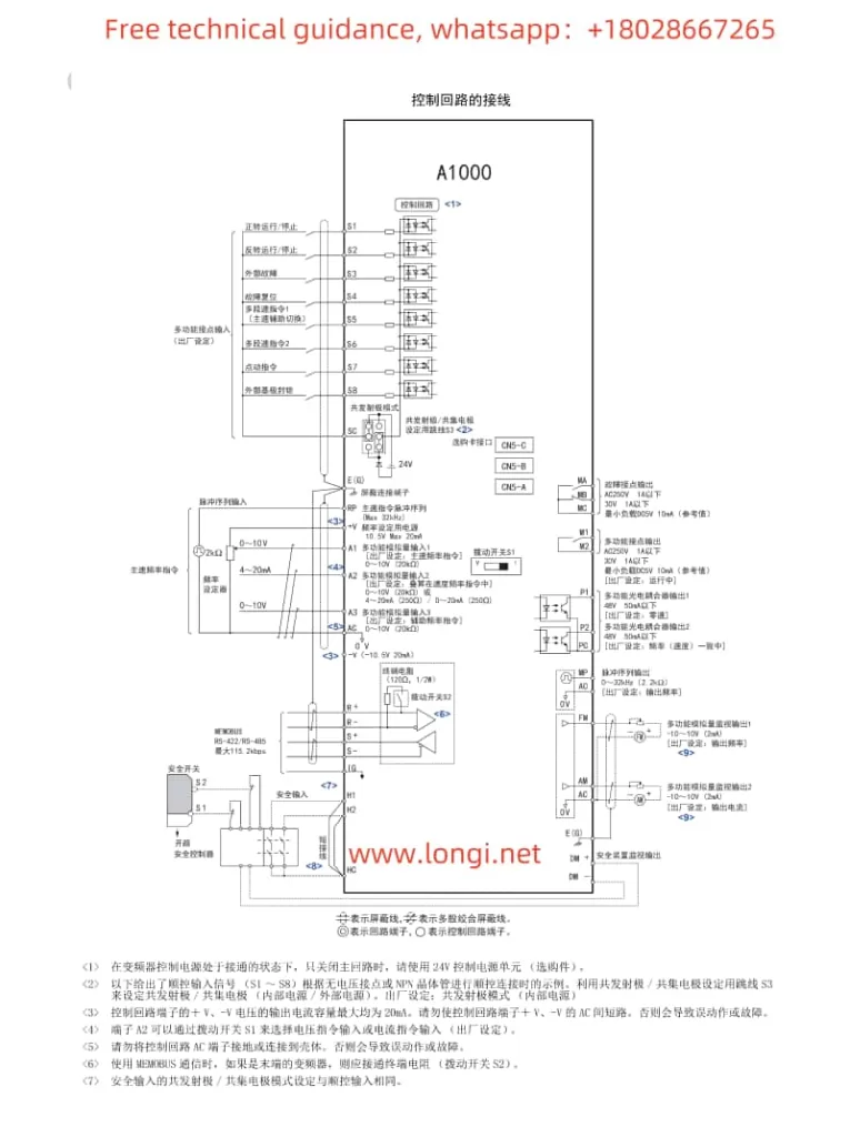
    • Connect the external start/stop buttons to the S1 and S2 terminals.
    • Connect the center tap of the potentiometer to the common terminal of the inverter (e.g., 0V), and connect the ends of the potentiometer to the analog input terminals of the inverter (e.g., A1 and +V or -V) to achieve potentiometer speed adjustment.
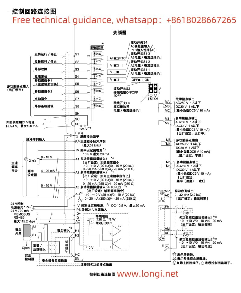
Yaskawa A1000 series inverter control circuit wiring diagram

III. Common Fault Codes and Troubleshooting Methods

The Yaskawa Inverter A1000 Series may encounter various faults during operation. Below are some common fault codes, their meanings, and troubleshooting methods:

  1. oL1 (Motor Overload):
    • Meaning: The motor current exceeds the rated value, triggering the overload protection.
    • Troubleshooting: Check if the motor load is too heavy, adjust the load or increase the motor capacity; check the motor wiring for correctness to avoid line-to-line shorts; check the inverter parameter settings to ensure the motor parameters match the actual motor.
  2. Uv1 (Main Circuit Undervoltage):
    • Meaning: The main circuit DC voltage is lower than the set value.
    • Troubleshooting: Check if the power supply voltage is stable and within the allowable range; check the power wiring for firmness to avoid poor contact; check if the internal capacitors of the inverter are aged or damaged.
  3. oH1 (Inverter Overheat):
    • Meaning: The internal temperature of the inverter is too high, triggering the overheat protection.
    • Troubleshooting: Check the installation environment of the inverter to ensure adequate ventilation; check if the inverter heat sink is clean and free of dust accumulation; check if the cooling fan is working properly and replace it if faulty.
  4. oPE03 (Improper Selection of Multi-function Input):
    • Meaning: There is a conflict or error in the function assignment of the multi-function input terminals.
    • Troubleshooting: Check the parameter settings of H1-01 to H1-08 to ensure the function assignment of each terminal is correct and without duplication; check if any unused terminals have been assigned functions mistakenly.
  5. Er-11 (Motor Speed Fault):
    • Meaning: During rotary self-learning, the motor speed is abnormal.
    • Troubleshooting: Check the connection between the motor and the inverter for correctness; check the wiring and settings of the PG (encoder); re-perform self-learning with the motor and mechanical system connected.

The above are only some common fault codes and their troubleshooting methods. In actual use, other faults may occur. Users should refer to the fault code table in the inverter user manual and take corresponding measures based on specific fault codes and meanings. Additionally, regular maintenance and inspection of the inverter are important means to prevent faults.

Posted on Leave a comment

User Manual for Yaskawa GA700 Series Inverte

I. Detailed Explanation of Operator Panel Functions

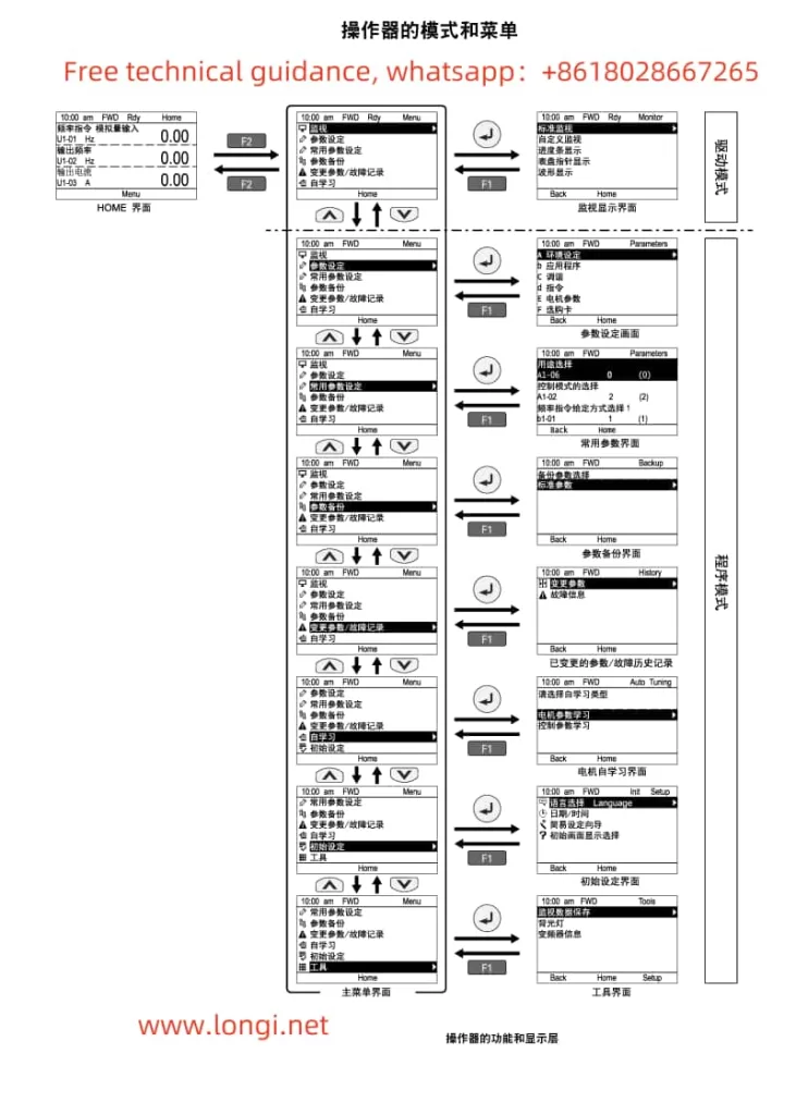
Mode and menu diagram of Yaskawa inverter GA700 operation panel

The operator panel of the Yaskawa GA700 Inverter serves as the primary interface for user interaction, providing a wealth of functions and setting options. Below are the main functions and operation instructions for the operator panel:

  1. Display and Setting Functions
    • Monitoring Display: The operator panel can display various status information of the inverter, such as frequency command, output frequency, current, voltage, etc. Users can select the desired monitoring item using the up, down, left, and right keys.
    • Parameter Settings: Through the operator panel, users can access and modify various inverter parameters to meet different application requirements. Press the “MENU” key to enter the menu, then use the up and down keys to select the desired parameter, and press the “ENTER” key to enter the parameter setting interface.
  2. Restoring Factory Default Parameters
    If it is necessary to restore the inverter parameters to their factory defaults, follow these steps:
    • Press the “MENU” key to enter the menu.
    • Use the up and down keys to select the “Tools” menu, then press the “ENTER” key to enter.
    • In the “Tools” menu, use the up and down keys to select the “Parameter Initialization” option, then press the “ENTER” key to enter.
    • Select “Factory Default Initialization” and press the “ENTER” key to confirm. The system will prompt for confirmation; press the “YES” key to initialize, and the inverter parameters will be restored to their factory defaults.
  3. Setting External Terminal Start
    External terminal start refers to controlling the start and stop of the inverter through external signals (such as buttons, switches, etc.). Follow these steps to set external terminal start:
    • Ensure that the external control circuit is correctly wired.
    • Enter the “Application” menu on the operator panel and select “Frequency Command Source 1” (b1-01).
    • Set b1-01 to “0”, indicating that the operator panel is used to input the run command. If external terminal start is desired, set it to “2” (indicating that the control circuit terminal is used to input the run command).
    • Set other related parameters as needed, such as the function selection for the external start terminal (H1-xx parameter).
Yaskawa inverter GA700 control circuit wiring

II. Settings for External Terminal Start and External Potentiometer Speed Control

  1. External Terminal Start Settings
    The settings for external terminal start include wiring and parameter settings:
    • Wiring Steps:
      • Connect one contact of the external start button or switch to the “RUN” terminal of the inverter (e.g., terminal S1).
      • Connect the other contact to the common terminal of the inverter (e.g., terminal CM).
    • Parameter Setting Steps:
      • Enter the “Application” menu on the operator panel and select “Frequency Command Source 1” (b1-01).
      • Set b1-01 to “2”, indicating that the control circuit terminal is used to input the run command.
      • Enter the “Multi-function Input Terminals” menu (H1-xx), select the corresponding terminal (e.g., H1-01), and set its function to “Run Command” (e.g., set value “1”).
  2. External Potentiometer Speed Control Settings
    External potentiometer speed control allows users to adjust the output frequency of the inverter by rotating the potentiometer, thereby controlling the motor speed.
    • Wiring Steps:
      • Connect the three terminals of the potentiometer to the “AI1” (Analog Input 1) terminal of the inverter, the common terminal (e.g., terminal CM), and ground (GND), respectively.
    • Parameter Setting Steps:
      • Enter the “Application” menu on the operator panel and select “Frequency Command Source 1” (b1-01).
      • Set b1-01 to “1”, indicating that analog input is used as the frequency command.
      • Enter the “Multi-function Analog Input” menu (H3-xx), select “Terminal A1 Function Selection” (H3-02), and set it to “Main Speed Frequency Command” (set value “0”).
      • Adjust “Terminal A1 Input Gain” (H3-03) and “Terminal A1 Input Offset” (H3-04) as needed to match the output range of the potentiometer and the frequency command range of the inverter.

III. Inverter Fault Codes and Handling Methods

When the Yaskawa GA700 Inverter encounters a fault, it will display the corresponding fault code. Below are some common fault codes, their meanings, and handling methods:

  1. oC (Overcurrent)
    • Meaning: The inverter output current exceeds the rated value.
    • Handling Method: Check if the motor load is too heavy, if there are short circuits or grounding faults, and adjust inverter parameters (such as acceleration/deceleration time, torque limit, etc.).
  2. oV (Overvoltage)
    • Meaning: The DC bus voltage of the inverter is too high.
    • Handling Method: Check if the input power supply is stable, if there are issues with the braking resistor (overheating or damage), and adjust inverter parameters (such as deceleration time, overvoltage suppression function, etc.).
  3. oH (Overheat)
    • Meaning: The internal temperature of the inverter is too high.
    • Handling Method: Check if the installation environment of the inverter is well-ventilated, if there is dust accumulation or blocked heat sinks, clean the heat sinks, and check if the cooling fan is working properly.
  4. FbL (PID Feedback Lost)
    • Meaning: The feedback signal is lost in PID control.
    • Handling Method: Check if the PID feedback loop is correctly wired, if the feedback sensor is working properly, and adjust PID control parameters.
  5. EF (External Fault)
    • Meaning: An external fault signal has been received.
    • Handling Method: Check if the external fault signal source is normal, resolve the external fault, and reset the inverter.

The above are only some common fault codes and their handling methods. In actual use, more fault codes may be encountered. Users should refer to the inverter’s technical manual to understand the meanings of various fault codes and the corresponding handling methods to ensure the normal operation of the inverter.

Through this introduction, users should now have a comprehensive understanding of the operator panel functions, settings for external terminal start and external potentiometer speed control, and fault code handling for the Yaskawa GA700 Inverter. In practical applications, users should set the inverter parameters reasonably based on specific application requirements and environmental conditions to ensure the safe and stable operation of the inverter.

Posted on Leave a comment

ABB AC Drive ACS880 Series Firmware Manual User Guide

Introduction

The ABB ACS880 series AC Drives represent a high-performance drive system widely utilized across various industrial applications. To ensure users can efficiently and safely operate this product, this document provides a comprehensive guide to the features and operations of the ACS880 series AC Drives, focusing on the operation panel (control pad), external control settings, and other key functionalities.


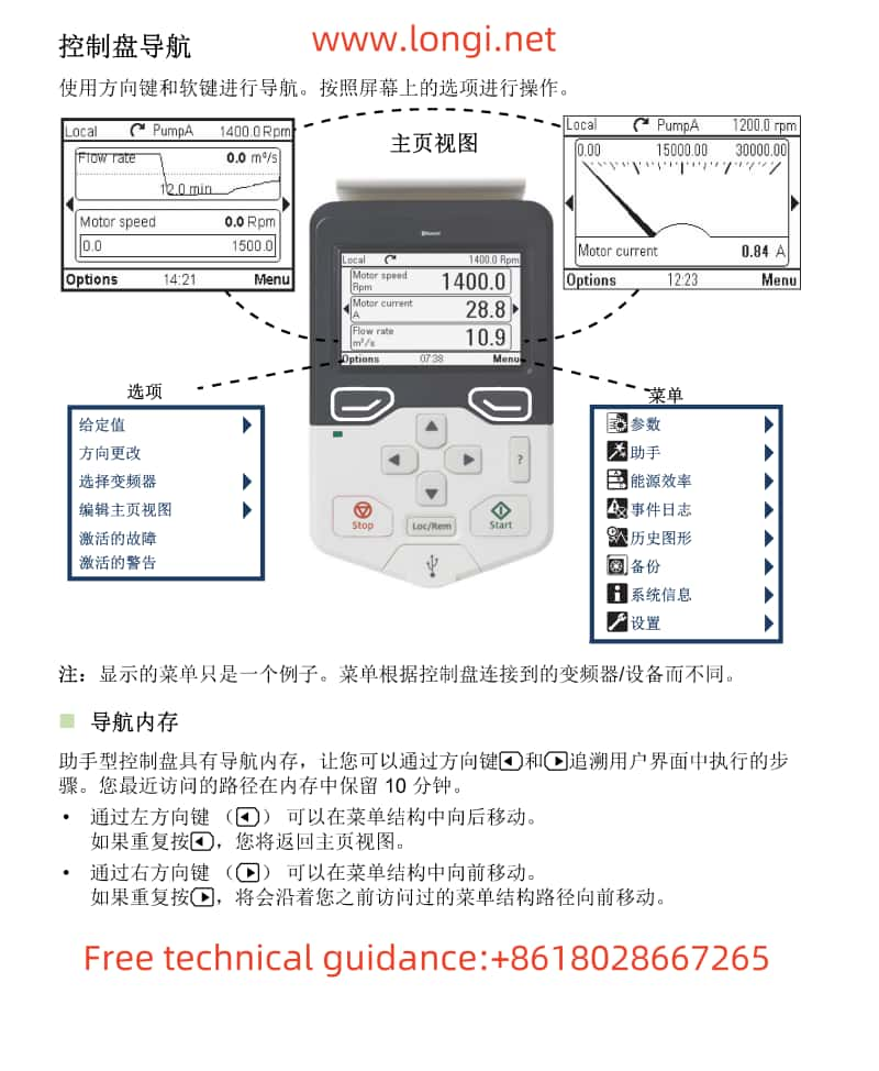
ACS-AP-x control panel function navigation diagram

Operation Panel (Control Pad) Functionality

Overview

The operation panel, also known as the control pad, serves as the primary interface for configuring and monitoring the ACS880 AC Drive. This section will detail the functions of the control pad, including how to reset the drive to factory settings, set a password, and remove a password.

Resetting to Factory Settings

To reset the ACS880 AC Drive to its factory settings using the control pad:

  1. Access the Main Menu: Navigate to the main menu on the control pad.
  2. Select Parameters: Locate and select the “Parameters” menu.
  3. Reset to Factory Defaults: Find the option to reset to factory defaults and confirm the action.

Note: Resetting to factory settings will erase all user-defined parameters and configurations. Ensure all necessary settings are backed up before proceeding.

Setting a Password

To protect your drive settings from unauthorized access, you can set a password on the control pad:

  1. Access the Parameters Menu: Navigate to the “Parameters” menu on the control pad.
  2. Locate the Password Setting: Find the parameter related to setting a password.
  3. Enter the Password: Follow the prompts to enter and confirm your desired password.
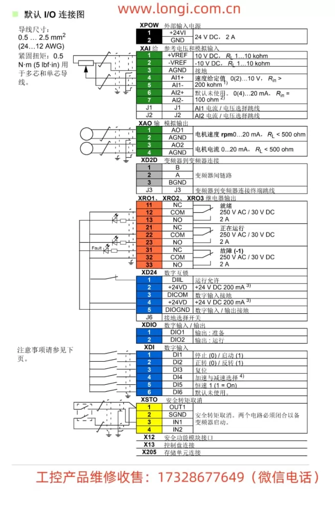
ACS880-01 default IO connection diagram

Removing a Password

If you need to remove a previously set password:

  1. Access the Parameters Menu: Navigate to the “Parameters” menu on the control pad.
  2. Locate the Password Removal Setting: Find the parameter related to removing the password.
  3. Enter the Current Password: You may be prompted to enter the current password to confirm the removal.
  4. Confirm Removal: Follow the prompts to confirm the password removal.

Setting Up External Control

Overview

External control allows you to start, stop, and adjust the speed of the ACS880 AC Drive via external signals rather than through the control pad. This section will guide you through the necessary wiring and steps to set up external control, including starting and stopping the drive and adjusting its speed via an external potentiometer.

Wiring for Start and Stop

To control the start and stop functions of the ACS880 AC Drive externally, you need to connect the appropriate terminals on the drive:

  1. Locate the Control Terminals: Identify the terminals labeled for start and stop control on the drive.
  2. Wire the Terminals: Connect your external control devices (e.g., pushbuttons, relays) to these terminals according to the required logic (e.g., normally open, normally closed).

Note: Ensure proper polarity and isolation to prevent short circuits and electrical hazards.

Adjusting Speed via External Potentiometer

To adjust the speed of the ACS880 AC Drive using an external potentiometer:

  1. Connect the Potentiometer: Use a suitable potentiometer and connect its terminals to the analog input terminals on the drive designated for speed control.
  2. Configure the Analog Input: Navigate to the “Parameters” menu on the control pad and configure the analog input to accept speed commands from the potentiometer.
  3. Calibrate the Potentiometer: Adjust the potentiometer’s range to match the desired speed range of the drive.

Note: Refer to the drive’s manual for specific parameter settings related to analog input and speed control.


Conclusion

This guide provides a comprehensive overview of the essential functionalities of the ABB ACS880 series AC Drives, focusing on the operation panel and external control settings. By following the steps outlined in this guide, users can efficiently configure and operate their drives, ensuring optimal performance and safety in various industrial applications. Always refer to the drive’s manual for detailed parameter settings and additional features.

Posted on Leave a comment

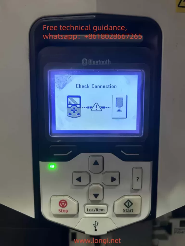
ABB AC Drive ACS880 Series “Check Connection” Fault Analysis and Solution

In the field of industrial automation, ABB’s ACS880 series AC drives are highly regarded for their efficiency, reliability, and ease of maintenance. However, as with any complex electrical equipment, issues can arise. One such issue, similar to the A5001 (Drive Not Responding) fault seen in the ACS510 and ACS550 series, is the “Check Connection” fault in the ACS880 series. This article aims to analyze the meaning and provide solutions for the “Check Connection” fault in the ABB ACS880 series AC drives.

Meaning of “Check Connection” Fault

The “Check Connection” fault in the ABB ACS880 series AC drives typically indicates a problem with the communication or connection between the main control board (or control card) and the operator interface or other connected devices. This fault can occur due to various reasons, such as loose cables, faulty connectors, or communication settings issues.

When this fault occurs, the AC drive may not respond to commands from the operator interface or may exhibit abnormal behavior. It is essential to diagnose and resolve this fault promptly to ensure the smooth operation of the drive and the overall industrial process.

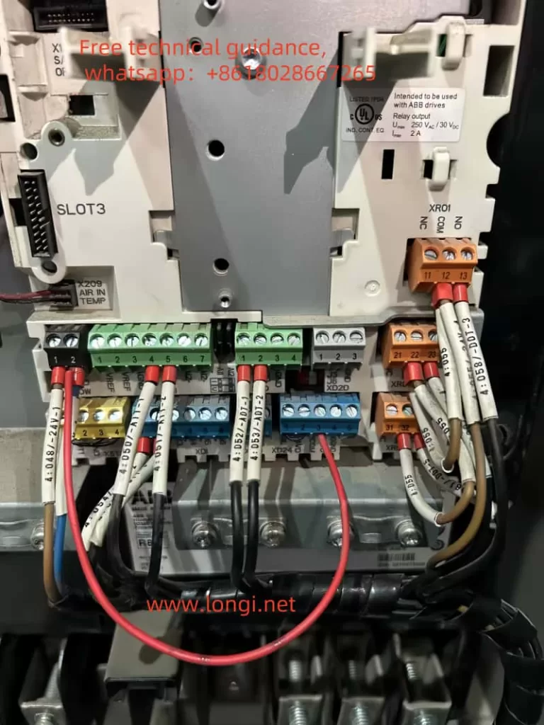
ACS880 on-site wiring diagram

Fault Analysis

Possible Causes

  1. Loose or Faulty Cables: Over time, cables can become loose or damaged, disrupting the communication between the control board and other components.
  2. Faulty Connectors: Connectors that have seen extensive use or improper handling can wear out, causing intermittent or complete loss of communication.
  3. Communication Settings: Incorrect communication settings or protocol mismatches can prevent the control board from communicating properly with other devices.
  4. Control Board Issues: In rare cases, the control board itself may have hardware or software issues that affect its ability to communicate.
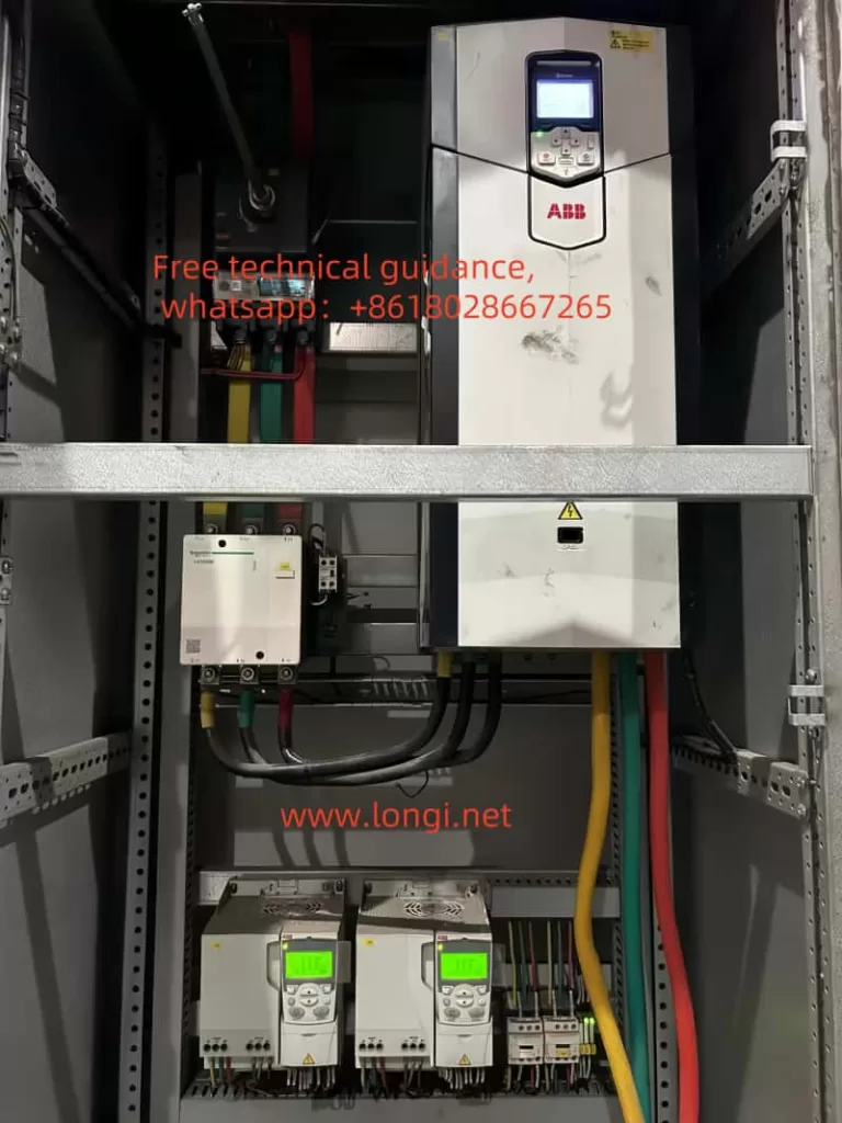
 AC Drive ACS880

Diagnosis

  1. Check Cable Connections: Visually inspect all cables connecting the control board to the operator interface and other devices. Ensure that the cables are securely fastened and free from damage.
  2. Inspect Connectors: Carefully examine the connectors on both ends of the cables. Look for signs of wear, corrosion, or damage that could affect the connection.
  3. Verify Communication Settings: Compare the communication settings in the AC drive with those required by the connected devices. Ensure that the correct protocol, baud rate, and other parameters are configured.
  4. Check Control Board Status: Use the drive’s diagnostic tools to check the status of the control board. Look for any error codes or warnings that may indicate a hardware or software issue.
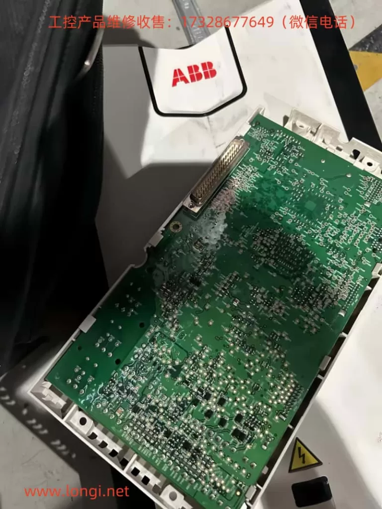
 AC Drive control card

Solution Methods

Step-by-Step Solutions

  1. Tighten or Replace Cables: If any cables are found to be loose or damaged, tighten them securely or replace them with new cables. Ensure that all connections are properly seated and free from debris.
  2. Replace Faulty Connectors: If connectors are found to be faulty, replace them with new connectors. Ensure that the new connectors are compatible with the existing cables and devices.
  3. Adjust Communication Settings: If communication settings are found to be incorrect, adjust them to match the requirements of the connected devices. Refer to the user manual for guidance on setting up communication parameters.
  4. Contact Technical Support: If the fault persists after checking cables, connectors, and communication settings, it may be necessary to contact ABB’s technical support for further assistance. The support team can provide additional diagnostics and recommend repair or replacement options if necessary.
 AC Drive check connection fault

Conclusion

The “Check Connection” fault in the ABB ACS880 series AC drives can be a frustrating issue, but it can be resolved through systematic diagnosis and targeted solutions. By carefully checking cable connections, inspecting connectors, verifying communication settings, and seeking assistance from technical support when needed, users can ensure that their AC drives remain operational and reliable. Proper maintenance and troubleshooting practices are key to maximizing the lifespan and performance of ABB ACS880 series AC drives in industrial applications.

Posted on Leave a comment

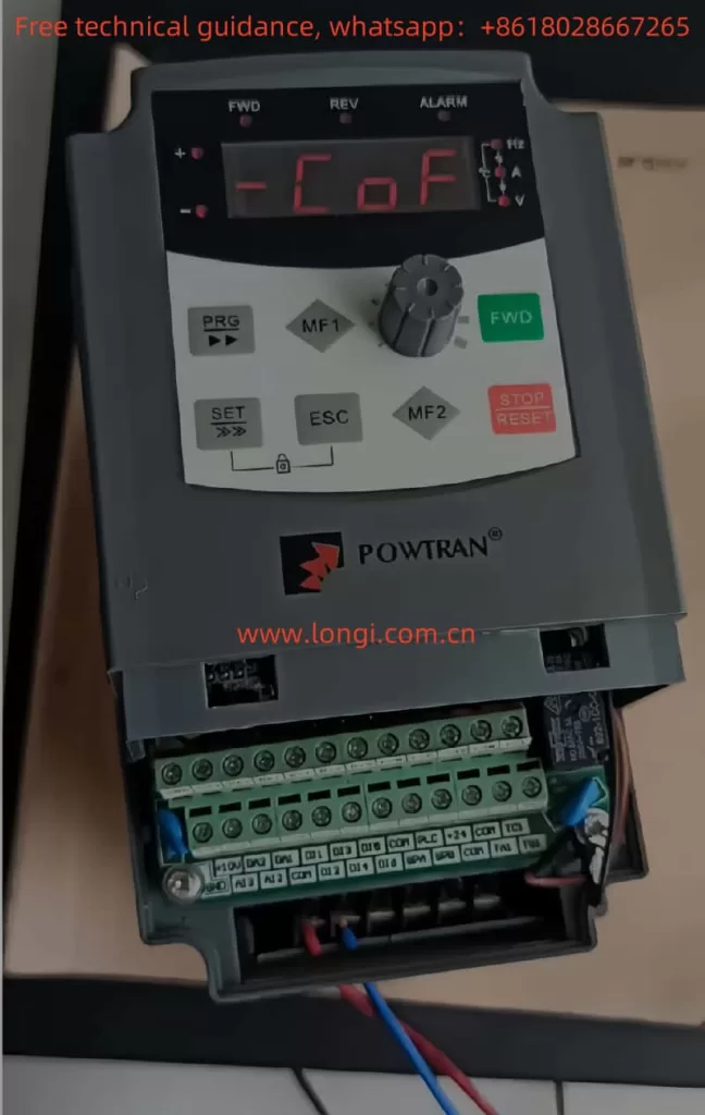
Usage Instructions and Troubleshooting of COF Fault in Powtran PI8600 Series Inverter

I. Usage Instructions for Powtran PI8600 Series Inverter

1. Panel Operation Setup

The panel operation of the Powtran PI8600 series inverters is straightforward. Here’s how to set up panel start, panel speed regulation, restore factory settings, set passwords, and remove passwords:

Panel Start and Speed Regulation:

  1. Entering Parameter Setting Mode:
    • Press the PRG button to enter the parameter group query state.
    • Use the potentiometer to switch to the F00-63 basic function group.
    • Press the PRG button again to enter the parameter query state within the F00-63 group.
    • Switch to F02 (Frequency Main Setting Mode) using the potentiometer.
    • Press the PRG button to enter the parameter modification state for F02.
    • Set F02 to 4 (Keyboard Potentiometer Given) using the potentiometer and SET button.
  2. Adjusting Speed:
    • Rotate the potentiometer on the panel to adjust the set frequency in real-time, which will also adjust the motor speed.

Restoring Factory Settings:

  1. In the monitoring state, press the PRG button to enter the parameter group query state.
  2. Use the potentiometer to switch to the y00-23 system function group.
  3. Press the PRG button to enter the parameter query state within this group.
  4. Switch to y00 (Reset System Parameters) using the potentiometer.
  5. Press the PRG button to enter the parameter modification state.
  6. Set the parameter to 5 to reset the system parameters to factory defaults using the potentiometer and SET button.
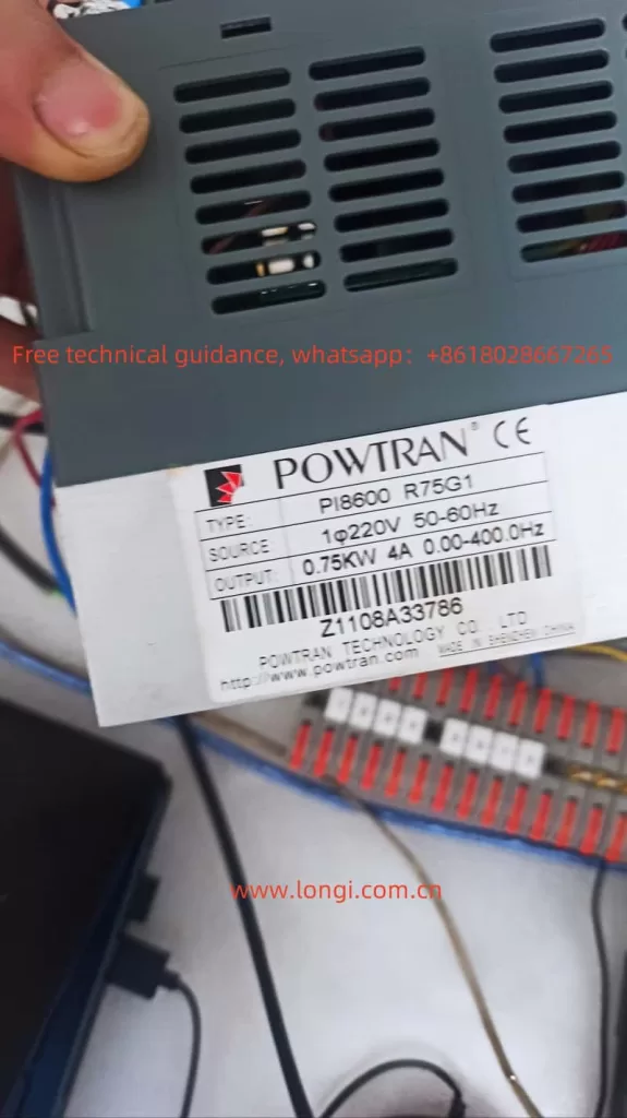
POWTRAN Inverter PI8600

Setting and Removing Passwords:

  1. Setting a Password:
    • Enter the system function group (y00-23) as described above.
    • Switch to y15 (User Decode Input) to set the password.
    • Enter the desired password using the potentiometer and SET button.
  2. Removing a Password:
    • Again, enter the system function group.
    • Switch to y16 (User Password Input).
    • Enter the current password followed by the new password (all zeros to remove the password) using the potentiometer and SET button.
2. Fault Code Enumeration and Analysis
FUALT COF

Fault Code COF – Communication Failure:

Symptoms:

  • The inverter fails to communicate properly with external devices or the control panel.

Possible Causes:

  1. Poor connection at the keyboard interface or control board.
  2. Faulty keyboard cable or crystal connector.
  3. Damaged control board or keyboard hardware.
  4. Excessive length of the keyboard cable causing interference.

Solutions:

  1. Check and tighten all connections at the keyboard interface and control board.
  2. Replace the keyboard cable or crystal connector if damaged.
  3. Inspect the control board and keyboard for any signs of damage. Replace if necessary.
  4. If using a long keyboard cable, consider using a shielded cable or reducing the cable length to minimize interference.

Other Common Fault Codes:

  • OC: Overcurrent. Check the motor and cable connections, and ensure the motor is not overloaded.
  • OU: Overvoltage. Verify the input voltage and consider installing a voltage stabilizer.
  • LU: Undervoltage. Check the power supply and ensure it meets the inverter’s voltage requirements.
  • OL: Overload. Reduce the load on the motor or adjust the overload protection parameters.

By following the above instructions, users can effectively operate the Powtran PI8600 series inverters, troubleshoot common issues, and maintain optimal performance.

Posted on Leave a comment

Powtran Inverter PI500 Series Operation Methods and ERR07 Fault Handling

I. Operation Methods for Powtran Inverter PI500 Series

1. Panel Start and Stop

The Powtran Inverter PI500 series features an easy-to-use operation panel, allowing users to start and stop the inverter via panel buttons. Specific steps are as follows:

  • Start: Press the “Run” button on the operation panel to start the inverter. In keyboard operation mode, this button is used to initiate running.
  • Stop: Press the “Stop/Reset” button on the operation panel to stop the inverter. In keyboard operation mode, this button is used to halt running; in fault alarm states, it can be used for reset operations.
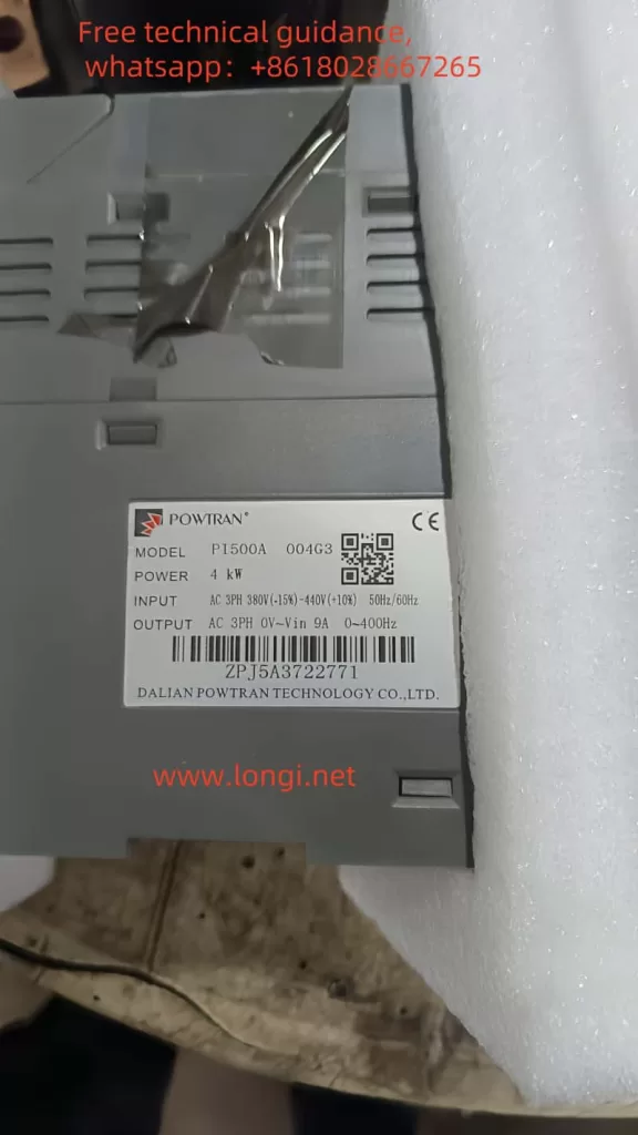
powtran inverter PI500 series

2. Debugging Steps

Proper debugging of the inverter is crucial to ensure its normal operation. The following is a general debugging process:

  1. Check Connections: Ensure all power and motor cable connections are correct and secure.
  2. Set Parameters: Configure various inverter parameters, such as control mode, acceleration and deceleration times, frequency source, etc., via the operation panel or remote communication.
  3. Motor Parameter Self-Learning: In vector control mode, motor parameter self-learning is required to ensure accurate motor control by the inverter.
  4. Jog Operation: Perform a jog operation to observe whether the motor’s rotation direction is correct. If abnormal, adjust the motor wiring phase sequence.
  5. Actual Operation: After confirming everything is correct, conduct an actual operation test to observe whether the inverter’s output frequency, current, voltage, and other parameters are normal.
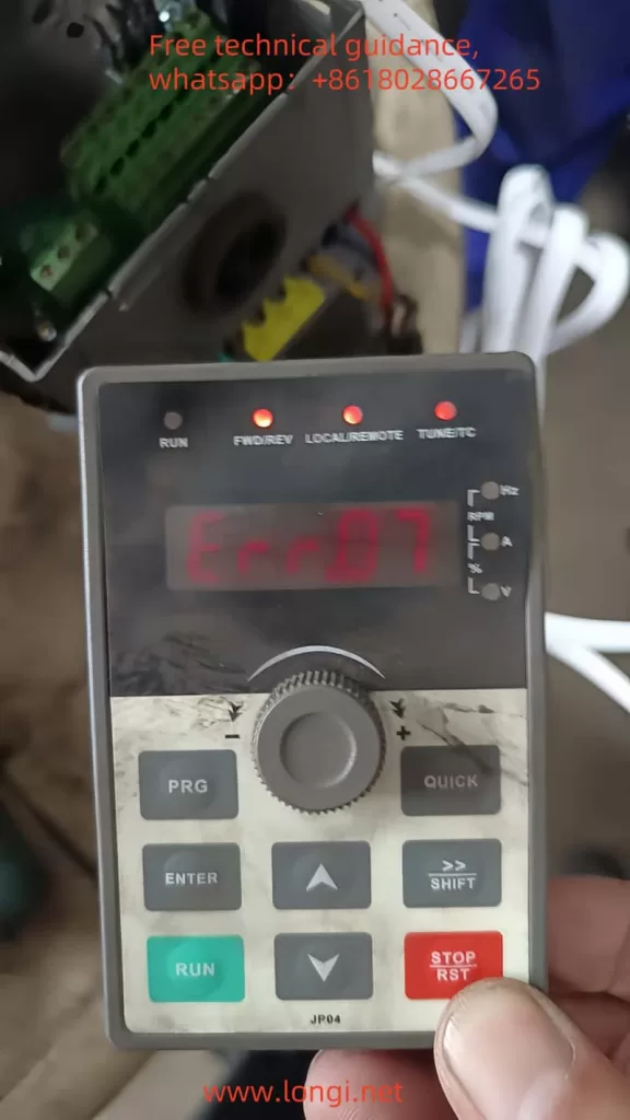
fault err.07 of powtran inverter

II. Inverter Fault Codes and Meanings

The Powtran Inverter PI500 series provides extensive fault codes to help users quickly locate issues. Here are some common fault codes and their meanings:

  • Err.01: Inverter unit protection, possibly caused by output circuit short circuit, module overheating, etc.
  • Err.02: Acceleration overcurrent, possibly caused by too short acceleration time, low voltage, etc.
  • Err.03: Deceleration overcurrent, possibly caused by too short deceleration time, sudden load changes, etc.
  • Err.04: Constant speed overcurrent, possibly caused by excessive load, motor stall, etc.
  • Err.05: Acceleration overvoltage, possibly caused by lack of braking unit, high input voltage, etc.
  • Err.07: Constant speed overvoltage, possibly caused by external force dragging the motor during operation, high input voltage, etc.

III. ERR07 Fault Analysis

The Err.07 fault code indicates constant speed overvoltage, meaning the inverter detects excessively high output voltage during constant speed operation. Possible causes include:

  1. High Input Voltage: When the input voltage exceeds the rated voltage range of the inverter, it may lead to excessively high output voltage.
  2. External Force Dragging the Motor: During constant speed operation, if the motor is dragged to rotate by an external force, it may cause the inverter’s output voltage to rise.
  3. Braking Unit Failure: If the inverter is not equipped with a braking unit or the braking unit fails, it may not effectively dissipate the motor’s regenerative energy during deceleration, resulting in voltage rise.

IV. Solutions for ERR07 Fault

1. Reset or Adjust Inverter Parameters

  • Check Input Voltage: Ensure the input voltage is within the rated voltage range of the inverter. If the input voltage is too high, measures must be taken to reduce it.
  • Check External Force Dragging: Eliminate the possibility of external force dragging the motor and ensure the motor operates in a free state.
  • Check Braking Unit: If the inverter is not equipped with a braking unit, it should be installed as per actual needs; if the braking unit fails, it should be promptly replaced.
  • Adjust Parameters: Adjust relevant inverter parameters based on actual conditions, such as acceleration and deceleration times, overvoltage protection thresholds, etc.

2. Replace Boards or Circuits

If the Err.07 fault cannot be resolved after the above adjustments, it may be necessary to replace internal boards or circuits of the inverter. Specific steps are as follows:

  1. Power Off: First, disconnect the inverter’s power supply to ensure safety.
  2. Disassemble the Enclosure: Use appropriate tools to disassemble the inverter’s enclosure to expose the internal circuitry.
  3. Locate Faulty Components: Based on the fault code and circuit diagram, locate the potentially faulty board or circuit.
  4. Replace Components: Remove the faulty board or circuit and replace it with a new one. Be careful not to damage other components during the replacement process.
  5. Assemble the Enclosure: After replacement, reinstall the inverter’s enclosure.
  6. Power On and Test: Power on the inverter again and conduct tests to verify whether the fault has been resolved.

V. Precautions

  • Before performing any maintenance or replacement operations, ensure the inverter is powered off and follow relevant safety operating procedures.
  • When replacing components, use components of the same model and specifications as the original to ensure the normal operation of the inverter.
  • If unfamiliar with the internal structure and working principle of the inverter, seek help from professional technicians.

By following the above steps, users can effectively resolve the Err.07 fault in the Powtran Inverter PI500 series and ensure the normal operation of the inverter.

Posted on Leave a comment

Operating Guide for GK820 INVERTER User Manual of JiTaike

Introduction to the Functions of the INVERTER Operation Panel

The operation panel of JiTaike’s GK820 INVERTER serves as the primary interface for user interaction, providing a range of functions and settings. The operation panel includes a display screen and various buttons such as the Confirm key, Increase key, Decrease key, Run key, and Stop/Reset key.

How to Initialize Parameters

Parameter initialization restores all the function codes of the INVERTER to their factory default values. The operation steps are as follows:

  1. In the stopped state, press the Confirm key to display the current function code A0-00.
  2. Press the key to switch to the A0-03 function code.
  3. Press the key to select “2” or “3”, where “2” restores all parameters except motor parameters, and “3” restores all parameters (including motor parameters).
  4. Press the key to save the setting and automatically return to the A0-00 function code.
  5. Press the key to exit the function code sequence editing state.

How to Set and Cancel a Password

Password setting protects the INVERTER parameters from being changed arbitrarily. The operation steps are as follows:

  1. In the stopped state, press the Confirm key to display the current function code A0-00.
  2. Press the key to switch to the A0-00 function code and press the key to display the parameter value 0000.
  3. Press the key to modify the parameter value, for example, setting it to 1006.
  4. Press the key to save and automatically display the next function code.
  5. Repeat steps 2 to 4, setting the A0-00 parameter value to 1006 again.
  6. Simultaneously press the Increase key and Decrease key for 5 minutes, or restart the INVERTER, and the password will be activated.

The method for canceling the password is similar. Simply write the A0-00 parameter value as 0000 twice consecutively after the password is successfully set.

Terminal Start/Stop and External Potentiometer Speed Regulation Settings

Wiring Instructions

To achieve terminal start/stop and external potentiometer speed regulation, proper wiring and parameter settings are required. The specific wiring steps are as follows:

  1. Start/Stop Terminal Wiring: Connect the start terminal (e.g., FWD) to the X1 terminal of the INVERTER, and the stop terminal (e.g., REV) to the X2 terminal of the INVERTER.
  2. External Potentiometer Wiring: Connect the output terminal of the potentiometer to the AI1 or AI2 terminal of the INVERTER. Select voltage input or current input based on the potentiometer type and set it via the jumper switch S2 or S3.

Parameter Settings

  1. Run Command Given Method Settings:
    • Enter the function code b1-00 and set it to “1” for terminal control.
    • Enter the function code b1-02 and select forward or reverse rotation as needed.
  2. Frequency Given Method Settings:
    • Enter the function code b0-00 and set it to “3” for analog input AI1 or AI2.
    • Enter the function code b0-01 and set it to the corresponding analog input channel, such as “3” for AI1.
  3. Other Related Parameters:
    • Set parameters such as acceleration time (b2-01) and deceleration time (b2-02) as needed.

Meaning and Solutions of INVERTER Fault Codes

Common Fault Codes and Their Meanings

  • oC1/oC2/oC3: Overcurrent fault, indicating that the output current of the INVERTER exceeds the rated value.
  • ov1/ov2/ov3: Overvoltage fault, indicating that the DC bus voltage of the INVERTER is too high.
  • oL1: INVERTER overload, indicating that the output current of the INVERTER exceeds the rated value for an extended period.
  • oL2: Motor overload, indicating that the motor current exceeds the set value.
  • FAL: Module protection, indicating a fault in the power module inside the INVERTER.
  • ISF: Input power supply abnormality, indicating that the input power supply voltage or frequency is abnormal.

Solutions

  1. Overcurrent Fault (oC Series):
    • Check if the motor is locked or the load is too heavy.
    • Check the wiring between the motor and the INVERTER for good connection.
    • Appropriately increase the acceleration time and deceleration time.
  2. Overvoltage Fault (ov Series):
    • Check if the input power supply voltage is too high.
    • Check if the braking unit and braking resistor are working properly.
  3. Overload Fault (oL Series):
    • Check if the load is too heavy or if the motor is damaged.
    • Appropriately increase the overload protection time or reduce the overload protection level.
  4. Module Protection (FAL):
    • Check for foreign objects or damage inside the INVERTER.
    • Contact the manufacturer or a professional technician for repair.
  5. Input Power Supply Abnormality (ISF):
    • Check if the input power supply voltage and frequency meet the requirements.
    • Check if the power cord and wiring terminals are loose or poorly connected.

By following these steps, users can better operate and maintain JiTaike’s GK820 INVERTER, ensuring its normal operation and extending its service life.

Posted on Leave a comment

Fuji Inverter FRENIC 5000 G11S/P11S Series User Manual Guide

I. Operation Panel Function Introduction

The operation panel of the Fuji INVERTER FRENIC 5000 G11S/P11S series is the primary interface for user interaction with the frequency converter. It is equipped with a series of buttons and an LED display for setting parameters, monitoring operating status, and executing control operations.

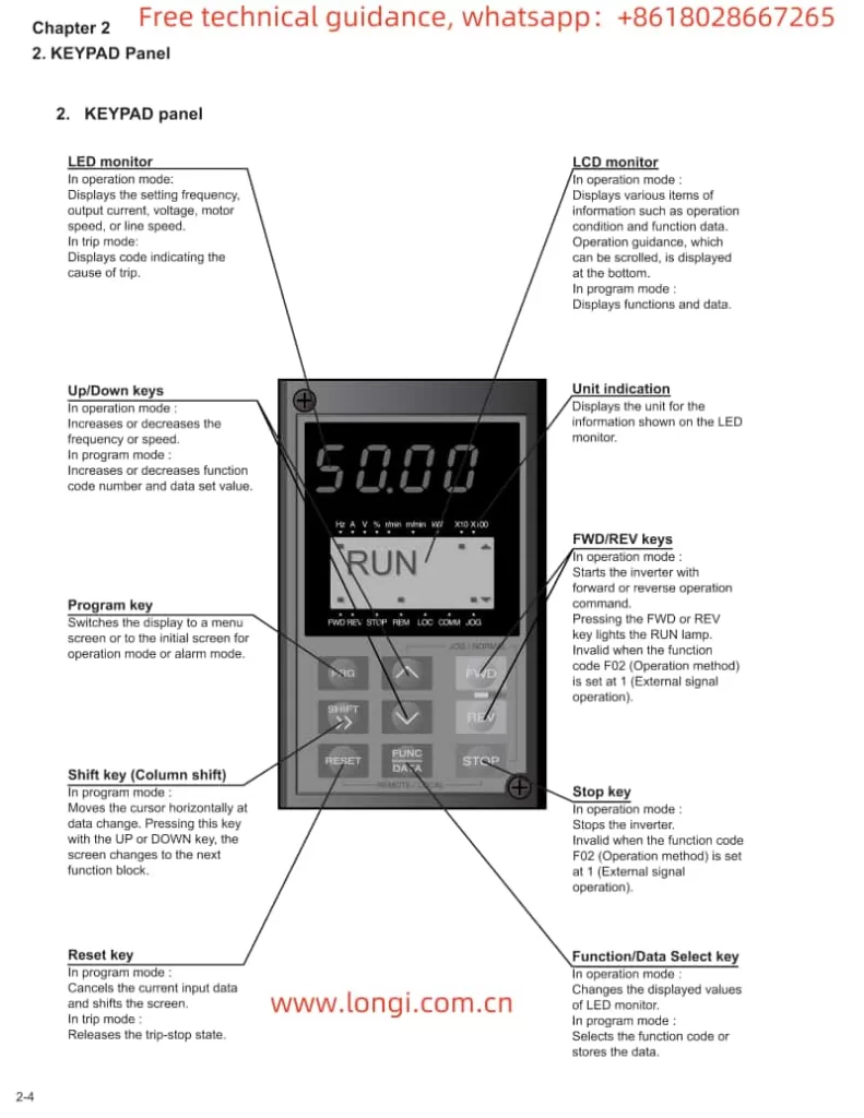
Fuji FRENIC5000G11SP11S KEYPAD PANEL

1.1 Button Functions

  • FWD/REV Keys: Used to start the frequency converter, enabling the motor to rotate forwards or backwards.
  • STOP Key: Used to stop the frequency converter.
  • ∨ or ∨ Keys: In program mode, these keys are used to vertically move the cursor to select function codes or data.
  • FUNC DATA Key: In program mode, this key is used to store modified data or switch display screens.
  • RESET Key: In program mode, this key is used to cancel the current input data; in fault mode, it is used to release the fault stop status.
  • PRG Key: Used to switch between operation mode and program mode.
  • SHIFT Key (Column Shift): In program mode, when used in combination with the ∨ or ∨ keys, it moves the cursor horizontally.

1.2 Restoring Factory Default Parameter Settings

To restore factory default parameter settings, follow these steps:

  1. Press the PRG key to enter program mode.
  2. Use the ∨ or ∨ keys to select “1. DATA SET”.
  3. Press the FUNC DATA key to confirm the selection.
  4. Simultaneously press the STOP key and the ∨ key to change the parameter protection value from “1” to “0”, allowing parameter modifications.
  5. Again, use the ∨ or ∨ keys to select “F00 Data protection” and set its value to “0”.
  6. Press the FUNC DATA key to save the settings. The frequency converter will restart and restore the factory default parameters.

1.3 Setting and Clearing Passwords

The Fuji FRENIC G11S/P11S series provides password protection to restrict access to parameters. However, the specific methods for setting and clearing passwords are not detailed in the provided manual. Typically, such functions may require setting through specific parameter codes, and the unlocking process may involve the manufacturer or authorized service personnel. It is recommended to refer to Fuji’s official technical support documentation or contact the manufacturer for detailed guidance.

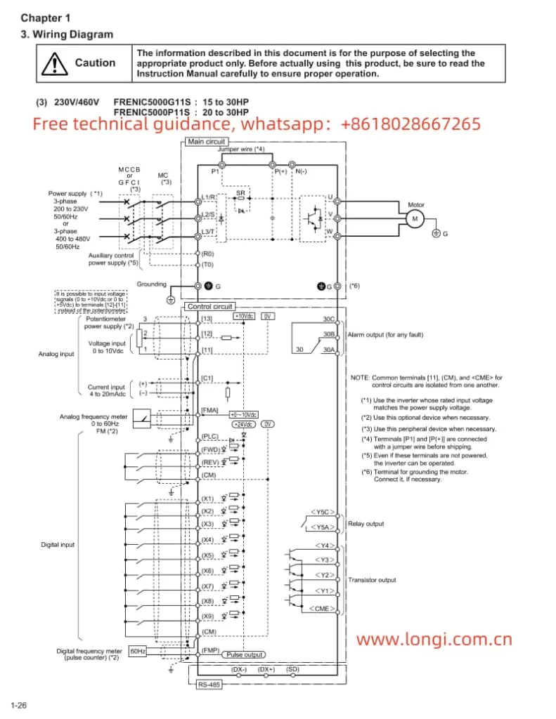
Fuji FRENIC5000 G11S/G9S Inverter wiring-diagraml

II. Terminal Start/Stop and Potentiometer Speed Regulation

2.1 Terminal Start/Stop

The Fuji FRENIC G11S/P11S series supports start/stop control via external terminals. To achieve this, relevant parameters need to be set correctly, and wiring must be done accordingly:

  • Parameter Setting: Set function code F02 to “1” to select external signal input mode.
  • Wiring: Connect the control power to terminals R0 and T0; connect the start signal (e.g., FWD) to the corresponding digital input terminal (e.g., X1); connect the stop signal to the REST terminal.

2.2 Potentiometer Speed Regulation

Potentiometer speed regulation is a method of changing the frequency output by adjusting the resistance value of an external potentiometer. The setup steps are as follows:

  • Parameter Setting: Set function code F01 to “1” to select voltage input mode.
  • Wiring: Connect the output terminal of the potentiometer to the frequency setting terminal of the frequency converter (e.g., terminal 12), and simultaneously ground the common terminal of the potentiometer (e.g., 0V terminal).

III. Frequency Converter Fault Code Analysis and Solutions

When the Fuji FRENIC G11S/P11S series encounters a fault, it will display the corresponding error code, helping users quickly locate the problem. The following are some common fault codes, their analyses, and solutions:

  • OC1: Overcurrent during acceleration. Possible causes include motor blockage, excessive load, or improper parameter settings. Solutions include checking the motor and load status, and adjusting acceleration time and current limit parameters.
  • OU: DC bus overvoltage. Possible causes include braking resistor failure, excessively short deceleration time, or abnormal supply voltage. Solutions include checking the braking resistor and wiring, and adjusting deceleration time and voltage limit parameters.
  • OL: Electronic thermal relay overload. Possible causes include motor overload, poor heat dissipation, or improper parameter settings. Solutions include checking the motor load and heat dissipation conditions, and adjusting the overload protection parameters.
  • Er1: Memory error. Possible causes include internal frequency converter faults or program abnormalities. Solutions include restarting the frequency converter; if the problem persists, contact the manufacturer for repair.

Summary

The Fuji Inverter FRENIC 5000 G11S/P11S series user manual provides detailed operation guides and parameter setting instructions, helping users fully utilize the various functions of the frequency converter. Through this guide, users can understand the functions of the operation panel, the method for restoring factory default parameter settings, the setup steps for terminal start/stop and potentiometer speed regulation, as well as the analysis and solutions for common fault codes. This information is crucial for ensuring the normal operation and efficient use of the frequency converter.