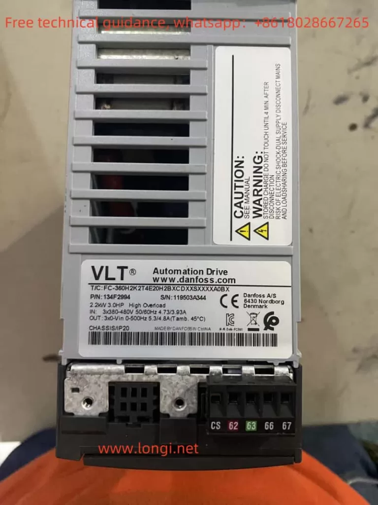
The Danfoss VLT® AutomationDrive FC 360 series is a powerful and versatile frequency converter suitable for a wide range of industrial control applications. This article will provide a detailed operation guide for this series of frequency converters, covering the control panel functions, parameter operations, terminal control, and fault code handling.
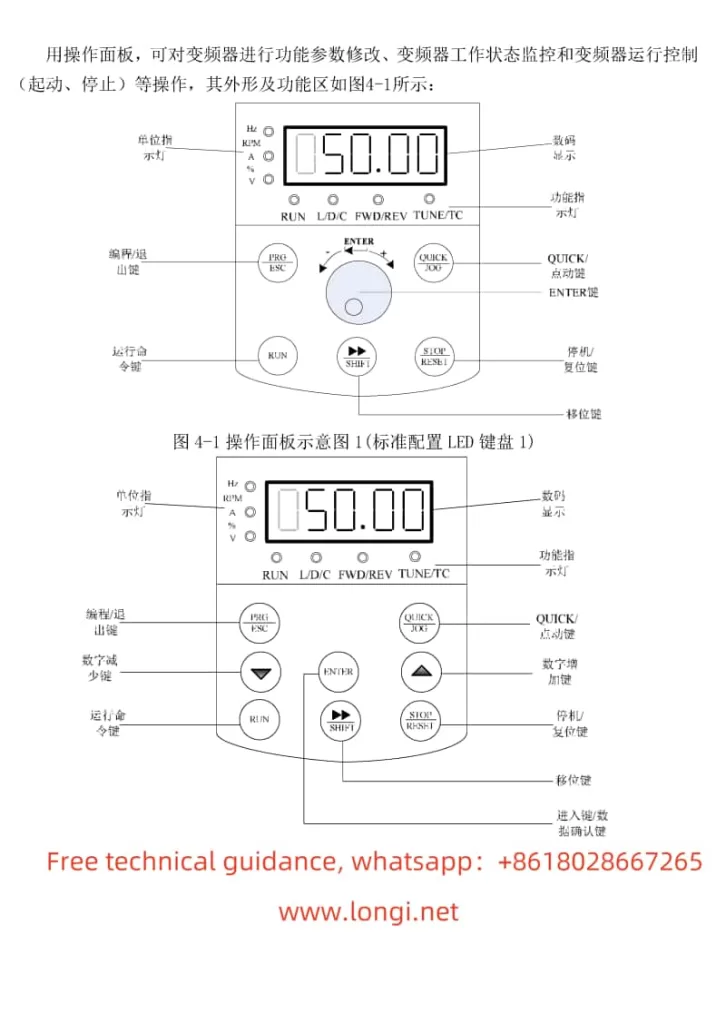
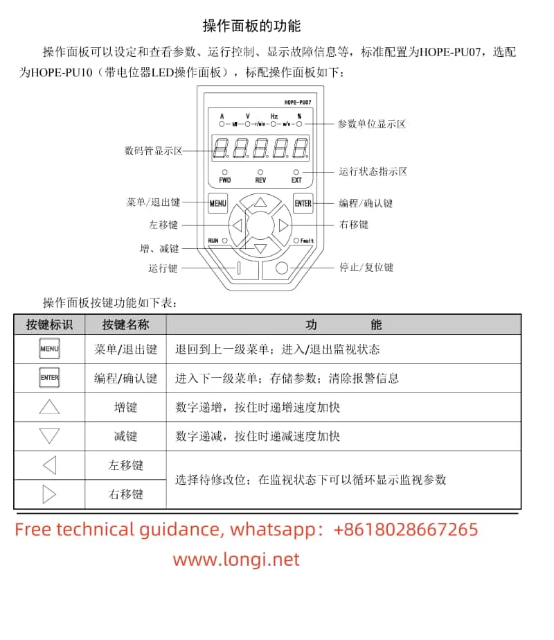
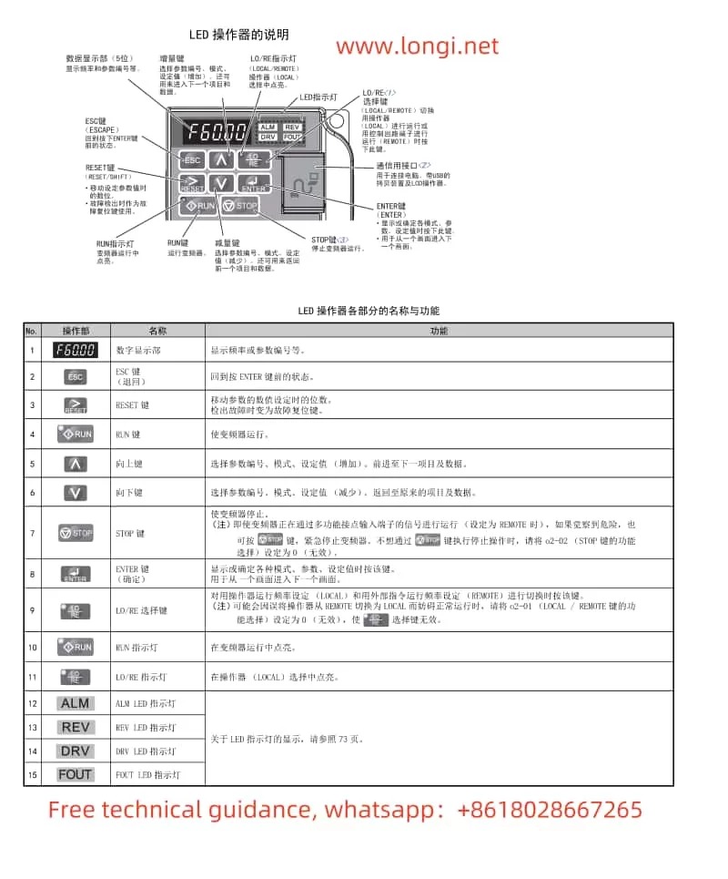
I. Control Panel Function Introduction
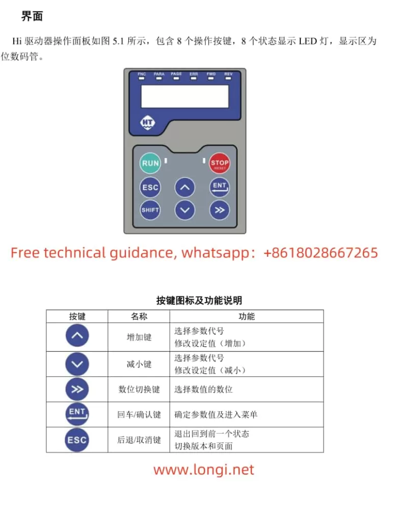
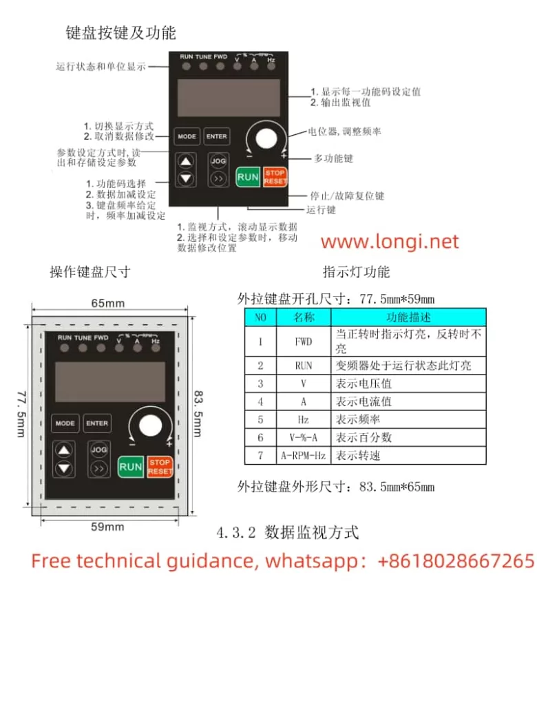
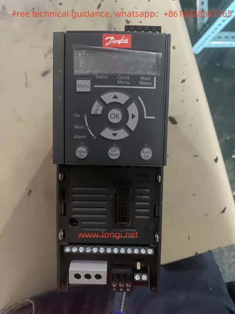
The Danfoss VLT® AutomationDrive FC 360 series offers two types of control panels: the Numeric Local Control Panel (NLCP) and the Graphical Local Control Panel (GLCP), to meet the needs of different users.
1.1 Basic Control Panel Operations
- Numeric Local Control Panel (NLCP):
- Display: Shows current operating parameters and status.
- Menu Key: Switches between status menu, quick menu, and main menu.
- Navigation Keys and Indicators: Used for parameter selection and value adjustment, with indicators showing the converter status.
- Operation Keys: Including [Hand On], [Auto On], [Reset], etc., for manual start, automatic start, and reset operations.
- Graphical Local Control Panel (GLCP):
- Similar functions to NLCP but with a larger display for richer information and multi-language support.
1.2 Parameter Copying and Restoration
- Parameter Copying:
- Upload parameters from Converter A to the control panel: On Converter A, enter the main menu, select “LCP Copy” function, and upload parameters to LCP.
- Download parameters from the control panel to Converter B: On Converter B, enter the main menu, select “LCP Copy” function, and download parameters from LCP to the converter.
- Parameter Initialization:
Enter the main menu, select the “Operating Mode” parameter, set it to “Initialize” and execute, or reset parameters to factory defaults. - Encryption and Parameter Level Settings:
Protect parameters from unauthorized changes by setting a password (parameter 0-60). Additionally, parameters 0-10 and 0-11 can be used to set the validity and editing permissions of different menus. - Compressor Control Parameter Settings:
Adjust startup parameters (e.g., 1-75 Startup Speed, 1-76 Startup Current), stop parameters (e.g., 1-80 Stop Function), and acceleration/deceleration times (e.g., 3-41 Ramp 1 Acceleration Time) according to compressor application requirements.
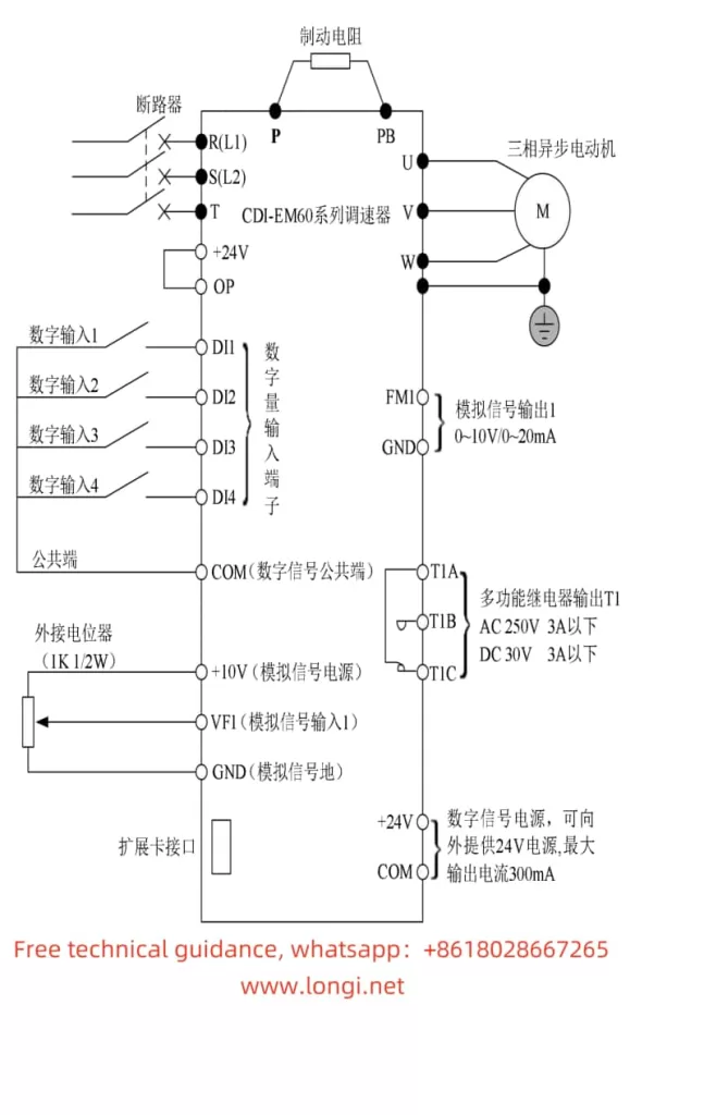
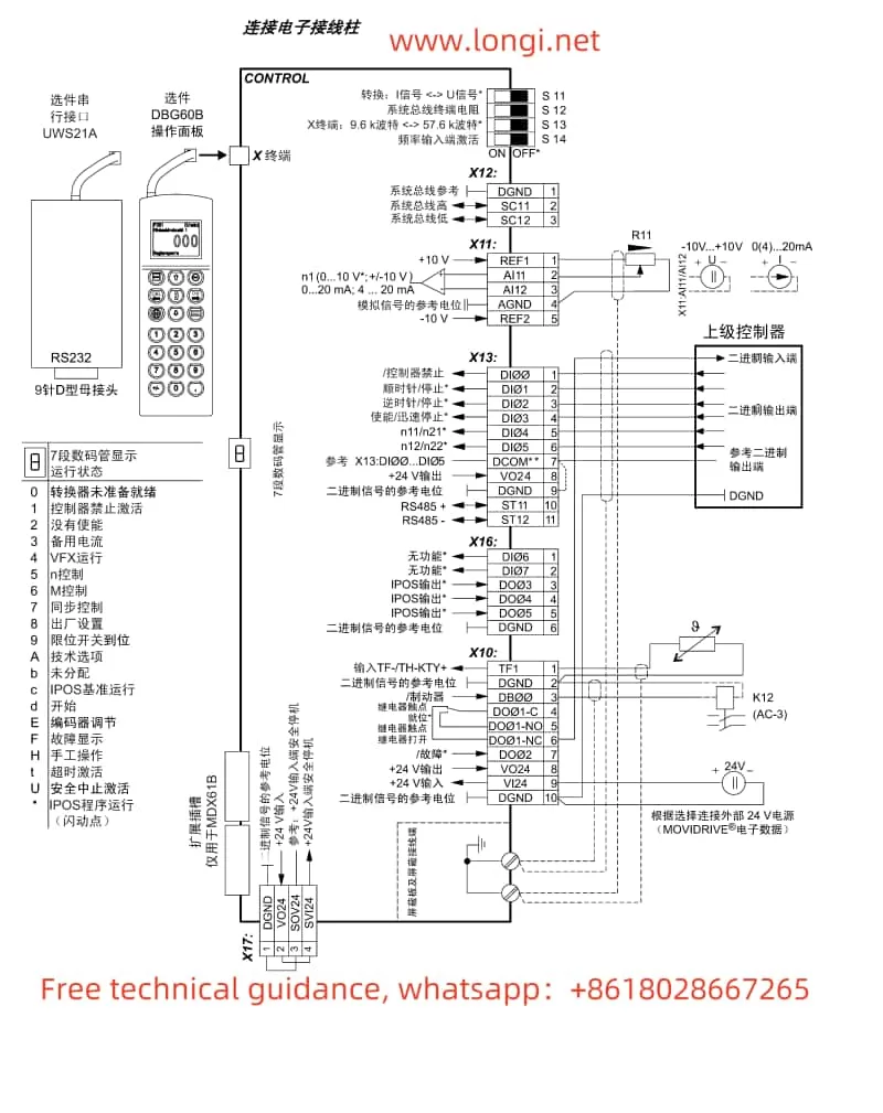
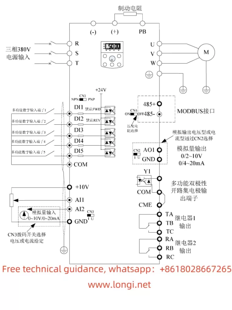
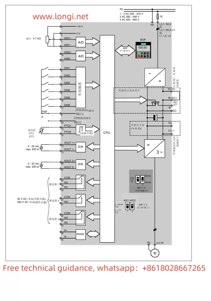
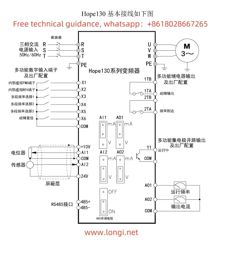
II. Terminal Forward/Reverse Control and External 4-20mA Frequency Setting
2.1 Forward/Reverse Control
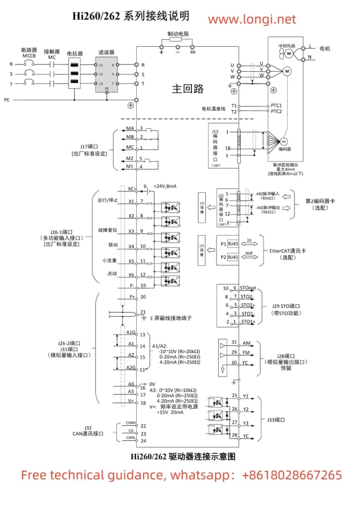
- Wiring:
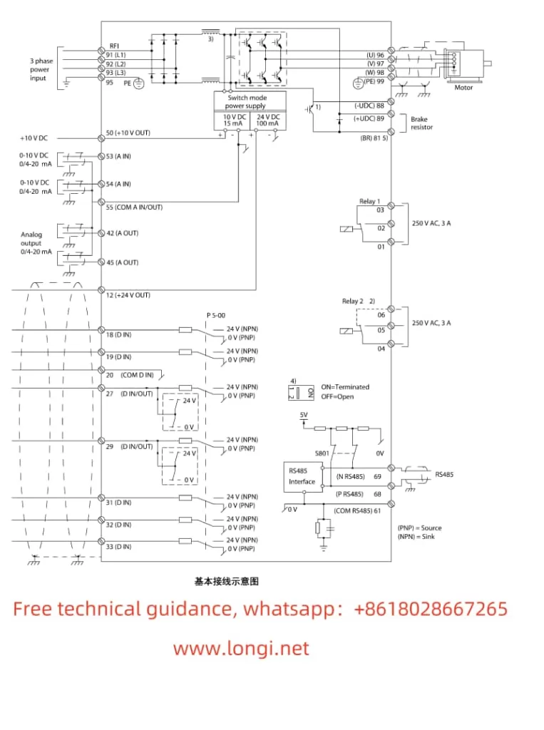
- Forward Control: Connect the control signal to terminal 18 (Digital Input [8] Start).
- Reverse Control: Connect the control signal to terminal 19 (Digital Input [10] Reverse).
- Parameter Settings:
- Enter the Digital Input parameter group (5-1*), and set the functions of terminals 18 and 19 to start and reverse, respectively.
2.2 External 4-20mA Frequency Setting
- Wiring:
- Connect the external 4-20mA signal to terminal 53 or 54 (depending on the analog input configuration).
- Parameter Settings:
- Enter the Analog Input parameter group (6-1* or 6-2*), and configure terminal 53 or 54 as a current input mode.
- Set the minimum and maximum values for the analog input (e.g., 6-10 Terminal 53 Low Voltage, 6-11 Terminal 53 High Voltage), as well as the corresponding feedback or reference value.
- In the Reference parameter group (3-1*), select the external analog input as one of the reference sources.
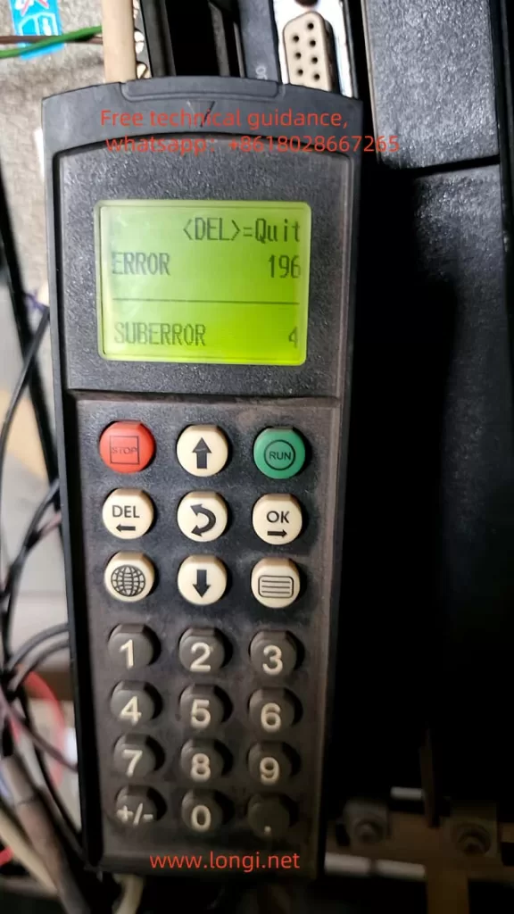
III. Fault Code Handling
The Danfoss VLT® AutomationDrive FC 360 series provides extensive fault codes to help users quickly locate and resolve issues.
- Common Fault Codes and Meanings:
- Alarm 14: Earth Fault: Output phase is discharging to earth through the cable between the motor and the converter or the motor itself.
- Alarm 16: Short Circuit: Short circuit occurs in the motor or motor circuit.
- Alarm 30: Motor Phase U Missing: Motor U phase is missing between the converter and the motor.
- Alarm 61: Feedback Error: Deviation exists between the calculated speed and the speed measurement value from the feedback device.
- Fault Handling:
- Refer to the fault diagnosis section in the user manual based on the fault code, check the corresponding circuit connections, motor status, and parameter settings.
- After resolving the fault, perform a reset operation through the control panel or an external reset signal to restore normal operation of the converter.
IV. Conclusion
The Danfoss VLT® AutomationDrive FC 360 series user manual provides a comprehensive operation guide, covering control panel functions, parameter operations, terminal control, and fault code handling. By mastering these operation guides, users can better use and maintain the frequency converter, ensuring its stable and reliable operation in various industrial control scenarios. In practical applications, users should also flexibly adjust parameter settings and control strategies based on specific application requirements and field environments to achieve optimal control effects.