I. Introduction to the Operation Panel Functionality and Key Parameter Settings
1.1 Introduction to the Operation Panel Functionality
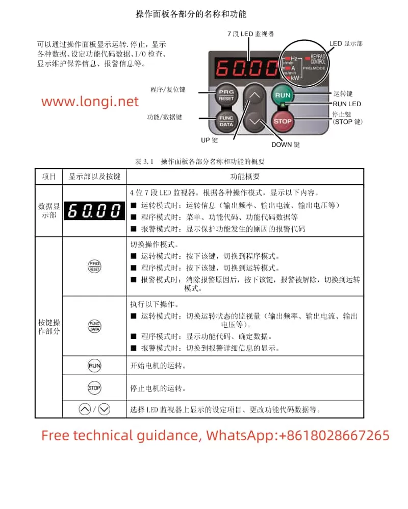
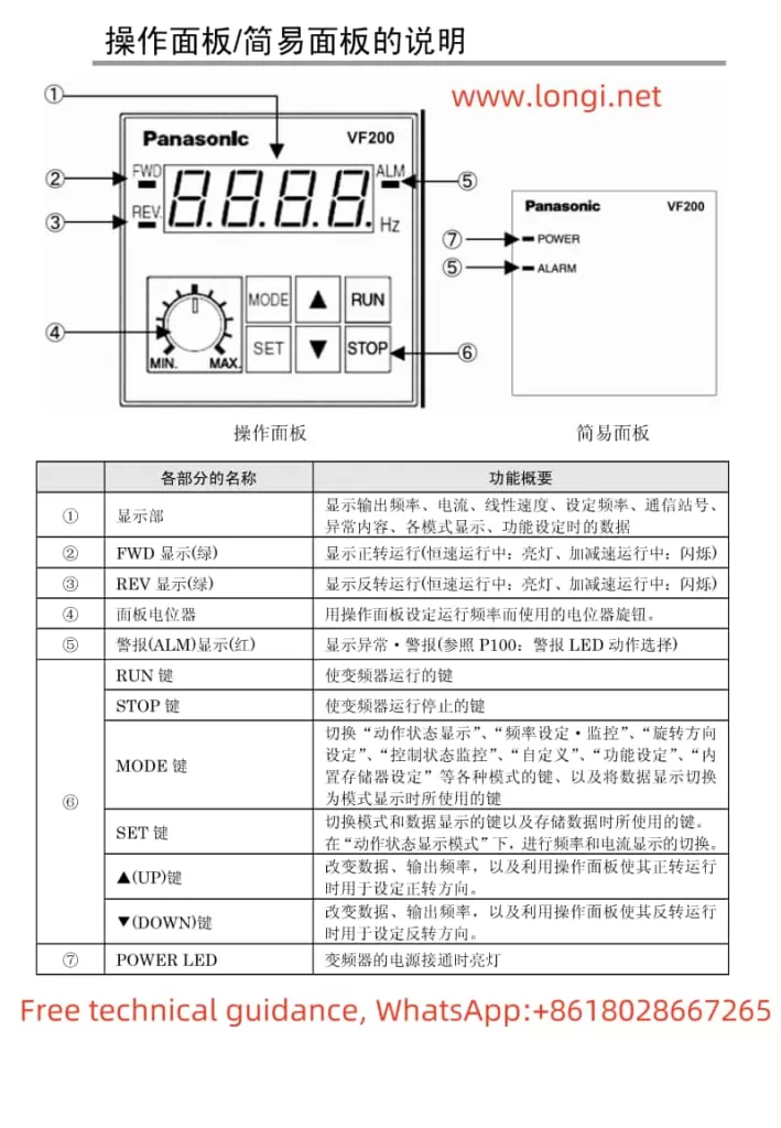
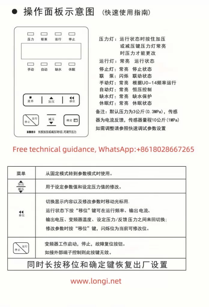
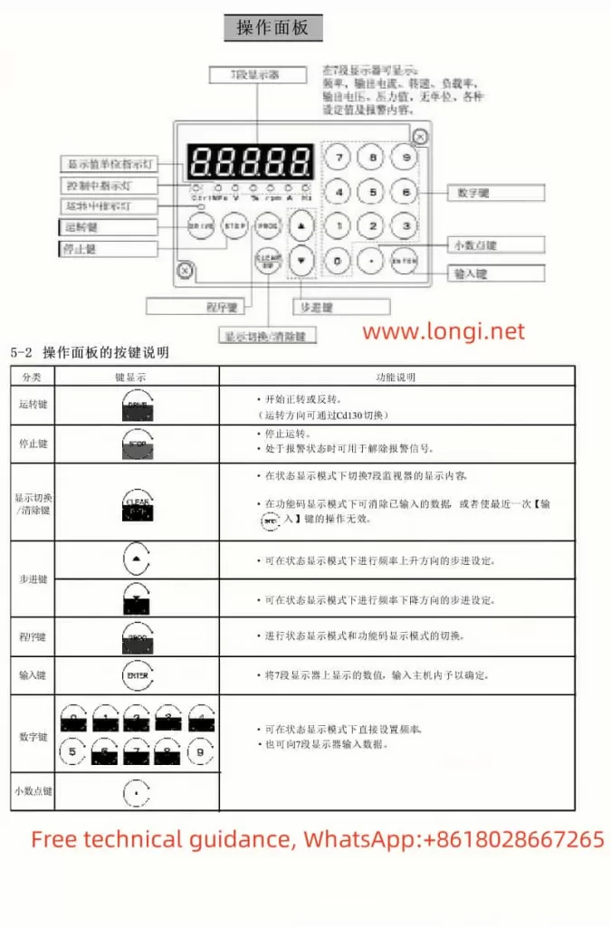
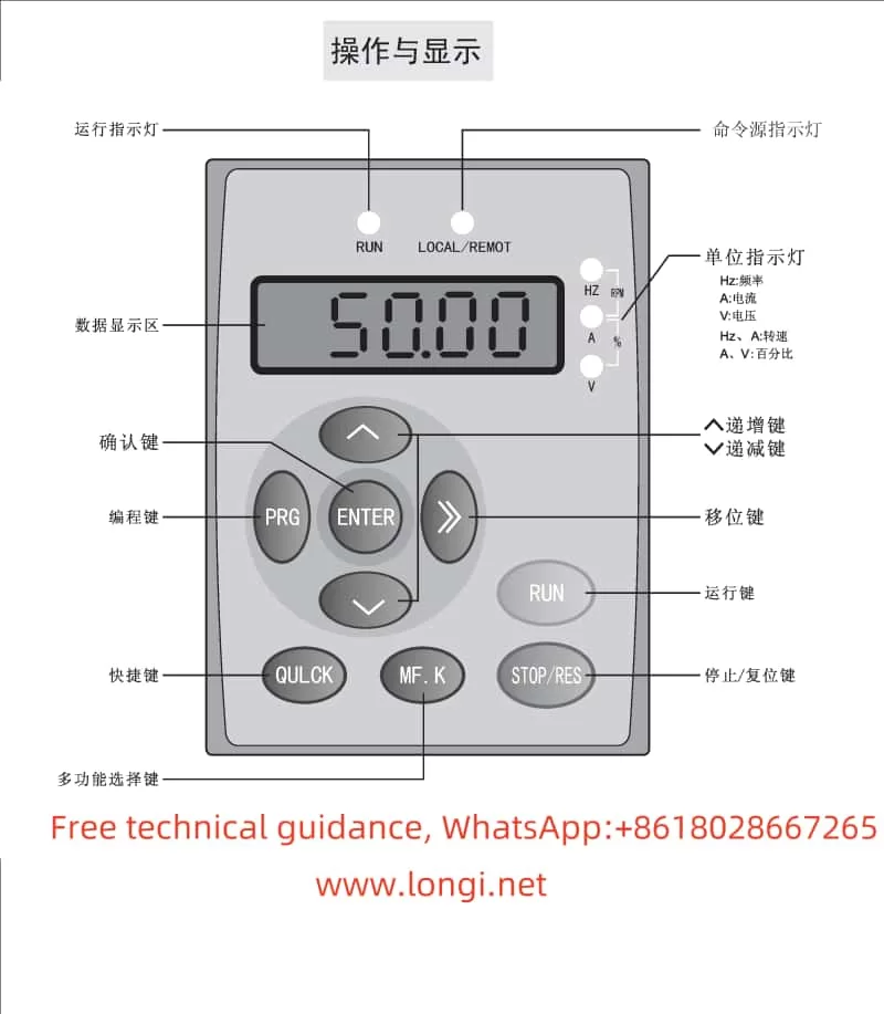
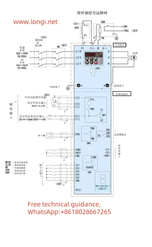
The Fuji Frequency Converter FRENIC-Multi (FRN E1S) series features an intuitive operation panel that allows users to easily monitor and control the operation of the frequency converter. The operation panel provides various functions such as setting operating frequencies, monitoring operating status, and configuring parameters.
Key Features of the Operation Panel:
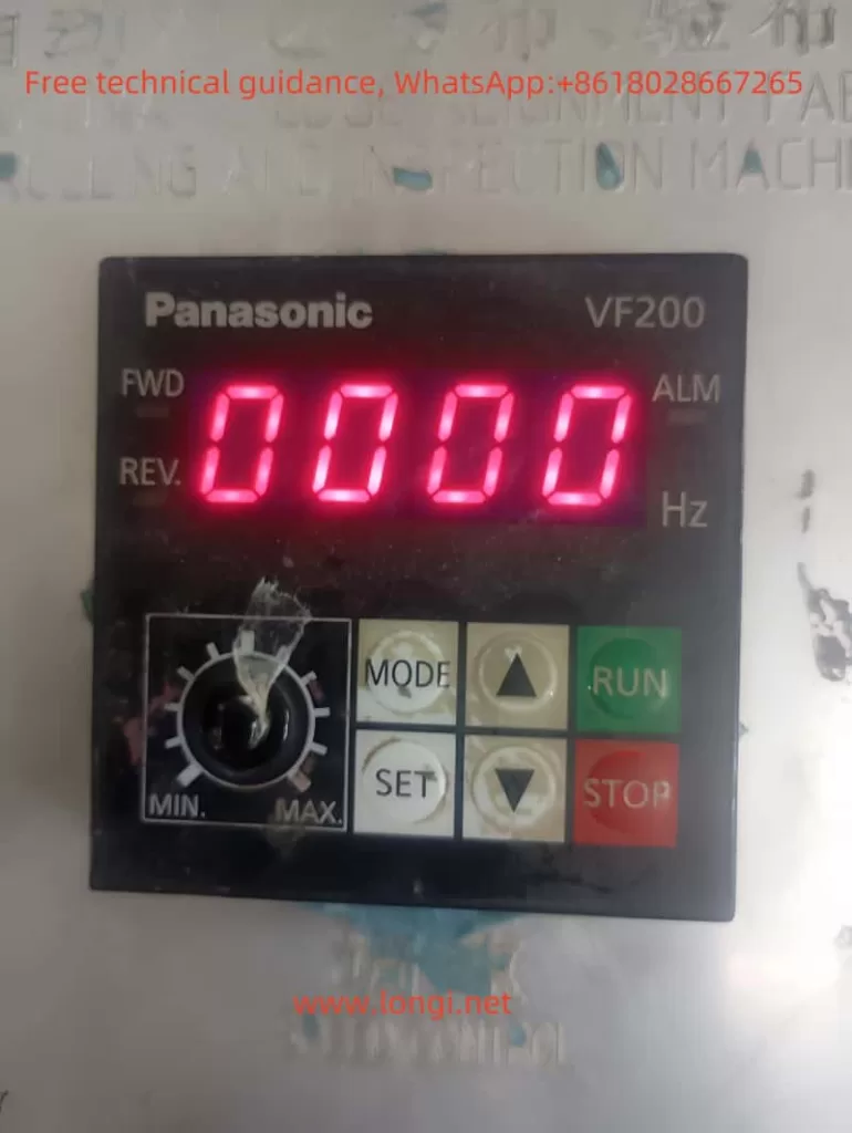
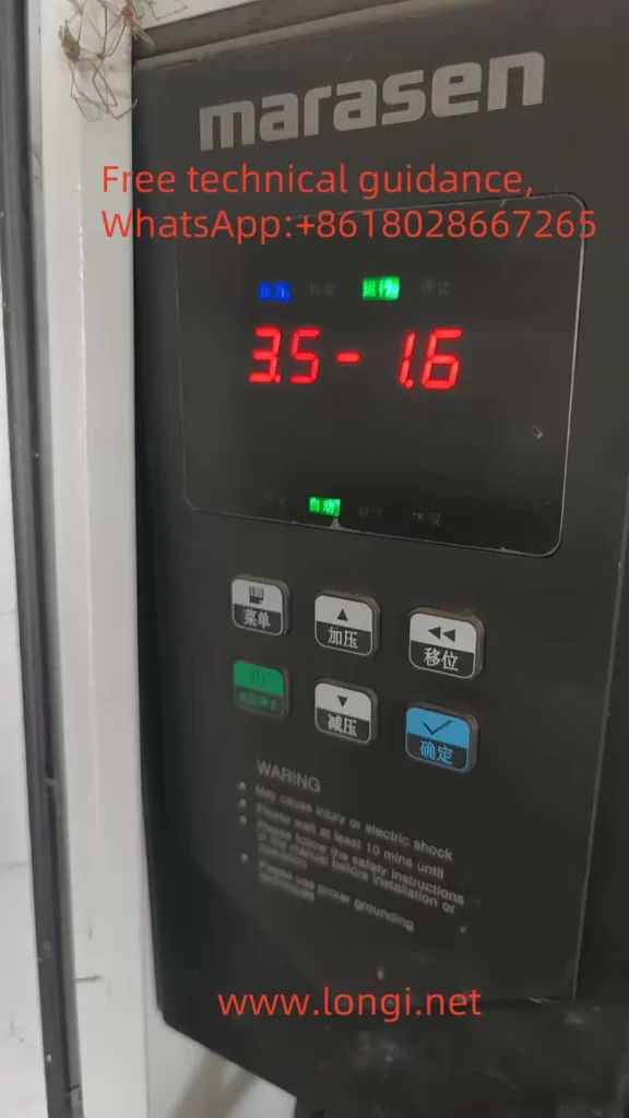
- LED Display: Displays various operating parameters such as output frequency, output current, and operating status.
- UP/DOWN Keys: Used to adjust the set frequency.
- RUN/STOP Keys: Used to start and stop the motor.
- Mode Selection Keys: Allows switching between operation modes such as run mode, program mode, and alarm mode.
1.2 Setting the Electronic Thermal Relay Function
The electronic thermal relay function protects the motor from overheating by monitoring the output current of the frequency converter. To configure this function, the following parameters need to be set:
- F10 (Thermal Relay Characteristic Selection): Selects the cooling system characteristic of the motor. Options include self-cooled motors with built-in fans and externally cooled motors.
- F11 (Thermal Relay Action Value): Sets the current level at which the thermal relay will trip. This value should typically be set to around 100-110% of the motor’s rated current.
- F12 (Thermal Time Constant): Sets the time it takes for the thermal relay to trip after the current exceeds the action value. This value depends on the motor’s thermal properties and the ambient operating conditions.
1.3 Configuring the Instantaneous Power Failure Restart Function
The instantaneous power failure restart function allows the frequency converter to automatically restart the motor after a temporary power outage. To enable and configure this function, the following parameters need to be set:
- F14 (Instantaneous Power Failure Restart Selection): Enables or disables the instantaneous power failure restart function. Options include no restart (instant trip), no restart with reset on power restoration, restart at the frequency at the time of power failure (for general loads), and restart at the start frequency (for low-inertia loads).
- H13 (Restart Waiting Time): Sets the time to wait after detecting a power failure before attempting to restart the motor. This helps to ensure that the residual voltage in the motor windings has decayed sufficiently to prevent inrush currents.
- H14 (Frequency Ramp-Down Rate): Sets the rate at which the output frequency is reduced during restart to synchronize with the motor’s rotational speed and prevent excessive currents.
- H16 (Instantaneous Power Failure Allowable Time): Sets the maximum time that can elapse after a power failure before the restart function is disabled.
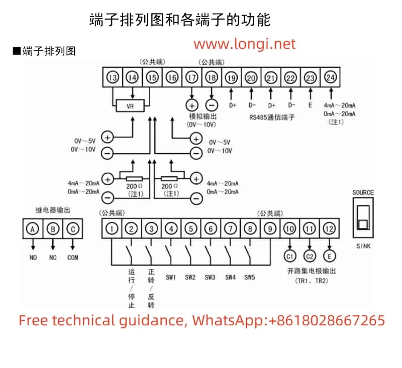
1.4 Selecting and Configuring the Terminal FM Function
The terminal FM provides an analog output signal that can be used to monitor various operating parameters of the frequency converter. To select and configure this function, the following steps are required:
- F29 (Terminal FM Action Selection): Selects whether the terminal FM outputs a voltage signal (0-10V) or a pulse signal.
- F30 (Output Gain): Adjusts the gain of the analog output signal. This allows scaling the output signal to match the input range of the monitoring equipment.
- F31 (Function Selection): Selects the parameter to be monitored and output through the terminal FM. Options include output frequency, output current, output voltage, motor torque, load rate, and more.
- F33 (Pulse Rate): When pulse output is selected, this parameter sets the pulse rate at 100% output.
By carefully configuring these parameters, users can fully utilize the advanced functionality of the Fuji FRENIC-Multi (FRN E1S) series frequency converter to optimize motor control and protect against potential faults.