I. Introduction to the Function of Huayuan Inverter G1 Series Operating Panel (Keyboard)
Operating Panel Functionality
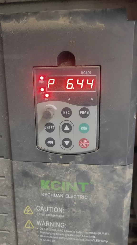
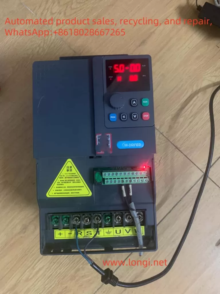
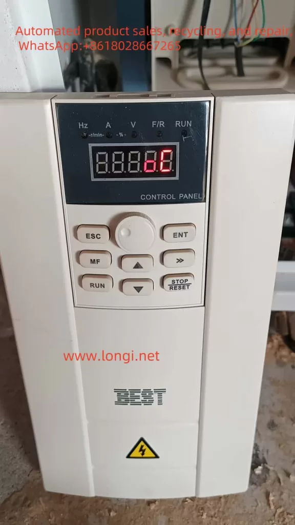
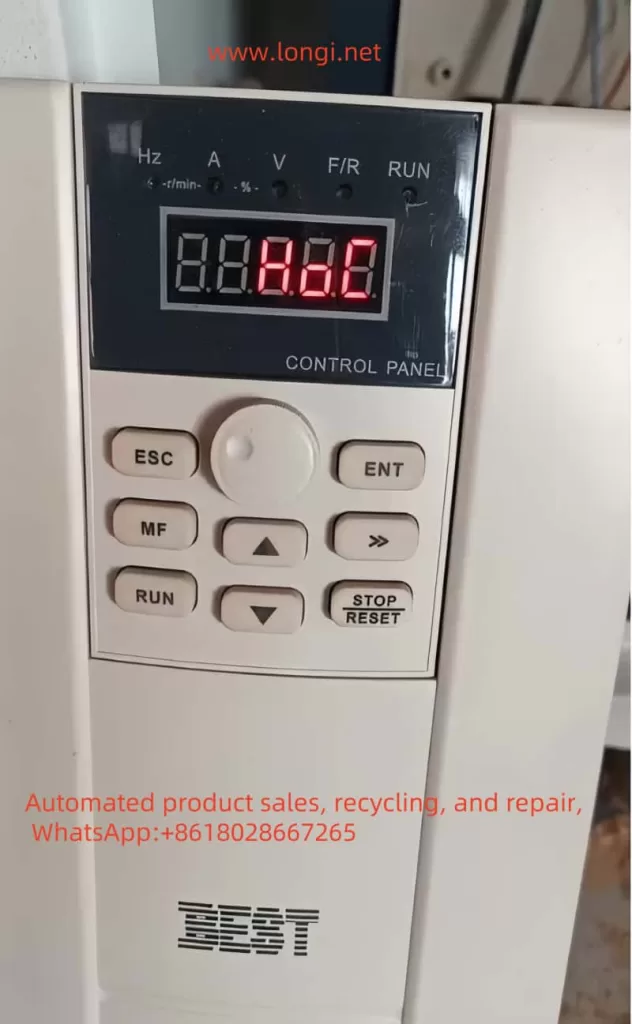
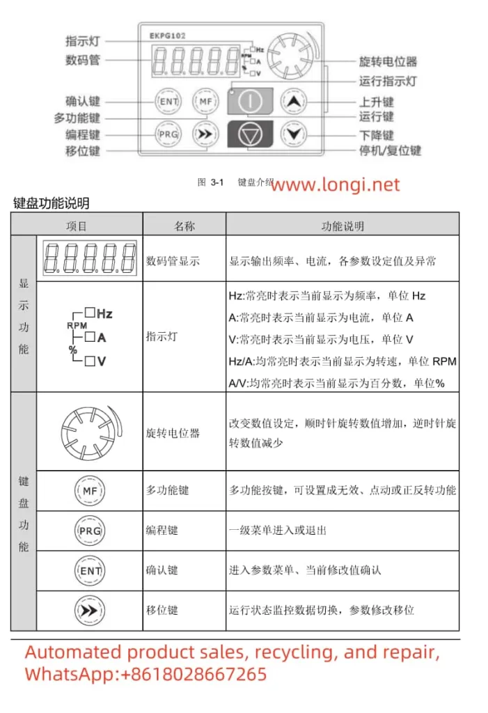
The Huayuan Inverter G1 Series operating panel integrates multiple functions to facilitate parameter setting, status monitoring, and fault diagnosis. The panel primarily consists of a 5-digit 8-segment LED display, 4 indicator lights, 8 buttons, and a rotary potentiometer.
- LED Display: Shows output frequency, current, various parameter settings, and abnormal statuses.
- Indicator Lights: Indicate the current operating mode (e.g., Hz, A, V).
- Button Functions:
- Rotary Potentiometer: Used to adjust numerical settings; clockwise rotation increases the value, while counterclockwise rotation decreases it.
- Multifunction Button: Can be set to invalid, jog, or forward/reverse functions.
- Program Button: Enters or exits the parameter menu.
- Confirm Button: Enters the parameter menu and confirms current modifications.
- Shift Button: Switches between running status monitoring data and shifts parameters during modification.
- Run Button: Controls the start and stop of the inverter.
- Stop/Reset Button: Stops the inverter or resets faults.
- Up/Down Buttons: Increases or decreases function codes or values.
Parameter Upload and Download
- Parameter Upload: Copies the internal parameters of the inverter to the keyboard memory. Set function parameter P07.02=H.#1, press the “‖” button to start the upload, and “CoPy” will be displayed upon completion.
- Parameter Download: Writes the parameters stored in the keyboard to the inverter. Set function parameter P07.02 to H.12 or H.13, press the “‖” button to start the download, and “LoAd” will be displayed upon completion.
Setting Open-Loop Vector Control (SVC) and Closed-Loop Vector Control (FVC) Modes
- Open-Loop Vector Control (SVC):
- Set P00.00=1.
- Set motor parameters (P02.01~P02.05) according to the motor nameplate.
- Perform motor parameter tuning (P00.25=1 for static tuning, P00.25=2 for dynamic tuning).
- Closed-Loop Vector Control (FVC):
- Set P00.00=2.
- Set motor parameters (P02.01~P02.05) according to the motor nameplate.
- Set encoder-related parameters (e.g., P20.00 sets the encoder line count, P20.02 enables the PG card encoder function).
- Perform motor parameter tuning (P00.25=1 for static tuning, P00.25=2 for dynamic tuning).
Initializing Parameters
- By setting function parameter P00.26, you can choose to restore factory default parameters (excluding or including motor parameters).
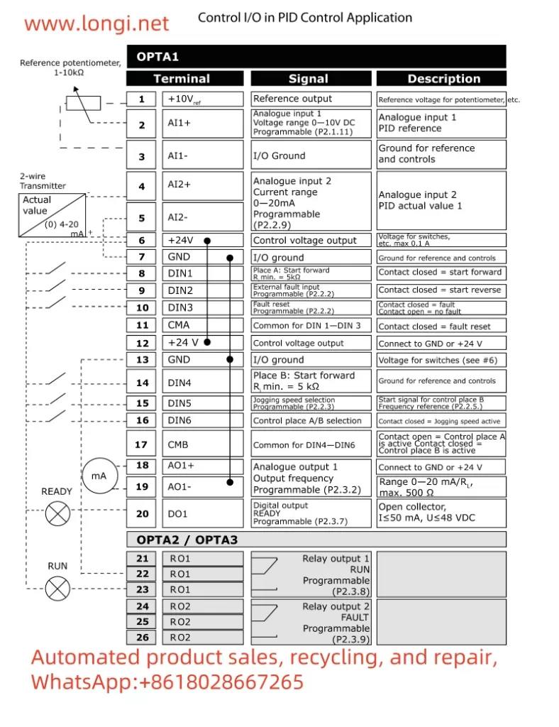
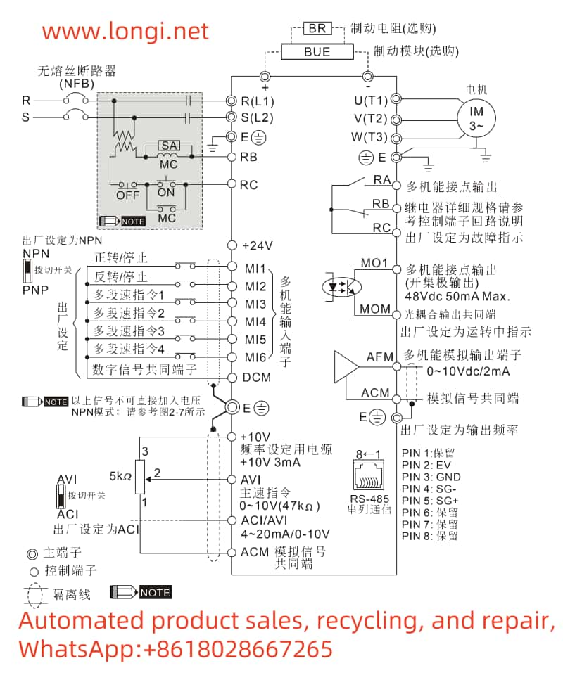
II. External Terminal Control
Achieving Forward/Reverse Rotation and Potentiometer Speed Adjustment
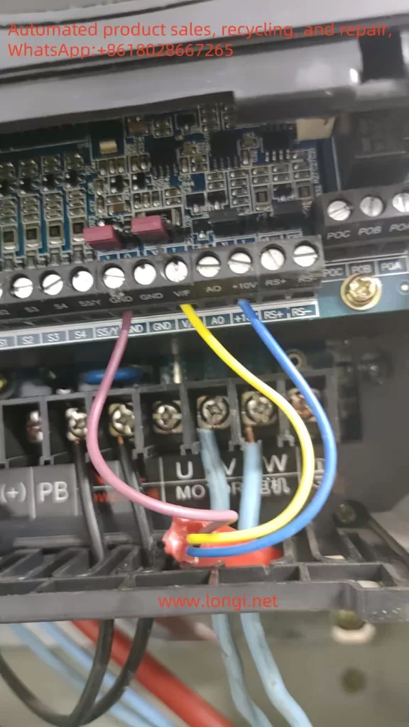
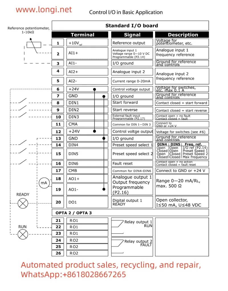
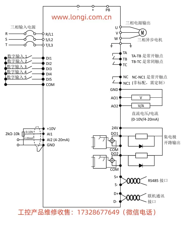
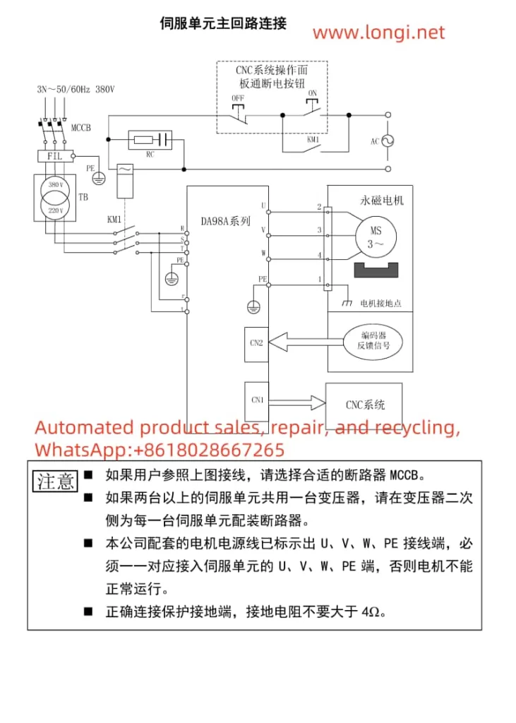
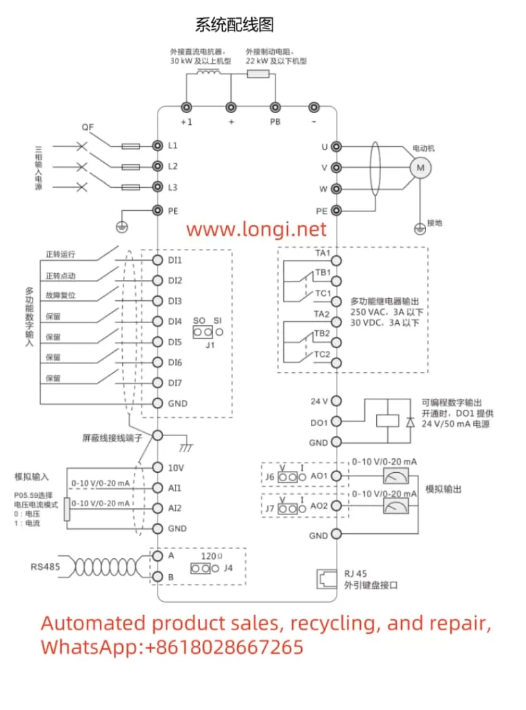
Terminal Connections
- Forward/Reverse Control:
- For forward rotation, connect the DI1 terminal to the common terminal (COM).
- For reverse rotation, connect the DI2 terminal to the common terminal (COM).
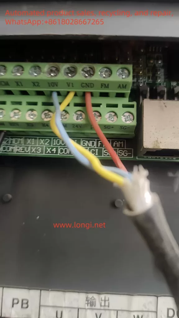
- Potentiometer Speed Adjustment:
- Connect the output end of the external potentiometer to AI1 or AI2, and the other end to the common terminal (COM).
Parameter Settings
- Forward/Reverse Parameters:
- Set P05.00 (DI1 function) = 1 (forward rotation) or 2 (reverse rotation).
- Ensure P00.01 (command source selection) = 0 (keyboard control) or change it to 1 (terminal control) as needed.
- Potentiometer Speed Adjustment Parameters:
- Set P00.02 (main frequency source X selection) = 1 (AI1) or select other analog inputs as needed.
- Ensure P05.59 (AI voltage or current selection) is set correctly (e.g., 00 indicates AI1 is a voltage input).
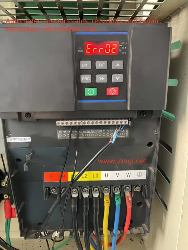
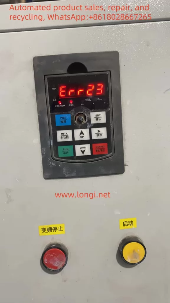
III. ERR02 Fault Solution
Meaning of ERR02 Fault
ERR02 indicates an “acceleration overcurrent fault,” meaning an overcurrent is detected during inverter acceleration.
Fault Causes and Solutions
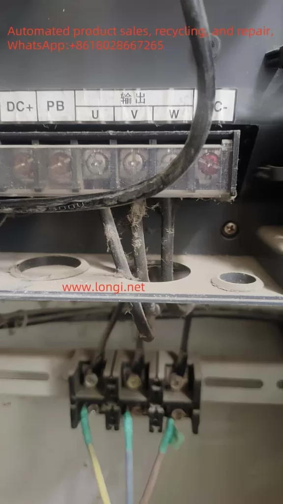
- Grounding or Short Circuit in Inverter Output Circuit:
- Check and eliminate grounding or short circuits in peripheral wiring.
- Vector Control Mode Without Parameter Tuning:
- Ensure motor parameter tuning has been correctly performed (SVC or FVC mode).
- Too Short Acceleration Time:
- Increase the acceleration time (P00.17 or P00.18).
- Inappropriate Manual Torque Boost or V/F Curve:
- Adjust the manual torque boost (P04.01) or select an appropriate V/F curve (P04.00).
- Low Voltage:
- Adjust the voltage to the normal range.
- Starting a Rotating Motor:
- Choose speed tracking start or wait for the motor to stop before starting.
- Sudden Load Increase During Acceleration:
- Eliminate sudden load increases or reassess the load condition.
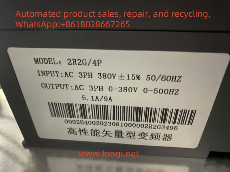
- Undersized Inverter Selection:
- Select an inverter with a higher power rating.
Repairing the Inverter
If the above methods cannot resolve the ERR02 fault, further inspection and repair of the inverter may be necessary:
- Check the Drive Board and Main Control Board:
- Confirm that the drive board and main control board are functioning normally, and replace faulty components if necessary.
- Check the Hall Sensor:
- Confirm that the Hall sensor is operating correctly, and replace it if damaged.
- Contact the Manufacturer or Professional Repair Service:
- If the problem persists, it is recommended to contact the inverter manufacturer or a professional repair service for further inspection and repair.
Conclusion
The Huayuan Inverter G1 Series user manual provides a detailed operation guide and fault solution. By correctly setting parameters and using external terminal control, various functions of the inverter can be realized. For the ERR02 fault, the inverter can be restored to normal operation by troubleshooting and solving the problem step by step. When necessary, contacting the manufacturer or a professional repair service is crucial to ensuring reliable operation of the equipment.