I. Introduction to XRF Technology and Innov-X Alpha Series Performance Characteristics
1.1 Introduction to XRF Technology
X-Ray Fluorescence Spectrometry (XRF) is a powerful tool for elemental analysis and quantification. It works on the principle that different elements, when excited by X-rays, emit fluorescent X-rays with specific energies or wavelengths. These characteristics of the emitted X-rays can be used to identify and quantify the elements present in a sample.
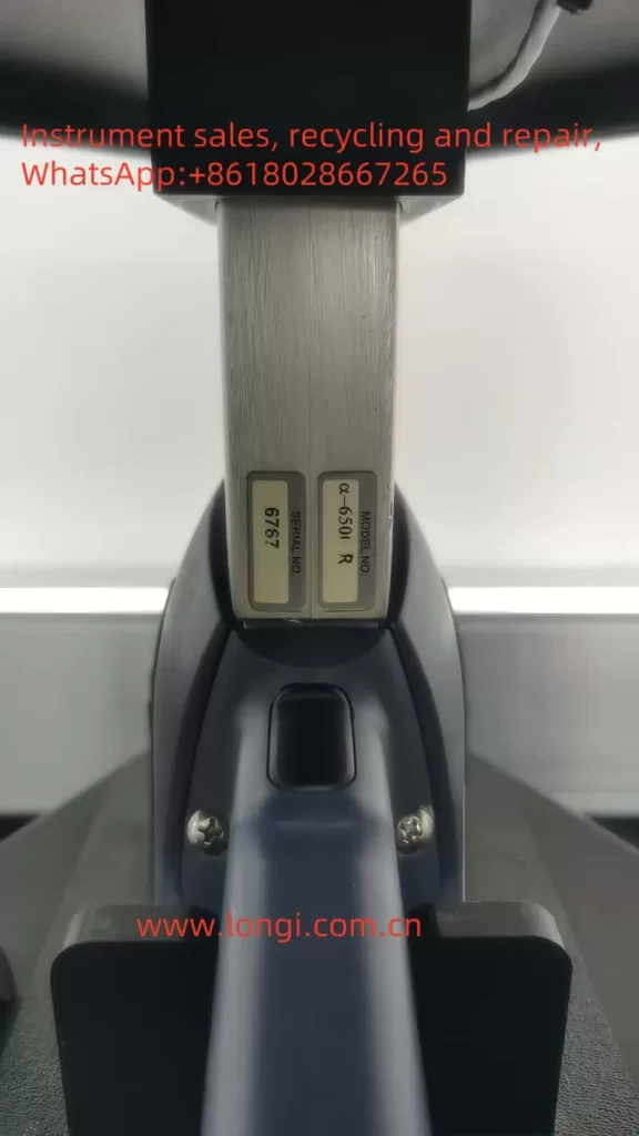
1.2 Innov-X Alpha Series Performance Characteristics
The Innov-X Alpha series of spectrometers are portable XRF analyzers featuring the following notable characteristics:
- Portability: Designed for handheld use, facilitating on-site analysis.
- Battery-Powered: Equipped with rechargeable lithium-ion batteries for extended operation.
- High Precision: Utilizes a high-resolution silicon PIN diode detector for accurate elemental analysis.
- Versatility: Suitable for analyzing alloys, soils, paints, and various other sample types.
- User-Friendly: Integrated with an HP iPAQ Pocket PC for an intuitive operation interface.
- Automatic Compensation: Automatically compensates for irregular or small samples, enhancing analysis accuracy.
II. Basic Operational Workflow and Radiation Safety Precautions
2.1 Basic Operational Workflow
- Inspection and Preparation: Ensure all accessories are present, batteries are fully charged, and the iPAQ is also charged.
- Power-On: Press the power switch on the back of the analyzer, followed by the power button on the iPAQ.
- Software Initiation: Select the Innov-X software on the iPAQ to begin using the analyzer.
2.2 Radiation Safety Precautions
- Pre-Operational Preparation: Ensure operators have undergone radiation safety training and obtained the corresponding certificate.
- Operational Norms: Never point the analyzer at any part of the body, especially during testing.
- Radiation Warnings: Pay attention to the red indicator light on the analyzer and the warning label on the back, ensuring no one is around during testing.
- Regular Monitoring: Use personal dosimeters to regularly monitor radiation exposure.
III. Routine Operational Procedures
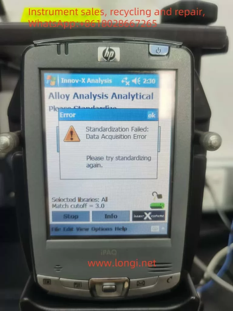
3.1 Standardization Procedure
- Steps: Perform standardization before each use or after hardware reset. Place the standardization cap over the analyzer probe and press the standardization button on the screen, waiting for completion.
- Precautions: If standardization fails, check the placement of the cap, battery level, and restart the analyzer if necessary.
3.2 Software Trigger Lock
- Function: Prevents accidental triggering, ensuring safe operation.
- Operation: Unlock the trigger by tapping the lock icon on the iPAQ screen before testing. The trigger will automatically lock if no test is performed within five minutes.
3.3 Testing and Outputting Results
- Testing: Align the probe with the sample and press the trigger or the start button on the iPAQ to initiate testing.
- Viewing Results: Upon completion, results will automatically display on the iPAQ screen. Detailed data and spectra can be viewed on the results screen.
- Data Export: Use ActiveSync software to connect the iPAQ to a computer and export test results to Excel or other software for further analysis.
IV. Operating Guide for Soil Mode
4.1 Soil Mode Setup
- Mode Selection: Choose the “Soil” mode from the main menu.
- Test Time Settings: Configure the minimum and maximum test times, as well as the test end conditions (e.g., maximum time, relative standard deviation).
4.2 Testing Steps
- Sample Preparation: Place the soil sample in a test cup or on the test stand, ensuring it fully covers the probe window.
- Initiate Testing: Press the trigger or the start button on the iPAQ to begin testing.
- Result Analysis: After testing, review the element concentrations and spectra on the results screen, and export data as needed.
V. Fault Analysis and Troubleshooting
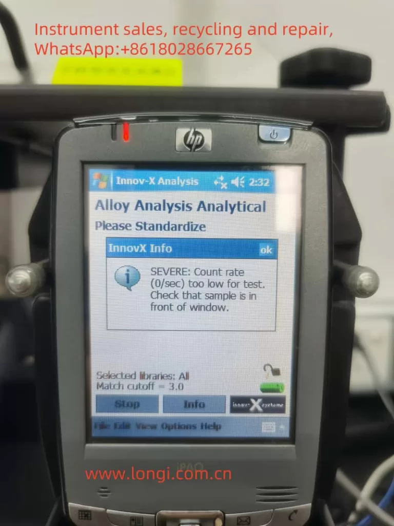
5.1 Inability to Standardize (Low Count Rate)
- Possible Causes: Insufficient battery power, improper placement of the standardization cap, detector contamination or damage.
- Troubleshooting:
- Check the battery level and ensure it is fully charged.
- Reposition the standardization cap to ensure it fully covers the probe window.
- Clean the detector window to remove any dirt or obstructions.
- If the issue persists, contact Innov-X technical support for further inspection and repair.
VI. Conclusion
The Innov-X Alpha series of spectrometers, with their portability, high precision, and versatility, offer wide applications in the field of elemental analysis. By following the operational procedures and radiation safety precautions outlined in this user guide, operators can safely and effectively conduct analyses on various samples. Additionally, understanding common faults and troubleshooting methods will help ensure the stable operation of the analyzer and extend its service life.