1. Panel Startup, Speed Adjustment, Password Setting & Removal, and Parameter Initialization
Panel Startup and Speed Adjustment
The KCLY INVERTER KOC600 series supports startup and speed adjustment via the operation panel. To set up panel startup:
- Ensure the command source is set to the operation panel: Navigate to the parameter
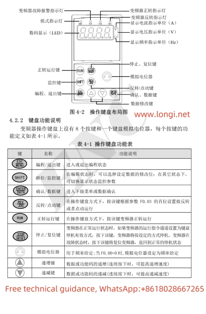
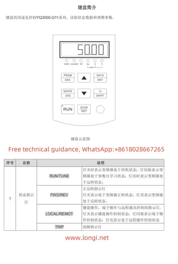
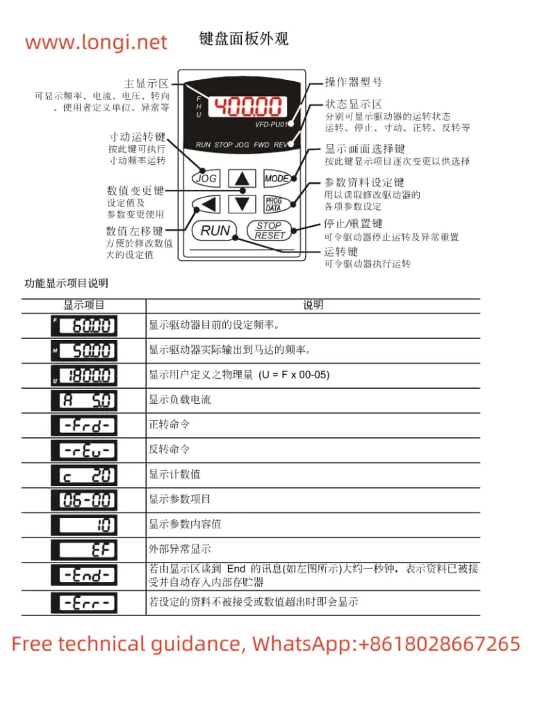
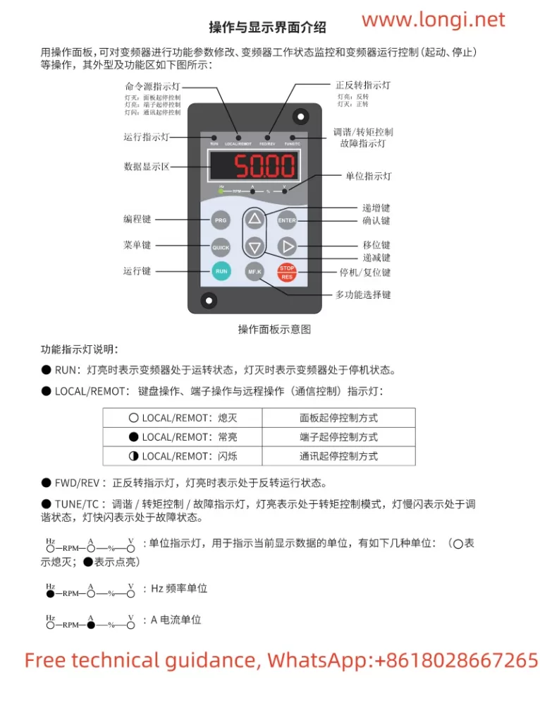
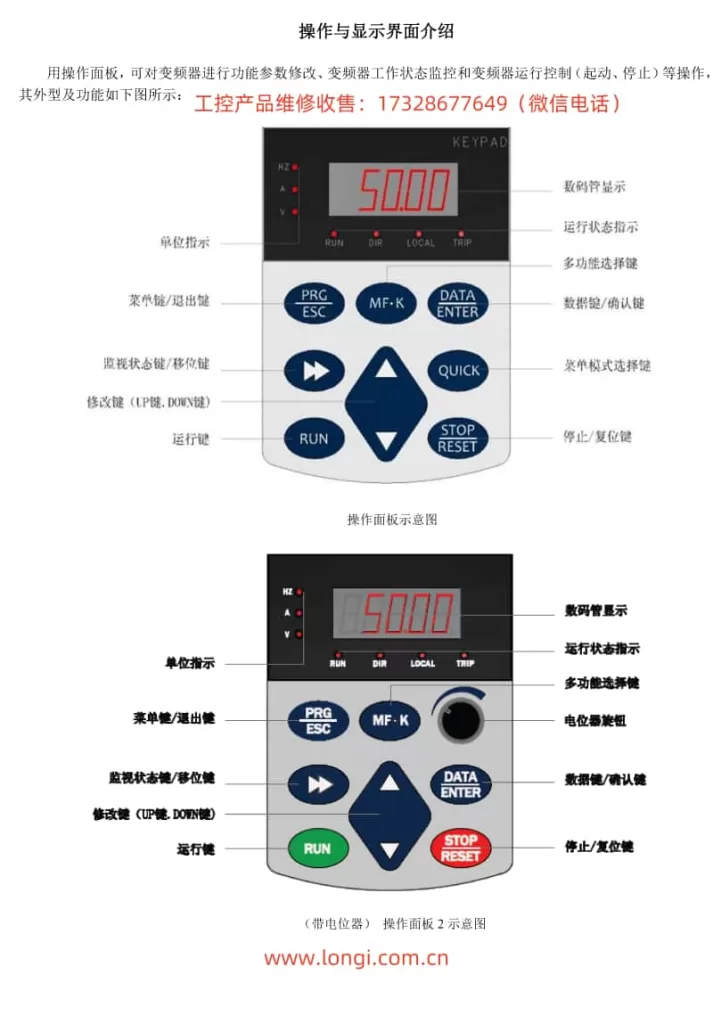
b0-02and set it to0(Operation Panel Command Channel). This ensures that the startup and speed commands come from the panel. - Adjust the frequency: Use the
▲and▼keys on the panel to increase or decrease the set frequency (b0-12). The motor will run at the set frequency once the startup command is given.
Password Setting and Removal
To set a password for the KOC600 series inverter:
- Navigate to the password parameter: Go to parameter
A0-00and enter the desired password value (0-65535). - Save and exit: Press the
DATA/ENTERkey to save the password setting.
To remove the password:
- Enter the current password: Go to parameter
A0-00and enter the current password. - Clear the password: Set the value to
0and press theDATA/ENTERkey to save.
Parameter Initialization
To initialize the parameters to their factory defaults:
- Navigate to the initialization parameter: Go to parameter
A0-09. - Select the initialization option: Set
A0-09to1to restore factory settings excluding motor parameters,2to restore factory settings including motor parameters, or3for reserved purposes. - Save and reset: Press the
DATA/ENTERkey to save and reset the parameters.
2. External Terminal Startup and Pulse Frequency Speed Adjustment
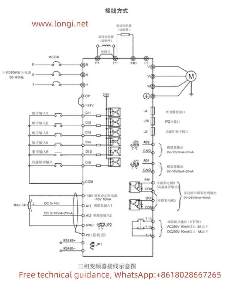
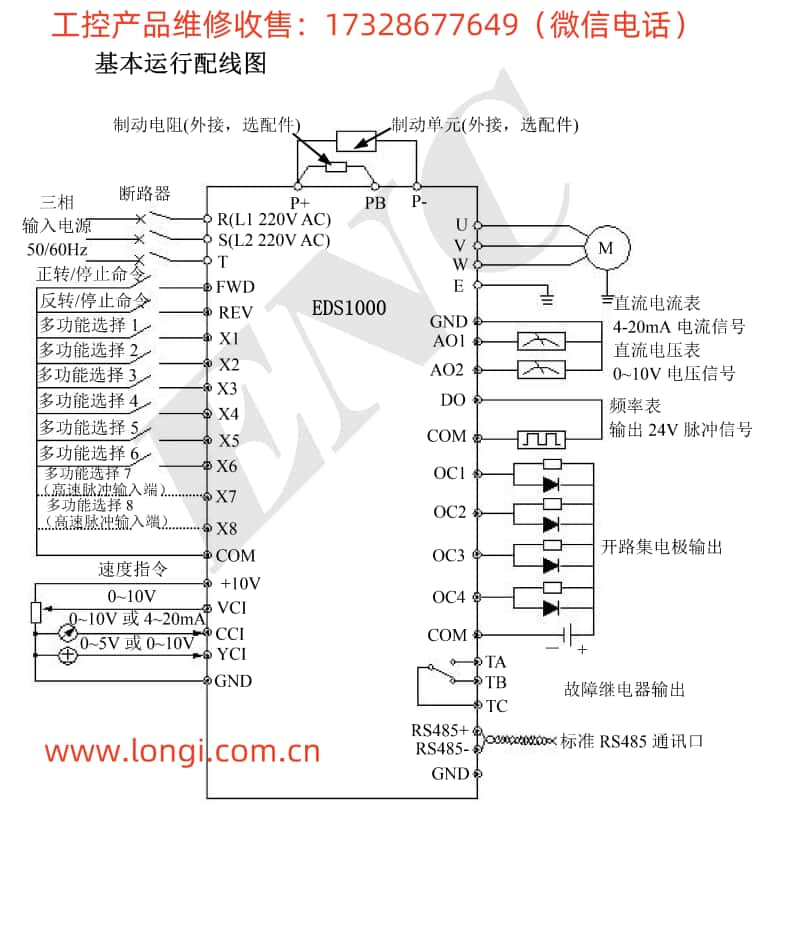
Terminal Connection and Settings
To set up external terminal startup and pulse frequency speed adjustment, you need to connect and configure specific terminals:
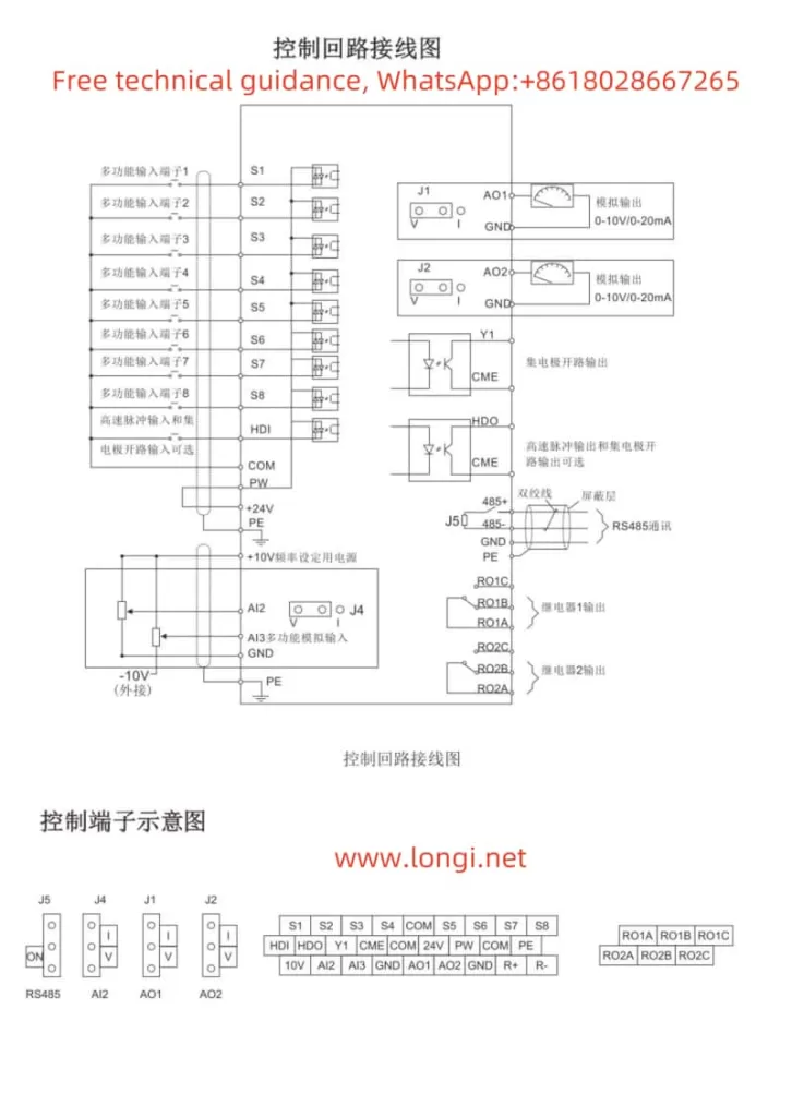
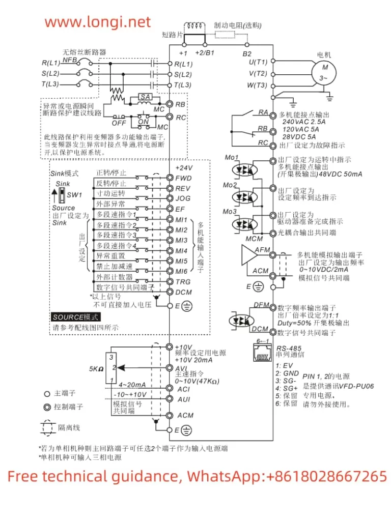
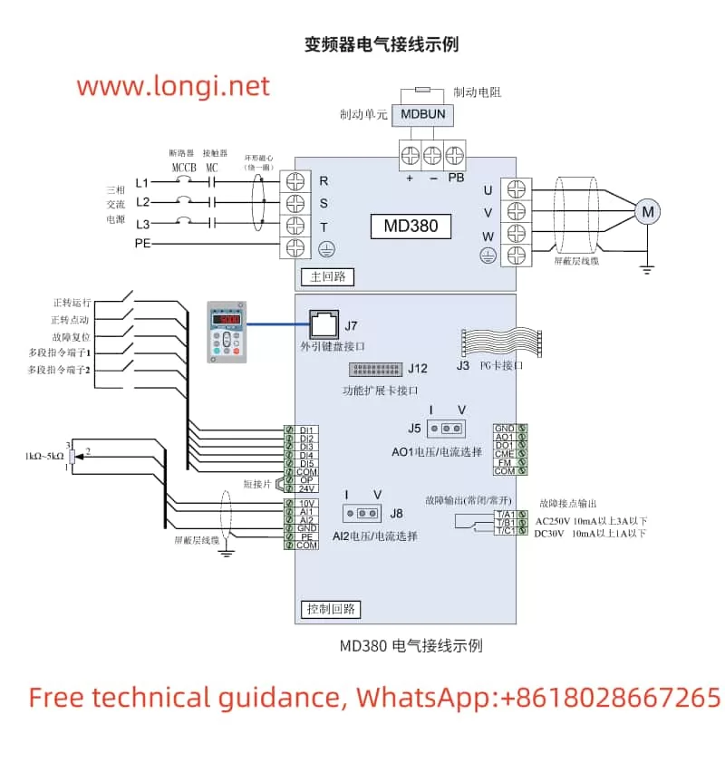
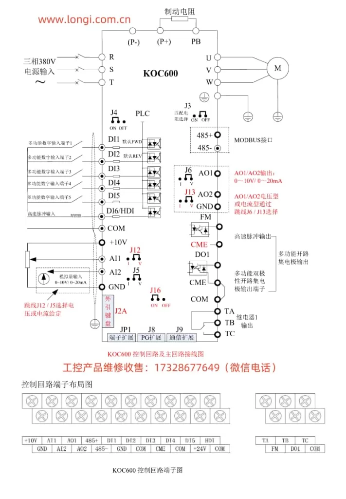
- Connect the external startup terminal: Typically, you would connect an external switch or relay to the
FWD(forward) andREV(reverse) terminals on the inverter. Ensure proper grounding and wiring according to the manual. - Set the command source to terminal control: Navigate to parameter
b0-02and set it to1(Terminal Command Channel). This allows the inverter to receive startup and speed commands from the external terminals. - Configure the pulse input terminal: If using pulse frequency for speed adjustment, connect the pulse generator to the
DI6(High-Speed Pulse Input) terminal. - Set the frequency source to pulse input: Go to parameter
b0-03and set it to5(PULSE pulse setting). This configures the inverter to use the pulse input onDI6as the frequency source. - Adjust pulse-to-frequency parameters: Configure parameters
b5-00tob5-03to define the relationship between the pulse input frequency and the inverter’s output frequency.
Example Configuration Steps
- Connect the external switch to
FWD: Use a normally open switch connected betweenFWDandCOM. - Set the command source:
- Navigate to
b0-02and set it to1.
- Navigate to
- Connect the pulse generator to
DI6: Ensure the pulse generator outputs a compatible voltage and frequency range. - Configure the pulse input:
- Set
b0-03to5(PULSE pulse setting). - Adjust
b5-00to0.00kHz,b5-02to the maximum expected pulse frequency (e.g.,50.00kHz),b5-01to0.0%, andb5-03to100.0%.
- Set
- Save the settings: Press the
DATA/ENTERkey to save all configurations.
By following these steps, you can set up the KCLY INVERTER KOC600 series for external terminal startup and pulse frequency speed adjustment. Always refer to the user manual for detailed wiring diagrams and additional configuration options.