Posted on Leave a comment

Communication Setup Method for Prolet Controller and Yuanxin Inverter YX3000

In modern industrial automation systems, the communication setup between controllers and inverters is crucial for achieving efficient and stable operation. This article will combine the “Prolet Air Compressor Controller and Inverter Communication Setup Manual” and the “Yuanxin Inverter YX3000 Manual” to provide a comprehensive guide on setting up the communication between the Prolet controller and the Yuanxin Inverter YX3000.

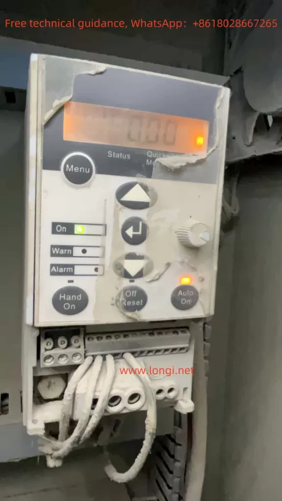
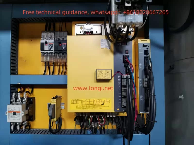
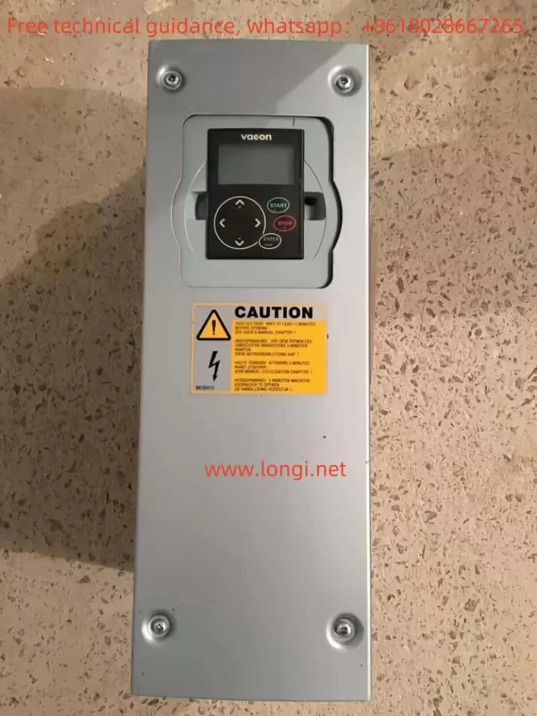
Actual working status of Pulet

1. Communication Protocol Description of Prolet Controller

The Prolet controller adopts a communication protocol that is compatible with industry standards, such as MODBUS RTU. This protocol ensures reliable data transmission between the controller and various devices, including inverters. The key features of the Prolet controller’s communication protocol include:

  • Baud Rate: Typically set at 9600 bps, which is a common baud rate for industrial communication.
  • Parity: No parity bit is used to simplify the communication process and reduce errors.
  • Data Bits: 8 data bits are used to ensure sufficient data transmission capacity.
  • Stop Bits: 1 stop bit is employed to mark the end of each data frame.

To establish communication with the Yuanxin Inverter YX3000, the Prolet controller needs to be configured with the appropriate communication parameters, such as the address of the inverter, baud rate, and data format.

2. Communication Protocol Description of Yuanxin Inverter YX3000

The Yuanxin Inverter YX3000 also supports the MODBUS RTU communication protocol, making it compatible with the Prolet controller. The YX3000 offers a wide range of communication settings to meet different application requirements:

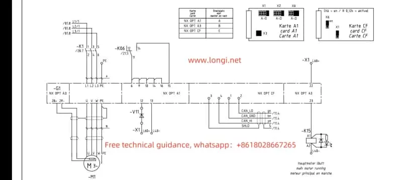
  • Communication Interface: Equipped with standard RS485 communication interfaces, the YX3000 can be easily connected to the Prolet controller using shielded twisted-pair cables.
  • Communication Address: Users can set a unique address for each inverter on the network to facilitate multi-inverter communication.
  • Baud Rate and Data Format: The YX3000 supports various baud rates (e.g., 1200, 2400, 4800, 9600, 19200, 38400 bps) and data formats (e.g., 8N1, 8N2).

To establish communication with the Prolet controller, the YX3000 needs to be configured with the same baud rate, data format, and communication address as the controller.

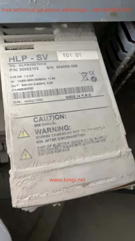
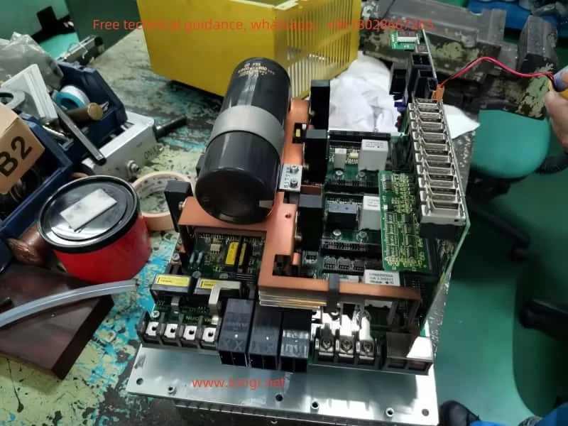
Yuanxin YX3000 physical product

3. Detailed Parameters Required for Communication Between Prolet Controller and YX3000

To set up communication between the Prolet controller and the Yuanxin Inverter YX3000, users need to configure the following detailed parameters on both devices:

  • Communication Address:
    • Prolet Controller: Set the communication address of the YX3000 in the controller’s communication parameters. This address should be unique on the network.
    • YX3000 Inverter: Set the communication address of the inverter to match the address configured in the controller.
  • Baud Rate:
    • Prolet Controller: Set the baud rate to 9600 bps (or other compatible baud rates) in the controller’s communication parameters.
    • YX3000 Inverter: Set the baud rate to 9600 bps (or the same baud rate as the controller) in the inverter’s communication parameters.
  • Data Format:
    • Prolet Controller: Set the data format to 8N1 (8 data bits, no parity, 1 stop bit) in the controller’s communication parameters.
    • YX3000 Inverter: Set the data format to 8N1 (or the same data format as the controller) in the inverter’s communication parameters.
  • Additional Parameters:
    • Prolet Controller: Depending on the specific model and functionality, the controller may require additional communication-related parameters to be configured, such as communication timeout settings, retry intervals, etc.
    • YX3000 Inverter: Similarly, the inverter may also have additional communication parameters that need to be configured, such as communication port settings, communication protocol selection, etc.

After configuring the above parameters, users can test the communication between the Prolet controller and the Yuanxin Inverter YX3000 by sending test commands from the controller and observing the responses from the inverter. If the communication is successful, users can proceed with the integration of the two devices into their industrial automation system.

Posted on Leave a comment

Operation Guide for EURA Inverter E2000 Series User Manual

I. Introduction to Operation Panel Functions and Initialization Settings

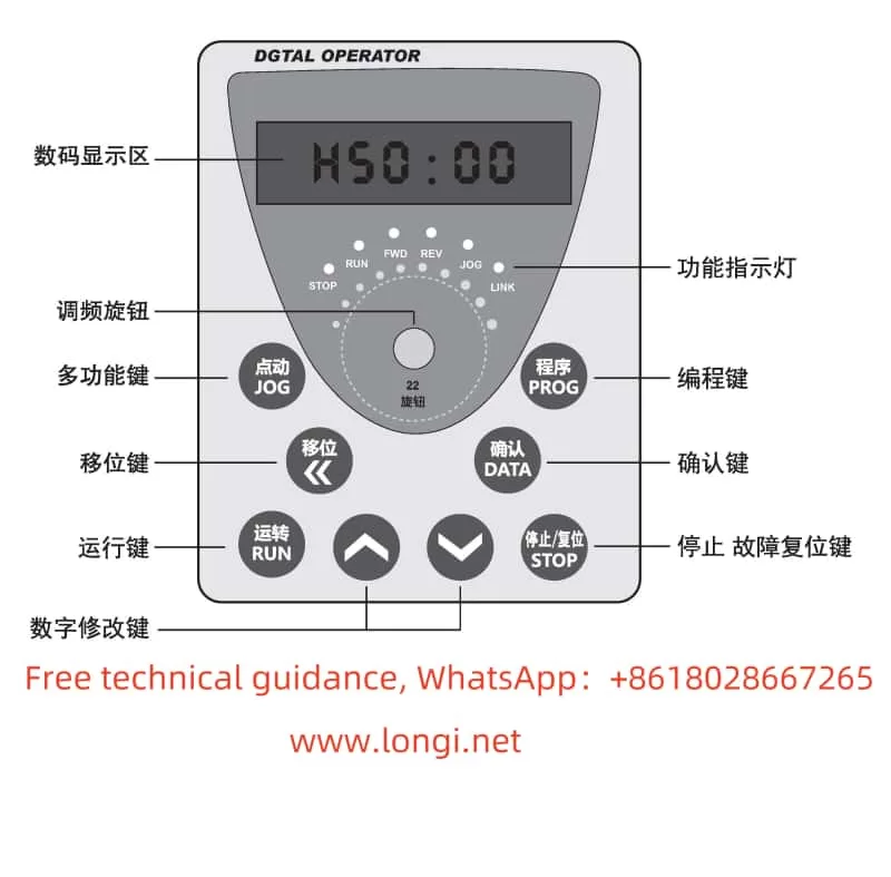
The EURA Inverter E2000 series comes equipped with an intuitive and user-friendly operation panel, enabling users to easily set parameters and monitor the inverter’s status. The operation panel typically includes a display screen, direction keys, function keys, and operation control keys.

Restoring Parameter Initialization Settings:

To restore the inverter’s parameters to their factory settings, users need to enter the programming menu and locate function code F160. The specific steps are as follows:

  1. Press the “Mode” key to display the function codes.
  2. Use the “Up” or “Down” key to select function code F160.
  3. Press the “Set” key to enter the setting value interface for F160.
  4. Change the setting value of F160 to 1 and press the “Set” key again to confirm.

At this point, the inverter will begin the initialization process, restoring all parameters to their factory default values.

Setting Passwords and Parameter Locking:

To ensure the security of parameter settings, the E2000 series inverter supports password protection and parameter locking functions. Users can enable or disable password protection by setting function code F107 and set the user password through F100. Once password protection is enabled, users must enter the correct password before modifying parameters.

Setting Reserved Parameter Areas:

The reserved parameter area allows users to save a set of parameters as a macro for quick recall. Users can select the saved macro by setting function code F135 and restore the user macro through F160.

II. Terminal Control and External Input

Terminal Forward/Reverse Control and External Potentiometer Given:

The E2000 series inverter supports forward/reverse control via terminals and frequency given by an external potentiometer. The specific settings are as follows:

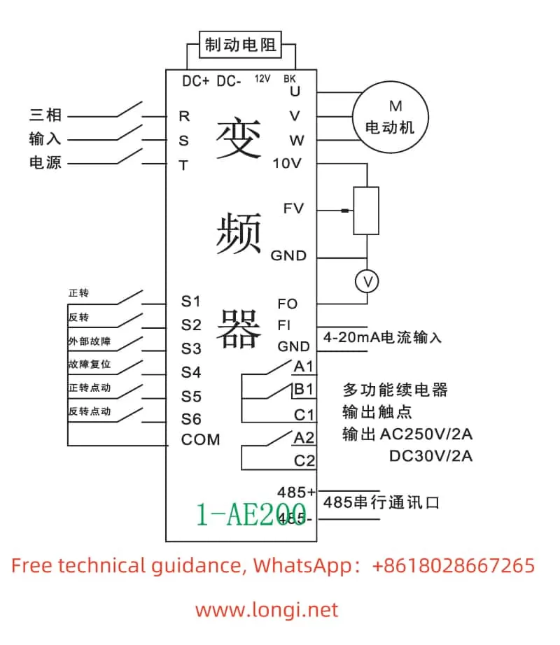
  • Forward/Reverse Control: It is necessary to set function codes F200 and F201 to select terminals as the source of start and stop commands. Simultaneously, set F202 to determine the direction of operation.
  • External Potentiometer Given: It is necessary to set function code F203 to select the main frequency source X and choose analog input AI3 (i.e., external potentiometer) as the given source. Additionally, set F422 to select between panel potentiometer and remote panel potentiometer.

For wiring, users need to connect the output terminal of the external potentiometer to the AI3 terminal of the inverter and ensure proper grounding.

Pulse Input/Output Control:

The E2000 series inverter also supports pulse input/output control, suitable for applications requiring high-precision speed control. Users need to set function codes F440 to F449 to configure pulse input parameters such as minimum frequency, maximum frequency, filter constant, etc. Simultaneously, set F450 to F453 to configure pulse output parameters.

For wiring, users need to connect the output terminal of the pulse generator to the FI terminal of the inverter and connect the FO terminal of the inverter to the device receiving the pulse.

III. Fault Code Analysis and Solutions

The EURA Inverter E2000 series is equipped with a comprehensive fault protection mechanism, capable of real-time monitoring and reporting of various faults. Common fault codes include:

  • OC: Overcurrent protection. Possible causes include motor jam, excessive load, etc. Solutions include checking the motor and load, extending acceleration time, etc.
  • OE: DC overvoltage protection. Possible causes include excessive power supply voltage, brake unit failure, etc. Solutions include checking the power supply voltage, inspecting the brake unit, etc.
  • OL1: Inverter overload protection. Possible causes include excessive load, poor heat dissipation, etc. Solutions include reducing the load, improving heat dissipation conditions, etc.
  • OH: Inverter overheat protection. Possible causes include high ambient temperature, fan failure, etc. Solutions include improving ventilation conditions, replacing the fan, etc.

Users can view fault codes through the operation panel and follow the guidance in the manual for troubleshooting and resolution.

IV. Conclusion

The EURA Inverter E2000 series user manual provides a detailed operation guide covering operation panel function introduction, parameter setting, terminal control, fault troubleshooting, and other aspects. By carefully reading the manual and following the guidance, users can easily achieve the installation, commissioning, and maintenance of the inverter. At the same time, the fault code analysis and solutions in the manual also provide strong support for users, helping them quickly resolve issues that may arise during the operation of the inverter.