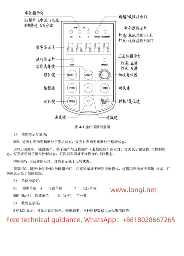
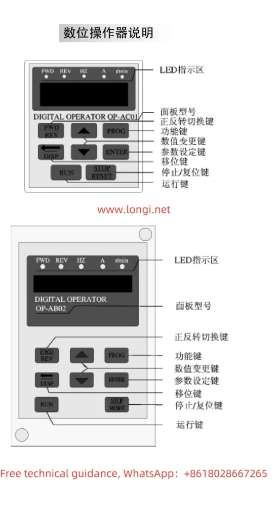
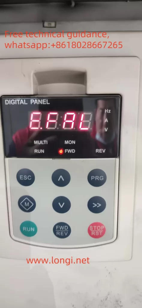
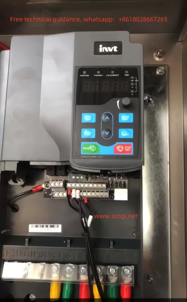
I. Introduction to Inverter Operation Panel Functions and Parameter Initialization
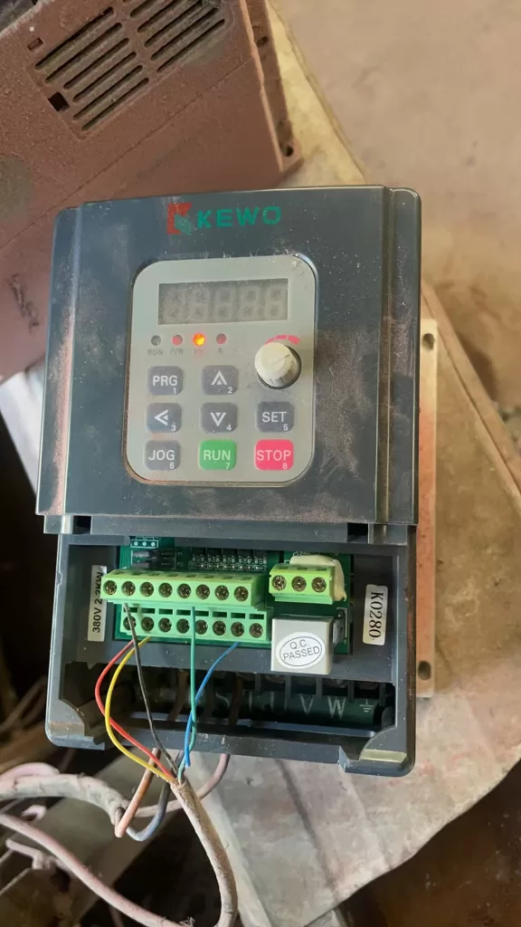
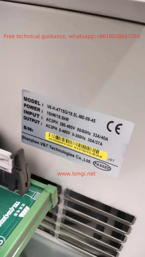
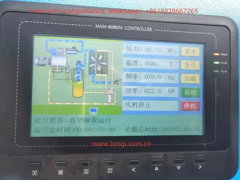
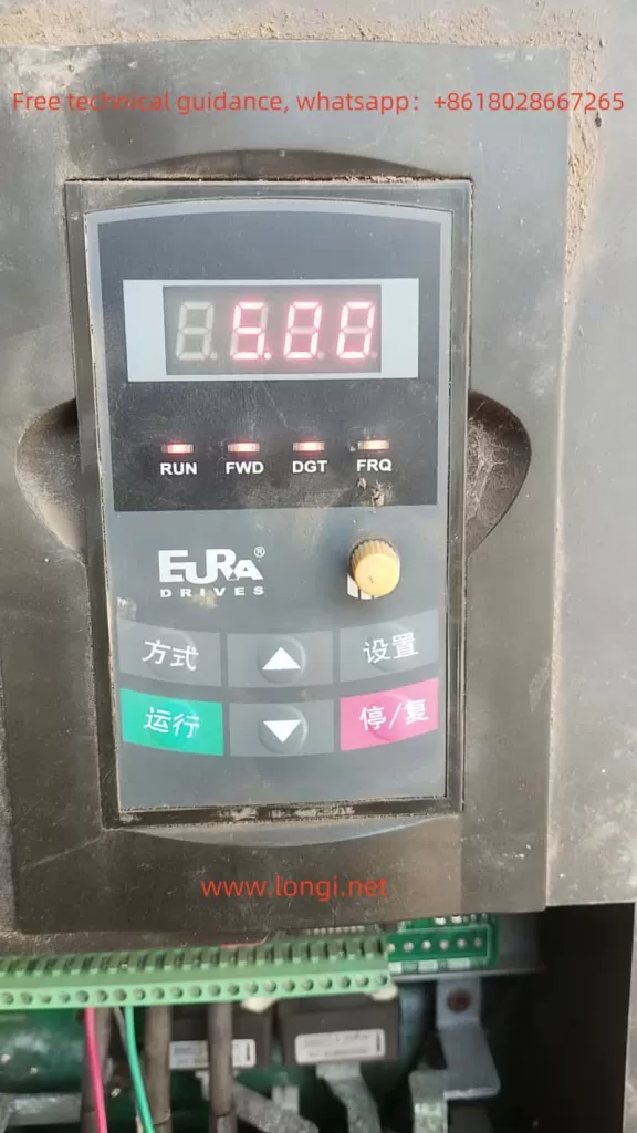
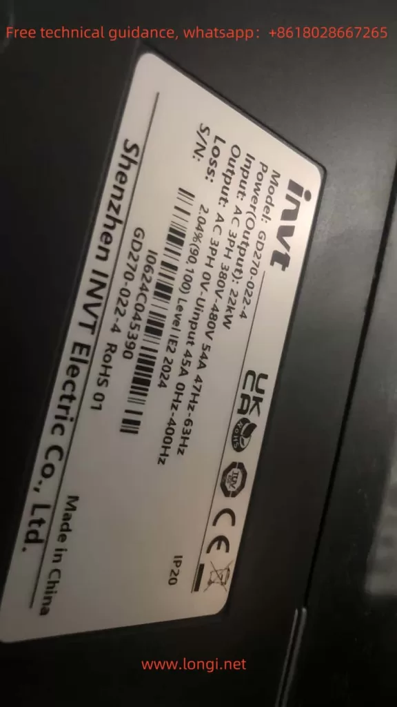
The Inovance GD270 series inverter is an efficient drive specifically designed for fan and pump applications. Its operation panel features a rich set of functions, facilitating user operation and monitoring. The operation panel mainly includes an LED keyboard for displaying the inverter’s operating status, set frequency, and other parameters, as well as for parameter settings and operational control.
Parameter Initialization:
- Press the PRG/ESC button to enter the parameter setting group.
- Use the up and down buttons to select the parameter group or parameter that needs to be initialized.
- Press the DATA/ENT button to enter the next level menu for specific parameter settings.
- Set the parameters that need to be initialized to their factory defaults or desired values.
- After completing the settings, press the PRG/ESC button to return to the initial interface and save the settings.
Setting Password and Parameter Access Restrictions:
- Press the PRG/ESC button to enter the parameter setting group, and use the up and down buttons to navigate to the P07 Human-Machine Interface group.
- Press the DATA/ENT button to enter the next level menu, and use the up and down buttons to navigate to P07.00 User Password (if it’s already set, it doesn’t need adjustment).
- Press the DATA/ENT button to enter the parameter, and use the SHIFT button to shift and set the password (e.g., 02021). Press DATA/ENT to confirm.
- Press the PRG/ESC button twice to return to the initial interface, and wait for 1 minute for the password to take effect.
- Afterward, when pressing the PRG/ESC button to enter the parameter settings again, the user will need to input the previously set password.
- To cancel the password, follow the same steps to enter the P07.00 parameter, set the password to 0, and press DATA/ENT.
Using Fire Crossing Control Function:
The GD270 series inverter supports a fire crossing control function, which can ensure that the inverter continues to operate for a period of time in case of a fire or other emergencies, allowing for safe shutdown or other emergency measures. The specific setup method requires referring to the inverter’s advanced function settings manual and configuring according to actual conditions.
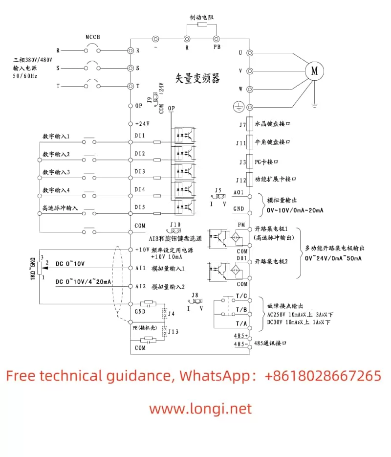
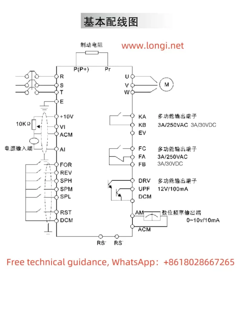
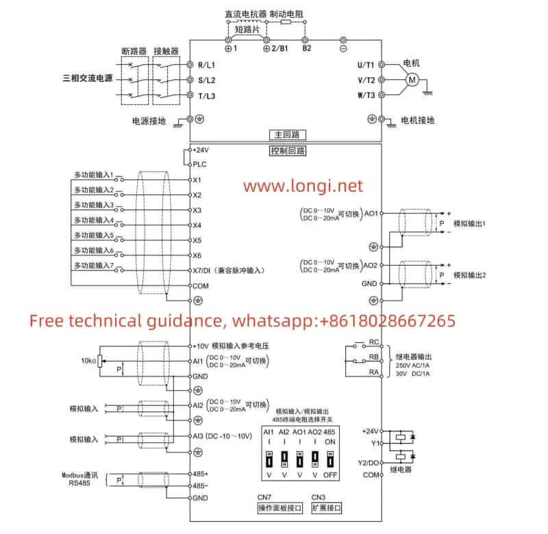
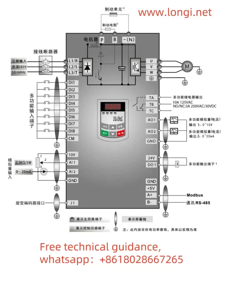
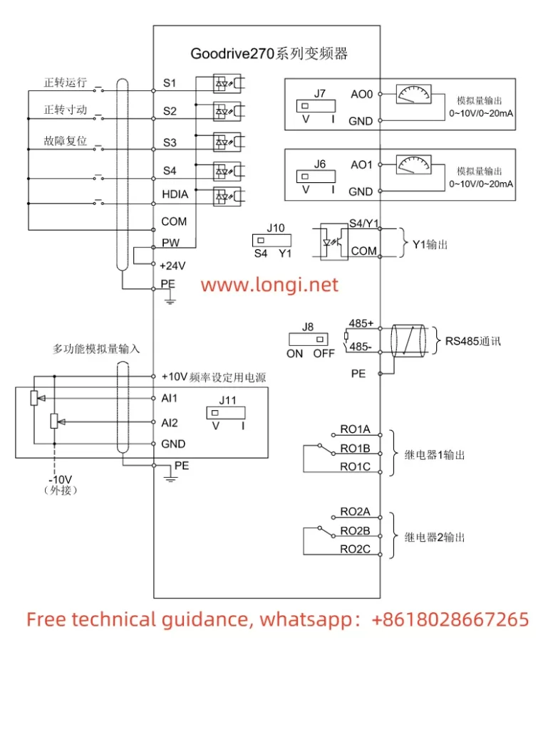
II. Terminal Forward/Reverse Control and External Potentiometer Frequency Speed Regulation
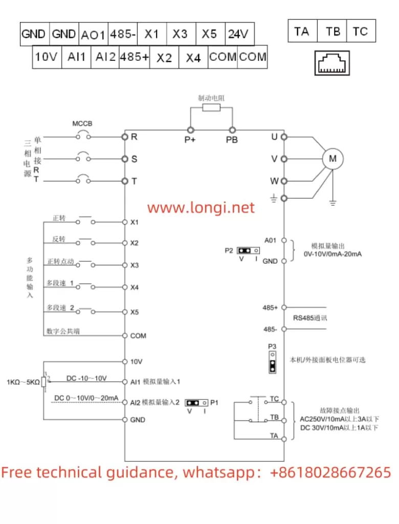
Terminal Forward/Reverse Control:
- Wiring: Connect the multi-function input terminals (such as forward and reverse terminals) to the control signal source (such as buttons, relay outputs, etc.).
- Parameter Settings:
- Enter the parameter setting group and select the control command channel (such as P00.00), setting it to the terminal command channel.
- Set the corresponding function codes for forward and reverse (such as P00.01, P00.02), corresponding to the forward and reverse terminals, respectively.
External Potentiometer Frequency Speed Regulation:
- Wiring: Connect the output terminal (V terminal) of the potentiometer to the analog voltage input terminal of the inverter (such as AI1), and connect the common terminal (GND terminal) of the potentiometer to the common ground terminal of the inverter.
- Parameter Settings:
- Enter the parameter setting group and select the frequency setting selection (such as P01.00), setting it to external terminal given.
- Set the parameters corresponding to the analog voltage input (such as P01.01), selecting the AI1 terminal.
- Adjust other relevant parameters as needed, such as the analog voltage input range and frequency upper limit.
III. Fault Codes and Handling Methods
The GD270 series inverter’s fault code system is quite comprehensive, covering numerous potential issues. The following lists some common fault codes, their meanings, and handling methods:
- OL (Overload): Indicates that the inverter’s output current exceeds the rated current. Handling methods include checking if the load is too heavy, if the motor is jammed, if the parameter settings are reasonable, etc.
- E7 (Encoder Signal Loss): Indicates that the inverter has not received an encoder signal. Handling methods include checking if the encoder connection is good, if the encoder is damaged, etc.
- E8 (Fan Fault): Indicates that the inverter’s internal fan has failed. Handling methods include checking if the fan is operating normally, if the fan connection is good, etc.
- OC (Overcurrent): Indicates that the inverter’s output current exceeds the allowable value. Handling methods include checking if the load is too heavy, if the motor is jammed, if the power supply voltage is too high or too low, etc.
For other fault codes not explicitly stated, such as 5P1, further technical support or detailed user manuals may be required for interpretation. When handling faults, it is essential to understand the inverter’s various parameter settings and operating status to accurately diagnose the fault cause and take appropriate measures.
IV. Conclusion
The Inovance GD270 series inverter is a powerful and easy-to-operate product. Through this guide, users can better understand the inverter’s operation panel functions, parameter setting methods, terminal wiring and parameter configuration, as well as fault code handling and other aspects. In practical applications, users should choose appropriate control methods, parameter settings, and fault handling methods based on specific conditions to ensure the inverter’s normal operation and efficient energy saving. At the same time, it is recommended that users regularly consult the inverter’s user manual and related technical documents to obtain the latest product information and technical support.