Posted on Leave a comment

V&T Inverter V5-H Manual Usage Guide

I. Introduction to the Operation Panel Functions and Parameter Management

1.1 Introduction to the Operation Panel Functions

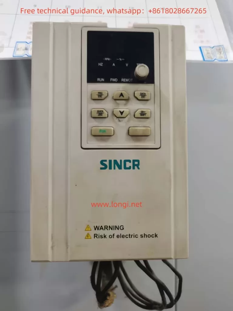
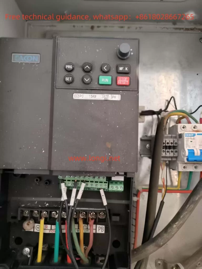
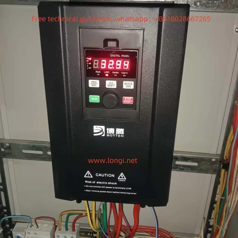
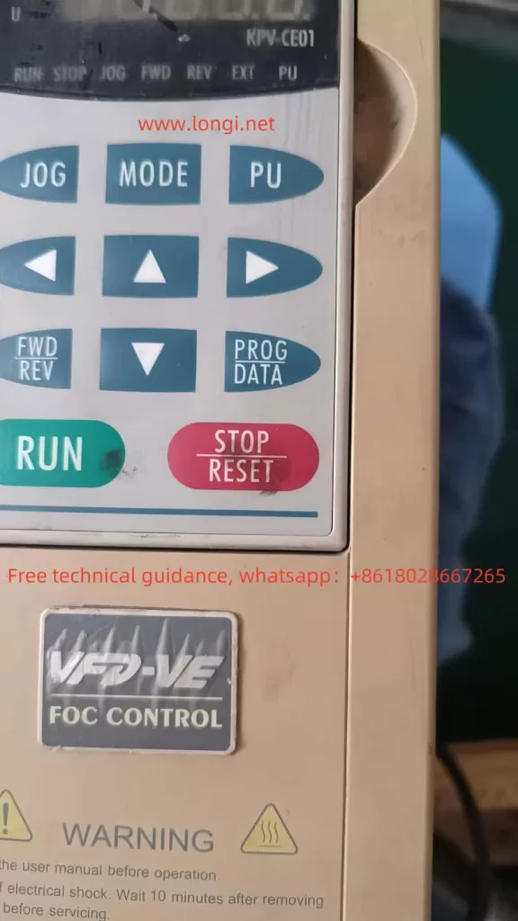
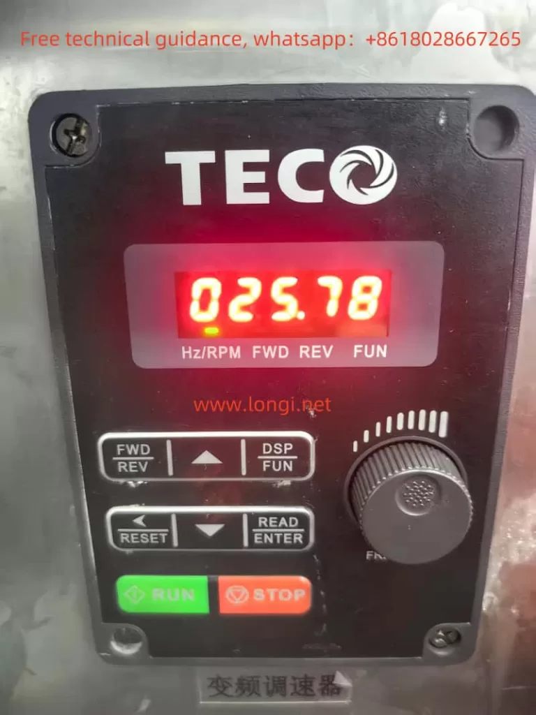
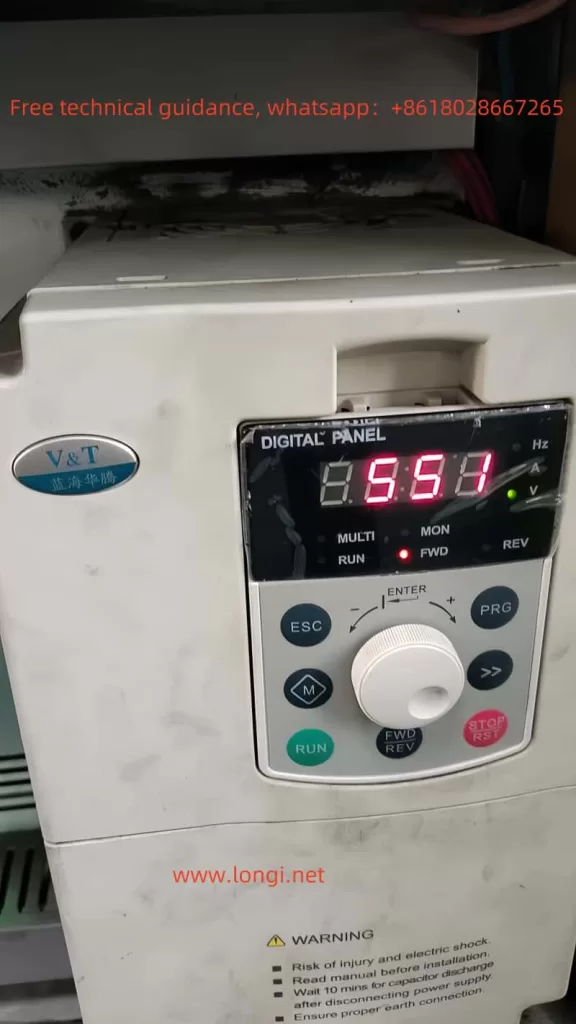
The V&T Inverter V5-H from Blue Ocean Huateng boasts an intuitive and easy-to-use operation panel that offers a wealth of control functions. The operation panel comes in two types: button-type and joystick-type, allowing users to choose based on their actual needs. The indicator lights on the operation panel provide a clear display of the current status of the inverter, such as frequency, current, voltage, and other parameters. Through keys like PRG (program key), ESC (exit key), and the rotary knob (+, -), users can conveniently access various menus for data setting and viewing.

Front image of V5-H

1.2 Parameter Copy

The parameter copy function allows users to quickly replicate the parameters of one inverter to another, significantly improving setup efficiency. The specific operation steps are as follows:

  1. Connect the Operation Panel: Use the operation panel cable to connect the source inverter and the target inverter.
  2. Upload Parameters: On the source inverter, enter the operation panel menu, select the parameter upload function, and upload the parameters to the operation panel.
  3. Download Parameters: Connect the operation panel to the target inverter, select the parameter download function, and download the parameters from the operation panel to the target inverter.

1.3 Restore Parameter Initialization Settings

Restoring the parameter initialization settings can revert all parameters of the inverter to their factory defaults, making it convenient for users to reconfigure the parameters. The specific operation steps are as follows:

  1. Enter the operation panel menu and locate the “Function Code Protection” parameter (P0.01).
  2. Set P0.01 to “2”, then press the confirm key, and the inverter will restore all parameters except motor group parameters (P9 group) to their factory settings.

1.4 Set and Clear Passwords

To protect the inverter parameters from unauthorized modifications, users can set a password. The specific operation steps are as follows:

  1. Set Password: Enter the operation panel menu, locate the “User Password” parameter (P0.00), and set the same password twice consecutively to successfully set the password.
  2. Verify Password: Enter P0.00 again, input the correct password, and you will be able to access the parameter area protected by the password.
  3. Clear Password: After verifying the password, set P0.00 to “0000” to clear the password.

1.5 Set Parameter Access Restrictions

By setting parameter access restrictions, users can control the operation permissions of different users on the inverter. The specific operation steps are as follows:

  1. Enter the operation panel menu and locate the “Function Code Protection” parameter (P0.01).
  2. Set P0.01 to the desired value according to your needs, such as “1” to prohibit changes to all parameters, or “3” to restore all parameters except motor group parameters to their factory settings.

II. External Control and Speed Adjustment Settings

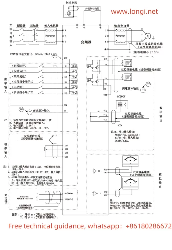
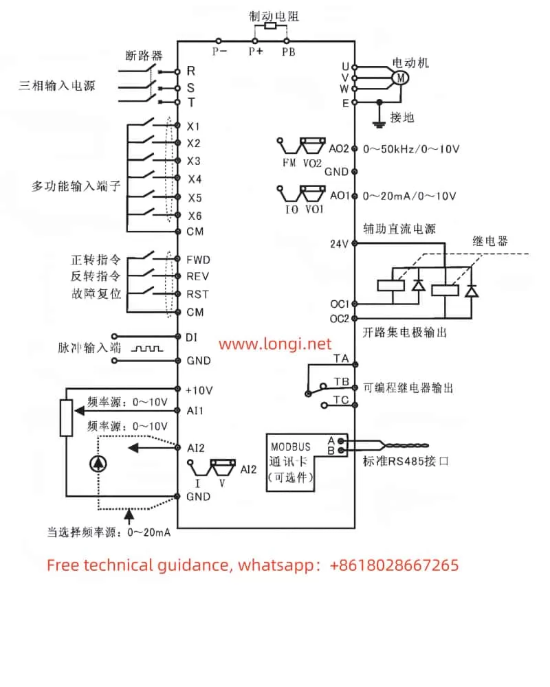
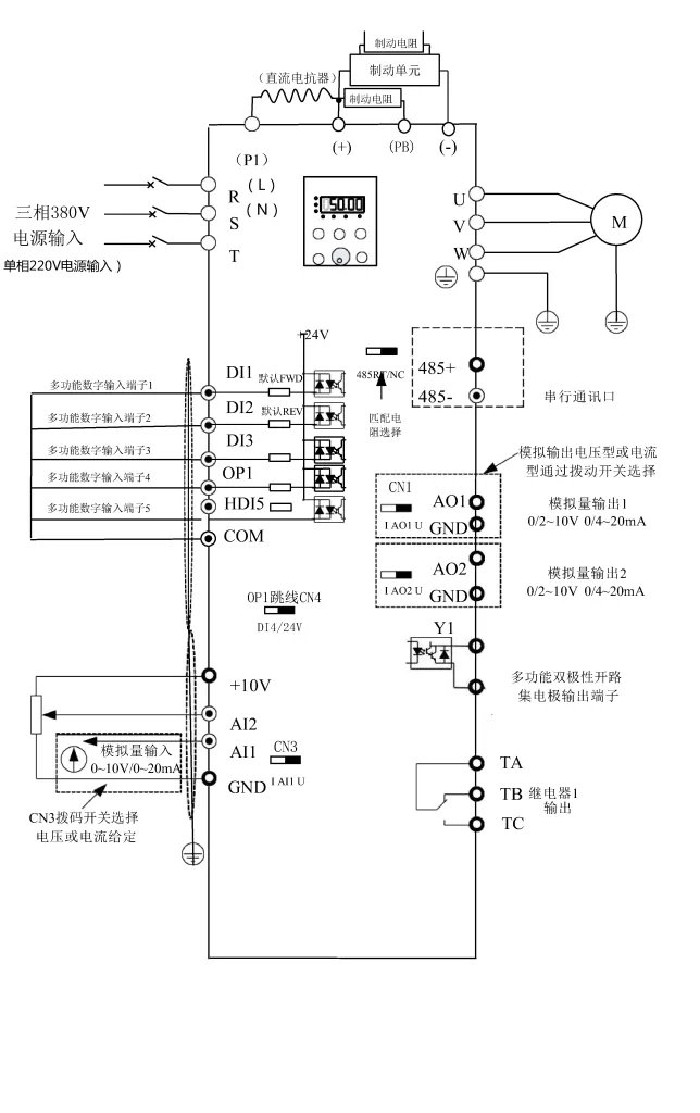
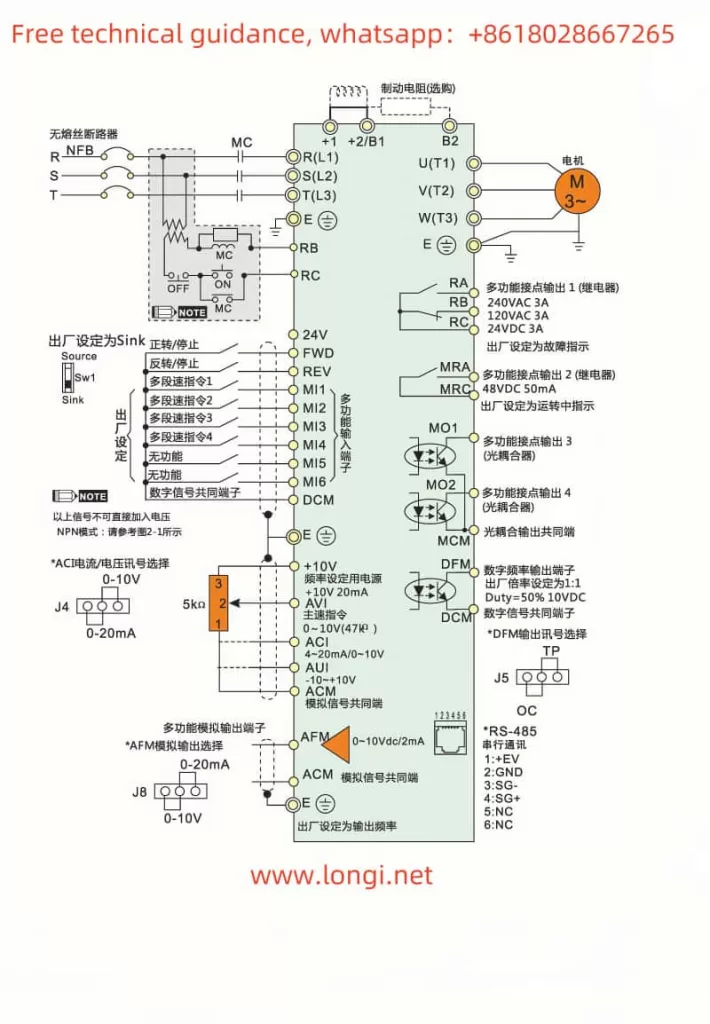
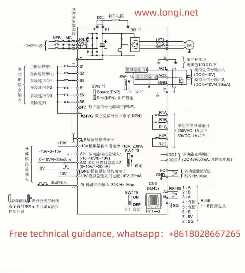
2.1 External Terminal Forward and Reverse Control

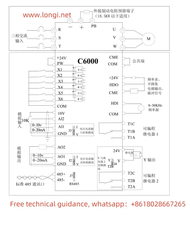
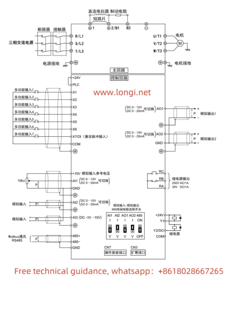
The V&T Inverter V5-H supports forward and reverse control of the motor through external terminals. Users need to connect the FWD (forward) and REV (reverse) terminals to the control signal source, such as a PLC or button switch. At the same time, corresponding parameters need to be set in the inverter:

  1. Enter the operation panel menu and locate the “Run Command Given Mode” parameter (P0.06).
  2. Set P0.06 to “1”, indicating that the run command is given through terminals.

2.2 External Potentiometer Given Frequency Speed Regulation

By connecting an external potentiometer to the AI1 (Analog Input 1) terminal of the inverter, users can achieve speed control of the motor frequency. The specific steps are as follows:

  1. Wiring: Connect the output terminal of the external potentiometer to the AI1 terminal of the inverter, and connect the COM terminal of AI1 to the common terminal of the inverter.
  2. Parameter Setting:
    • Enter the operation panel menu and locate the “Open-Loop Main Given Mode” parameter (P0.04).
    • Set P0.04 to “1”, indicating that the frequency is given by AI1 analog input.
    • Set the AI1 analog input curve (P6.00) as needed to achieve linear or nonlinear speed regulation.
V5-H standard wiring diagram

III. Fault Codes and Solutions

The V&T Inverter V5-H features a comprehensive fault diagnosis function that can display fault codes and fault information in real-time, helping users quickly locate problems. The following are some common fault codes, their meanings, and solutions:

3.1 E.oc1: Overcurrent Protection During Acceleration

Meaning: The inverter detects an overcurrent phenomenon during acceleration.

Solution:

  • Check if the grid voltage is too low.
  • Extend the acceleration time to reduce load mutation.
  • Check if the motor parameter settings are correct.
  • Consider replacing with a higher-power inverter.

3.2 E.oc2: Overcurrent Protection During Deceleration

Meaning: The inverter detects an overcurrent phenomenon during deceleration.

Solution:

  • Extend the deceleration time.
  • Use a suitable energy dissipation braking component.
  • Check the motor parameter settings.

3.3 E.AUt: Self-Tuning Fault

Meaning: The inverter encounters a fault during self-tuning.

Solution:

  • Ensure that the motor is in a stationary state before performing self-tuning.
  • Check if the motor wires are properly connected and within the specified length.
  • Reset the P9 group motor parameters according to the motor nameplate.

3.4 E.oL2: Motor Overload Protection

Meaning: The inverter detects motor overload.

Solution:

  • Check if the load is too heavy or if the motor is jammed.
  • Adjust the inverter overload protection parameters (P9.16, P9.18).
  • Check if the motor is overheating, and replace it if necessary.

IV. Conclusion

The V&T Inverter V5-H manual provides users with detailed operation guides and troubleshooting methods. By mastering the functions of the operation panel and parameter setting methods, users can conveniently control and manage the inverter. At the same time, understanding common fault codes and their solutions can help users quickly locate and resolve issues, ensuring the stable operation of the inverter. In practical applications, users should also make flexible adjustments and optimizations based on specific needs and site conditions.

Posted on Leave a comment

SINCR C6000 Series User Manual Operation Guide

The SINCR C6000 series is a high-performance variable frequency drive widely used in industrial automation, mechanical processing, petrochemical, and other fields. This article provides a detailed introduction to the operation panel functions, parameter settings, fault resolution, and more for the SINCR C6000 series variable frequency drive, helping users better operate and maintain the device.

Front image of C6000

I. Operation Panel Function Introduction

1. Operation Panel Functions

The operation panel of the SINCR C6000 series variable frequency drive is the primary interface for user interaction, integrating functions such as operation control, parameter settings, and display. The panel features eight buttons with the following functions:

  • PRG/PRG: Program key, used to enter or exit the function code editing mode.
  • DATA/ENT: Enter the next menu or confirm data.
  • A: Increment data.
  • V: Decrement data.
  • SHIFT: Shift key, used to select data bits or cycle through display parameters.
  • RUN: Run key, used to start or stop the variable frequency drive.
  • STOP/RST: Stop/Reset key, used to stop operation or reset faults.
  • QUICK/JOG: Inching key, press and hold for inching operation, release to return to the previous state.

2. How to Copy Parameters to Another Variable Frequency Drive

The SINCR C6000 series supports parameter copying, allowing users to copy the parameter settings from one variable frequency drive to another. The specific steps are as follows:

  1. Enter the parameter setting interface by pressing the PRG key, select function code F0.18, and set it to 1 (restore factory settings).
  2. Export the parameters to a storage device (such as a USB drive), following the specific method in the variable frequency drive operation manual.
  3. Insert the storage device into the target variable frequency drive, enter the parameter setting interface, select the parameter import function, and import the parameters into the target variable frequency drive.
  4. After completing the parameter import, press the PRG key to exit the parameter setting interface.

3. How to Restore Parameter Initialization Settings

When the variable frequency drive encounters a fault or needs to be reconfigured, the parameter initialization settings can be restored. The specific steps are as follows:

  1. Press the PRG key to enter the function code editing mode.
  2. Select function code F0.18 and set it to 1 (restore factory settings).
  3. Press the ENT key to confirm the restoration of factory settings.
  4. The variable frequency drive will automatically restore to the factory settings. After completion, press the PRG key to exit.

4. How to Set and Remove Passwords

To prevent unauthorized personnel from operating the variable frequency drive, a password protection feature can be set. The specific steps are as follows:

  1. Press the PRG key to enter the function code editing mode.
  2. Select function code F7.00 and enter a password (range: 0~65535).
  3. Press the ENT key to confirm the password setting.

To remove the password, follow these steps:

  1. Press the PRG key to enter the function code editing mode.
  2. Select function code F7.00 and set the password to 0.
  3. Press the ENT key to confirm the removal of the password.

5. How to Set Parameter Access Restrictions

To prevent unauthorized personnel from modifying the variable frequency drive parameters, parameter access restrictions can be set. The specific steps are as follows:

  1. Press the PRG key to enter the function code editing mode.
  2. Select function code F7.00 and enter a password (range: 0~65535).
  3. Press the ENT key to confirm the password setting.
  4. After setting, the variable frequency drive will require a password to enter the parameter setting interface.
C6000 standard wiring diagram

II. External Terminal Control and Speed Adjustment

1. External Terminal Forward and Reverse Control

The SINCR C6000 series supports forward and reverse control through external terminals. The specific wiring and parameter settings are as follows:

Wiring:

  • X1 Terminal: Forward control, connect to run forward, disconnect to stop.
  • X2 Terminal: Reverse control, connect to run reverse, disconnect to stop.

Parameter Settings:

  1. Press the PRG key to enter the function code editing mode.
  2. Select function code F5.01 and set it to 1 (forward operation).
  3. Select function code F5.02 and set it to 2 (reverse operation).
  4. Press the ENT key to confirm the parameter settings.

2. External Potentiometer Speed Adjustment

The SINCR C6000 series supports speed adjustment through an external potentiometer. The specific wiring and parameter settings are as follows:

Wiring:

  • AI1 Terminal: Analog input terminal, connect to the output signal of the external potentiometer.

Parameter Settings:

  1. Press the PRG key to enter the function code editing mode.
  2. Select function code F0.02 and set it to 1 (analog AI1 setting).
  3. Select function code F5.09 and set the lower limit value for the AI1 terminal (range: 0.00V~10.00V).
  4. Select function code F5.10 and set the lower limit corresponding to the AI1 terminal setting (range: -100.0%~100.0%).
  5. Select function code F5.11 and set the upper limit value for the AI1 terminal (range: 0.00V~10.00V).
  6. Select function code F5.12 and set the upper limit corresponding to the AI1 terminal setting (range: -100.0%~100.0%).
  7. Press the ENT key to confirm the parameter settings.

III. Fault Codes and Solutions

The SINCR C6000 series variable frequency drive may encounter various faults during operation, which are indicated by fault codes. Below are common fault codes, their meanings, and solutions:

1. Fault Codes and Meanings

  • Err01: Inverter unit U phase protection.
  • Err02: Inverter unit V phase protection.
  • Err03: Inverter unit W phase protection.
  • Err04: Acceleration overcurrent.
  • Err05: Deceleration overcurrent.
  • Err06: Constant speed overcurrent.
  • Err07: Acceleration overvoltage.
  • Err08: Deceleration overvoltage.
  • Err09: Constant speed overvoltage.
  • Err10: Bus undervoltage fault.
  • Err11: Motor overload.
  • Err12: Variable frequency drive overload.
  • Err13: Input phase loss.
  • Err14: Output phase loss.
  • Err15: Rectifier block overheating.
  • Err16: Inverter module overheating fault.
  • Err17: External fault.
  • Err18: Communication fault.
  • Err19: Current detection fault.
  • Err20: Motor self-learning fault.
  • Err21: EEPROM operation fault.
  • Err22: PID feedback disconnection fault.
  • Err23: Braking unit fault.

2. Fault Solutions

Err01~Err03 (Inverter Unit Protection):

  • Cause: Overheating or short circuit in the inverter unit.
  • Solution: Check the heat dissipation of the inverter unit, ensure the fan is working properly; check the wiring of the inverter unit, and eliminate short circuit faults.

Err04~Err06 (Overcurrent Protection):

  • Cause: Motor overload or excessive output current from the variable frequency drive.
  • Solution: Reduce the motor load; check the parameter settings of the variable frequency drive to ensure the motor parameters match the variable frequency drive.

Err07~Err09 (Overvoltage Protection):

  • Cause: Input voltage is too high or parameter settings are incorrect.
  • Solution: Check if the input voltage is within the rated range of the variable frequency drive; adjust the parameter settings to ensure the output voltage is within a reasonable range.

Err10 (Bus Undervoltage Fault):

  • Cause: Input voltage is too low.
  • Solution: Check if the input voltage is within the rated range of the variable frequency drive; ensure the input power supply is stable.

Err11 (Motor Overload):

  • Cause: Motor load is too high.
  • Solution: Reduce the motor load; check if the motor parameters match the variable frequency drive.

Err12 (Variable Frequency Drive Overload):

  • Cause: Excessive output current from the variable frequency drive.
  • Solution: Reduce the motor load; check the parameter settings of the variable frequency drive to ensure the motor parameters match the variable frequency drive.

Err13~Err14 (Phase Loss Protection):

  • Cause: Phase loss in the input or output power supply.
  • Solution: Check the wiring of the input or output power supply; ensure the power supply is normal.

Err15~Err16 (Overheating Protection):

  • Cause: Overheating of the rectifier block or inverter module.
  • Solution: Check if the cooling fan is working properly; ensure the heat dissipation path of the variable frequency drive is unobstructed.

Err17 (External Fault):

  • Cause: Fault in external equipment.
  • Solution: Check the wiring and operation status of the external equipment, and eliminate external faults.

Err18 (Communication Fault):

  • Cause: Communication line fault or incorrect communication parameter settings.
  • Solution: Check if the communication line is normal; adjust the communication parameter settings to ensure normal communication.

Err19 (Current Detection Fault):

  • Cause: Current sensor fault.
  • Solution: Check the wiring and operation status of the current sensor, and eliminate sensor faults.

Err20 (Motor Self-Learning Fault):

  • Cause: Motor parameter self-learning failure.
  • Solution: Check if the motor parameter settings are correct; perform motor parameter self-learning again.

Err21 (EEPROM Operation Fault):

  • Cause: EEPROM memory fault.
  • Solution: Replace the EEPROM memory.

Err22 (PID Feedback Disconnection Fault):

  • Cause: PID feedback line disconnection.
  • Solution: Check the wiring and operation status of the PID feedback line, and eliminate disconnection faults.

Err23 (Braking Unit Fault):

  • Cause: Braking unit fault.
  • Solution: Check the wiring and operation status of the braking unit, and eliminate braking unit faults.

Conclusion

The SINCR C6000 series is a powerful and easy-to-operate variable frequency drive. Through reasonable parameter settings and correct operation, precise control and efficient speed adjustment of the motor can be achieved. This article provides a detailed introduction to the operation panel functions, parameter settings, and fault resolution of the variable frequency drive, aiming to help users better operate and maintain the device. If problems are encountered during use, it is recommended to refer to the variable frequency drive user manual or contact the manufacturer’s technical support to ensure the normal operation and long-term stability of the device.

Posted on Leave a comment

Analysis and Solutions for the Uu1 Fault in Yaskawa J1000 Series Inverters

The Yaskawa J1000 series inverters are widely used in industrial automation for their stable control performance and high energy efficiency. However, during actual operation, inverters may encounter various faults, one of which is the “Uu1” fault. This article will analyze the meaning, causes, and solutions for the Uu1 fault from both external and internal perspectives, providing a reference for inverter maintenance and repair.


J1000 displays Uu1 fault

I. Meaning and Causes of the Uu1 Fault

1. Fault Meaning

The Uu1 fault indicates an undervoltage output fault, meaning the inverter detects that the output voltage is below the set minimum value, triggering a protective mechanism. This fault often causes the inverter to stop, protecting the motor and load from potential damage.

2. Causes of the Fault

The Uu1 fault can be attributed to several factors:

  • Unstable power supply: The input voltage to the inverter is lower than the rated range, leading to insufficient output voltage.
  • Wiring issues: Poor contact in the input or output wiring causes voltage drops.
  • Internal inverter faults: Damage to the inverter’s internal circuits or components results in abnormal output voltage.
  • Motor or load faults: Issues with the motor or load cause abnormal feedback voltage.

3. On-Site Handling Methods

To address the Uu1 fault on-site, follow these steps:

  1. Check the power supply voltage: Use a voltmeter to measure the inverter’s input voltage and ensure it is within the rated range. If the voltage is too low or unstable, inspect the power supply, and replace it or use a voltage stabilizer if necessary.
  2. Inspect the wiring: Check the input and output wiring for proper contact, ensuring no loose or disconnected wires. If poor contact is found, reconnect the wiring and tighten the screws.
  3. Examine the inverter internally: If the power supply and wiring are fine, the issue may lie within the inverter. Consult a professional technician or the manufacturer for repairs.
  4. Check the motor and load: Ensure the motor is operating normally and inspect the load for any issues.
  5. Reset the fault: After resolving the issue, press the RESET button on the inverter to clear the fault. Restart the inverter and observe its operation.

II. Analysis of Electrical Issues from the Inverter’s Internal Structure

1. Overview of the Inverter’s Internal Structure

The internal structure of the Yaskawa J1000 series inverter primarily includes the rectifier circuit, inverter circuit, control circuit, and protection circuit. The rectifier circuit converts AC voltage to DC voltage, the inverter circuit converts DC voltage to variable-frequency AC voltage, the control circuit regulates the output frequency and voltage, and the protection circuit detects and protects against faults such as overload, overvoltage, and overcurrent.

2. Electrical Issues Related to the Uu1 Fault

The Uu1 fault is typically associated with the inverter’s output circuit and involves the following aspects:

  • Rectifier circuit faults: Damage to diodes or capacitors in the rectifier circuit can lead to insufficient DC voltage, affecting the output voltage.
  • Inverter circuit faults: Damage to IGBT modules or driver circuits in the inverter circuit can cause abnormal output voltage.
  • Control circuit faults: Faults in the microprocessor or driver chips in the control circuit can result in inaccurate output voltage regulation.
  • Protection circuit faults: Malfunctioning detection components or protection chips in the protection circuit can lead to incorrect identification of undervoltage.

3. Electrical Repair Methods

To repair the Uu1 fault, follow these steps:

  1. Inspect the rectifier circuit: Use a multimeter to test the diodes and capacitors in the rectifier circuit to ensure they are functioning correctly. Replace any damaged components.
  2. Check the inverter circuit: Inspect the IGBT modules and driver circuits for proper operation. Replace any faulty modules or chips.
  3. Examine the control circuit: Test the microprocessor and driver chips to ensure they are functioning correctly. Replace any faulty chips.
  4. Inspect the protection circuit: Check the detection components and protection chips in the protection circuit for proper operation. Replace any faulty components.

J1000 physical image

III. Comprehensive Solutions for the Uu1 Fault

1. Preventive Measures

To prevent the occurrence of the Uu1 fault, consider the following measures:

  • Regularly check the power supply voltage: Periodically inspect the inverter’s input voltage to ensure stability.
  • Maintain wiring connections: Regularly check the wiring for proper contact and address any issues promptly.
  • Inspect the inverter internally: Periodically check the inverter’s internal circuits to identify and resolve potential faults early.
  • Maintain the motor and load: Regularly inspect the motor and load to ensure they are operating correctly.

2. Fault Handling Procedure

When addressing the Uu1 fault, follow this procedure:

  1. Confirm the fault: Verify the Uu1 fault on the inverter’s display.
  2. Check the power supply voltage: Ensure the input voltage is normal.
  3. Inspect the wiring: Check for proper wiring connections.
  4. Examine the inverter internally: Ensure the internal circuits are functioning correctly.
  5. Check the motor and load: Verify that the motor and load are operating normally.
  6. Reset the fault: After resolving the issue, reset the inverter and observe its operation.

3. Professional Support

If the Uu1 fault cannot be resolved through the above methods, consult a professional technician or the manufacturer for further assistance.


Conclusion

The Uu1 fault in the Yaskawa J1000 series inverters is a common undervoltage output fault with complex causes, involving the power supply, wiring, internal circuits, motor, and load. Through systematic fault analysis and step-by-step troubleshooting, the Uu1 fault can be effectively resolved, ensuring stable inverter operation. Regular maintenance and preventive measures are also crucial in avoiding such faults.

Posted on Leave a comment

EACON Inverter EC590 User Manual Operation Guide

I. Introduction to the Operation Panel Functions and Parameter Management

1.1 Introduction to the Operation Panel Functions

The operation panel of the EACON Inverter EC590 consists of LED digital displays, LEDs, and function buttons, capable of displaying the inverter’s operating status, frequency, current, voltage, and other parameters. The main buttons on the panel include RUN, STOP/RESET, PRG/SET, and MF.K (multi-function key). Through the operation panel, users can conveniently perform parameter settings, monitor operating status, reset faults, and other operations.

EC590 front image

1.2 Copying Parameters to Another Inverter

To copy the parameters from one EACON Inverter EC590 to another, follow these steps:

  1. Ensure Identical Model Numbers: The premise for copying parameters is that both inverters must be of the same model to ensure parameter compatibility.
  2. Enter Parameter Copy Mode: On one inverter, press the PRG/SET button to enter the parameter setting mode, locate and set parameter FP-00 to a non-zero value (e.g., 1234) to enable the parameter copy function.
  3. Connect the Communication Cable: Use a dedicated communication cable to connect the communication interfaces of both inverters.
  4. Initiate the Copy Process: On the source inverter, press and hold the MF.K button for several seconds until the panel displays “COPY,” indicating that the copy process has started. At this time, the target inverter should be in standby mode.
  5. Complete the Copy: Once the copy process is complete, the source inverter’s panel will display “END,” indicating that the parameters have been successfully copied to the target inverter. At this point, the communication cable can be disconnected, and the FP-00 parameters of both inverters set to 0 to disable the parameter copy function.

1.3 Initializing Parameters

To initialize the parameters of the EACON Inverter EC590, follow these steps:

  1. Enter Parameter Setting Mode: Press the PRG/SET button to enter the parameter setting mode.
  2. Locate Initialization Parameter: In the parameter list, find parameter FP-01, which controls parameter initialization.
  3. Set Initialization Parameter: Set parameter FP-01 to 1 and press the MF.K button to confirm. At this point, the inverter will display “INIT,” indicating that the initialization process has started.
  4. Complete Initialization: After initialization is complete, the inverter will automatically restart. Upon restart, all parameters will be restored to their factory defaults.

1.4 Setting and Removing Passwords

Setting a Password

  1. Enter Parameter Setting Mode: Press the PRG/SET button to enter the parameter setting mode.
  2. Locate Password Setting Parameter: In the parameter list, find parameter FP-00, which is used to set the password.
  3. Set the Password: Set parameter FP-00 to the desired password value (e.g., 1234) and press the MF.K button to confirm. At this point, the password is set.

Removing a Password

  1. Enter Parameter Setting Mode: Press the PRG/SET button to enter the parameter setting mode.
  2. Locate Password Setting Parameter: In the parameter list, find parameter FP-00.
  3. Remove the Password: Set parameter FP-00 to 0 and press the MF.K button to confirm. At this point, the password is removed.

1.5 Setting Parameter Access Restrictions

The EACON Inverter EC590 provides a parameter access restriction function, which can be controlled by setting parameter FP-02 to control the display and modification permissions of different parameter groups.

  1. Enter Parameter Setting Mode: Press the PRG/SET button to enter the parameter setting mode.
  2. Locate Parameter Access Restriction Parameter: In the parameter list, find parameter FP-02.
  3. Set Access Restrictions: Set the value of parameter FP-02 as needed. For example, setting FP-02 to 10 (binary 1010) allows the display of U and A group parameters but prohibits modification.

II. External Terminal Control and Frequency Speed Regulation

2.1 External Terminal Control for Forward and Reverse Rotation

To achieve forward and reverse rotation control via external terminals, wiring and parameter settings are required as follows:

Wiring

  1. Forward Control: Connect the normally open contacts of an external switch or relay to the S1 and COM terminals of the inverter.
  2. Reverse Control: Connect the normally open contacts of an external switch or relay to the S2 and COM terminals of the inverter.

Setting Parameters

  1. Enter Parameter Setting Mode: Press the PRG/SET button to enter the parameter setting mode.
  2. Set Operation Command Source: Set parameter F0-02 to 1 (terminal control).
  3. Set Terminal Function: Set parameter F4-00 to 1 (S1 terminal for forward rotation) and parameter F4-01 to 2 (S2 terminal for reverse rotation).

2.2 External Potentiometer for Frequency Speed Regulation

To achieve frequency speed regulation via an external potentiometer, wiring and parameter settings are required as follows:

Wiring

  1. Potentiometer Wiring: Connect the three pins of an external potentiometer to the AI1, GND, and +10V terminals of the inverter. Among them, AI1 is the analog input terminal, GND is the grounding terminal, and +10V is the external power supply terminal.

Setting Parameters

  1. Enter Parameter Setting Mode: Press the PRG/SET button to enter the parameter setting mode.
  2. Set Frequency Command Source: Set parameter F0-03 to 4 (AI1 analog input).
  3. Set AI Curve: Set the input curve of AI1 as needed (e.g., parameters F4-13 to F4-16) to determine the relationship between analog input and frequency output.
EC590标准配线图

III. Fault Codes and Solutions

The EACON Inverter EC590 provides a wealth of fault codes to indicate various faults during operation. The following are some common fault codes and their solutions:

3.1 Err02 (Acceleration Overcurrent)

Fault Meaning: Overcurrent occurs during acceleration of the inverter.

Solution:

  1. Check if the motor and load are too large.
  2. Increase the acceleration time (parameter F0-17).
  3. Check if the motor parameters are correctly set.

3.2 Err03 (Deceleration Overcurrent)

Fault Meaning: Overcurrent occurs during deceleration of the inverter.

Solution:

  1. Check if the motor and load are too large.
  2. Increase the deceleration time (parameter F0-18).
  3. Check if the braking unit and braking resistor are working normally.

3.3 Err04 (Constant Speed Overcurrent)

Fault Meaning: Overcurrent occurs during constant-speed operation of the inverter.

Solution:

  1. Check if the motor and load are too large.
  2. Check if the motor parameters are correctly set.
  3. Check for external interference sources.

3.4 Err11 (Motor Overload)

Fault Meaning: Motor overload.

Solution:

  1. Check if the motor and load are too large.
  2. Check if the motor parameters are correctly set.
  3. Increase the motor overload protection time (parameter F9-01).

3.5 Err15 (External Fault)

Fault Meaning: External fault input is active.

Solution:

  1. Check if there is a signal input at the external fault input terminal.
  2. Check if the external fault signal is normal.
  3. Reset the external fault input signal.

Through this operation guide, users can better understand and utilize the EACON Inverter EC590 to achieve efficient and stable motor control.

Posted on Leave a comment

User Manual Guide for Xilin EH600A Series Frequency Converter

The Xilin EH600A series frequency converter is a high-performance inverter introduced by Shenzhen Xilin Electric Technology Co., Ltd. This guide provides detailed instructions on how to use the control panel, set up external control functions, and handle fault codes for the EH600A series.


EH600A physical picture

I. Control Panel Features

1. Control Panel Functions

The control panel of the Xilin EH600A series integrates rich functionalities, allowing users to modify parameters, monitor status, and control operations such as start, stop, and forward/reverse. The main functions include:

  • Parameter Modification: Users can modify various functional parameters, such as frequency settings, motor parameters, and control modes.
  • Status Monitoring: The control panel displays the operating status, including output frequency, current, and voltage.
  • Operation Control: Users can control the start, stop, and forward/reverse operations of the inverter.

2. Parameter Copying and Initialization

Parameter Copying

To copy parameters from one inverter to another:

  1. Use the dedicated communication software (e.g., the parameter setting software for EH600A) to export and save the parameters from the source inverter.
  2. Connect the target inverter to the computer via a communication cable and open the software.
  3. Import the saved parameters into the target inverter.
  4. Restart the target inverter to apply the parameters.

Parameter Initialization

To reset the inverter parameters to factory settings:

  1. Enter the parameter setting interface on the control panel.
  2. Locate the FD parameter group and set FD.10 (Parameter Initialization) to 1 (Restore Factory Settings).
  3. Save the parameters and restart the inverter to apply the factory settings.

3. Password Settings and Removal

Setting a Password

To prevent unauthorized access to parameter modifications:

  1. Enter the parameter setting interface on the control panel.
  2. Locate the F6 parameter group and set F6.08 (User Password) to a 4-digit number (e.g., 1234).
  3. Save the parameters. The system will prompt for the password the next time you enter the parameter setting interface.

Removing the Password

To disable the password protection:

  1. Enter the parameter setting interface using the current password.
  2. Set F6.08 to 0 and save the parameters.
  3. The password protection will be disabled.

4. Parameter Access Restrictions

To prevent unauthorized parameter modifications:

  1. Enter the parameter setting interface on the control panel.
  2. Locate the F6 parameter group and set F6.08 (User Password) to a non-zero value (e.g., 1234).
  3. Save the parameters. The system will prompt for the password the next time you enter the parameter setting interface.

II. External Control Functions

1. External Terminal Forward/Reverse Control

The EH600A series supports forward/reverse control via external terminals. The following steps outline the wiring and parameter settings:

Wiring

  • FWD (Forward): Connect to the forward control signal.
  • REV (Reverse): Connect to the reverse control signal.
  • CM (Common): Connect to the common terminal.

Parameter Settings

  1. Enter the parameter setting interface on the control panel.
  2. Locate the F3 parameter group and set F3.00 (X1 Terminal Function Selection) to 5 (Three-Wire Running Control).
  3. Set F3.06 (Terminal Command Mode) to 2 (Three-Wire Mode 1) or 3 (Three-Wire Mode 2), depending on the control logic.
  4. Save the parameters to enable external terminal forward/reverse control.

2. External Potentiometer Speed Control

The EH600A series supports speed control via an external potentiometer. The following steps outline the wiring and parameter settings:

Wiring

  • AI1 (Analog Input 1): Connect to the signal terminal of the external potentiometer.
  • GND (Ground): Connect to the ground terminal of the external potentiometer.

Parameter Settings

  1. Enter the parameter setting interface on the control panel.
  2. Locate the F0 parameter group and set F0.03 (Main Frequency Source X Selection) to 2 (AI1).
  3. Set F3.08 (AI1 Minimum Input) and F3.10 (AI1 Maximum Input) according to the potentiometer’s output range.
  4. Save the parameters to enable external potentiometer speed control.

EH600A standard wiring diagram

III. Fault Codes and Handling

The EH600A series displays fault codes on the control panel when a fault occurs. The following table lists common fault codes, their meanings, and handling methods:

1. Common Fault Codes

Fault CodeDescriptionHandling Method
E.1Inverter unit protectionCheck the inverter unit for issues and replace if necessary.
E.OC1Overcurrent during accelerationReduce the load or adjust the acceleration time.
E.OC2Overcurrent during decelerationReduce the load or adjust the deceleration time.
E.OC3Overcurrent during steady operationReduce the load or adjust the frequency setting.
E.OU1Overvoltage during accelerationCheck the input voltage and adjust or replace the input fuse.
E.OU2Overvoltage during decelerationCheck the input voltage and adjust or replace the input fuse.
E.OU3Overvoltage during steady operationCheck the input voltage and adjust or replace the input fuse.
E.OU4Overvoltage during stopCheck the input voltage and adjust or replace the input fuse.
E.LUUndervoltage during operationEnsure the input voltage is stable and within the acceptable range.
E.OL1Inverter overloadReduce the load or adjust the frequency setting.
E.OL2Motor overloadReduce the load or adjust the motor parameters.
E.LFOutput phase lossCheck the output wiring for disconnections or poor contact and repair as needed.
E.OHInverter overheatingCheck the cooling fan, clean the internal components, and replace the fan if necessary.
E.EFExternal device faultCheck the external device for issues and resolve them.
E.CECommunication faultCheck the communication lines and ensure the communication equipment is working properly.
E.GFOutput ground faultCheck the output wiring for grounding issues and repair as needed.
E.2CPU interferenceCheck the internal circuits for interference and replace the inverter if necessary.
E.3Current detection faultCheck the current detection circuit and replace the current detection module if necessary.
E.4EEPROM read/write faultCheck the EEPROM and replace it if necessary.
E.5Input phase lossCheck the input wiring for disconnections or poor contact and repair as needed.
E.6PID feedback disconnectionCheck the PID feedback wiring for disconnections and repair as needed.

2. Fault Handling Steps

  1. Identify the Fault Code: Check the control panel for the fault code and identify the fault type.
  2. Inspect Related Components: Based on the fault code description, inspect the related components of the inverter and external devices.
  3. Resolve the Fault: Follow the handling method to troubleshoot and resolve the fault.
  4. Restore Operation: After resolving the fault, restart the inverter and ensure it operates normally.

IV. Conclusion

The Xilin EH600A series frequency converter is a powerful and reliable device suitable for various industrial control applications. By effectively using the control panel functions, external control features, and promptly addressing fault issues, users can fully utilize the performance advantages of this inverter. This guide aims to provide valuable insights to help users better operate and maintain the EH600A series.

Posted on Leave a comment

User Guide for Boteng A558 Series Frequency Inverter

The Boteng A558 series frequency inverter is a high-performance inverter designed specifically for machine tools, widely used in various industrial control scenarios. This article provides a detailed introduction to the operation panel functions, parameter settings, troubleshooting, and other aspects of this inverter to help users better operate and maintain the device.

A558 in normal working condition

I. Introduction to the Operation Panel Functions

1. Operation Panel Functions

The operation panel of the Boteng A558 series frequency inverter integrates multiple functions, allowing users to modify parameters, monitor status, and control operation through the panel. The main functions of the operation panel include:

  • Program Key (PRG/ESC): Used to enter or exit menus and return to the previous menu.
  • Confirmation Key (ENTER): Used to confirm parameter settings or enter the next menu level.
  • Increment Key (+) and Decrement Key (-): Used to adjust data or function code values.
  • Shift Key (>): Used to cycle through different parameters or select modification positions in the stop display interface and parameter modification interface.
  • Run Key (RUN): Used to start the inverter.
  • Stop/Reset Key (STOP/RESET): Used to stop the inverter or reset faults.
  • Jog Key (QUICK/JOG): Used for jog operation or direction switching.

2. How to Copy Parameters to Another Inverter

To copy parameters from one inverter to another, follow these steps:

  1. On the source inverter, enter the parameter setting menu and select the “Parameter Backup” function.
  2. Export the parameters to a USB drive or other storage device.
  3. On the target inverter, insert the storage device, enter the parameter setting menu, and select the “Parameter Restore” function.
  4. Import the parameters from the storage device to complete the copying process.

3. How to Set and Remove Passwords

Setting a password can prevent unauthorized operations. The specific steps are as follows:

  1. Enter the parameter setting menu and find the password setting option (usually P7-49).
  2. Enter a new password (range: 0~65535) and confirm to save.
  3. To remove the password, set it to the default value of 0.

4. How to Set Parameter Access Restrictions

To prevent misoperation, you can set parameter access restrictions:

  1. Enter the parameter setting menu and find the parameter access restriction option.
  2. Set the parameter access permissions, such as allowing only specific users to modify critical parameters.
  3. Save the settings to ensure the parameter access restrictions take effect.

5. Setting the Rated Frequency, Voltage-to-Frequency Ratio, and Acceleration/Deceleration Time

For a machine tool-specific inverter, setting the rated frequency and voltage-to-frequency ratio is crucial. The specific steps are as follows:

  1. Rated Frequency Setting: In parameter P0-14, set the maximum frequency of the inverter (usually the rated frequency of the motor, such as 50Hz or 60Hz).
  2. Voltage-to-Frequency Ratio Setting: In parameter P2-01, set the torque boost value (usually 0%~30%) to ensure the inverter provides sufficient torque at low frequencies.
  3. Acceleration/Deceleration Time Setting: In parameters P0-23 and P0-24, set the acceleration and deceleration times, respectively, in seconds (s), with a range of 0.0~30000.0s.

II. External Terminal Control and Speed Adjustment

1. External Terminal Forward/Reverse Control

To achieve external terminal control of the inverter’s forward and reverse operation, you need to set the following parameters:

  1. Terminal Function Setting: In parameters P5-00 and P5-01, set the functions of terminals D11 and D12, respectively. For example, set D11 to forward operation (FWD) and D12 to reverse operation (REV).
  2. Wiring: Connect the external control signals to terminals D11 and D12. When D11 is connected, the inverter operates forward; when D12 is connected, the inverter operates in reverse.

2. External Potentiometer Speed Adjustment

To achieve speed adjustment through an external potentiometer, you need to set the following parameters:

  1. Potentiometer Input Setting: In parameter P0-06, select the potentiometer as the frequency source (e.g., select AI1 or AI2).
  2. Potentiometer Range Setting: In parameters P5-22 and P5-23, set the input range of the potentiometer and the corresponding frequency values.
  3. Wiring: Connect the potentiometer output to the analog input terminal of the inverter (A11 or A12) to adjust the output frequency of the inverter through the potentiometer.
A558 standard wiring diagram

III. Fault Codes and Troubleshooting

1. Common Fault Codes

The Boteng A558 series inverter may encounter various faults during operation. Common fault codes and their meanings are as follows:

  • Err01: Inverter module protection, possible causes include motor short circuit, module overheating, etc.
  • Err04: Overcurrent during acceleration, possible causes include incorrect motor parameters, short acceleration time, etc.
  • Err15: Drive overheating, possible causes include high ambient temperature, fan failure, etc.
  • Err23: Input phase loss, possible causes include power supply faults or wiring issues.

2. Troubleshooting Methods

For different fault codes, the following troubleshooting methods can be adopted:

  • Err01: Check if the motor and wiring are normal, and replace the inverter module if necessary.
  • Err04: Check the motor parameter settings and appropriately extend the acceleration time.
  • Err15: Lower the ambient temperature and check if the fan is working properly.
  • Err23: Check the power supply and wiring to ensure normal power supply.

IV. Conclusion

The Boteng A558 series frequency inverter is a powerful inverter designed specifically for machine tools. By reasonably setting parameters and operating correctly, precise control of machine tools can be achieved. This article provides a detailed introduction to the operation panel functions, parameter settings, and troubleshooting of the inverter, aiming to provide valuable reference for users. During use, if problems are encountered, it is recommended to refer to the user manual or contact the manufacturer for technical support to ensure the normal operation of the equipment.

Posted on Leave a comment

User Manual Guide for Delta VFD-VE Series

The Delta VFD-VE series is a high-performance variable frequency drive widely used in various industrial automation scenarios. This article provides a detailed guide on the operation panel functions, parameter settings, fault codes, and their solutions to help users effectively use and maintain this device.

VFD-VE正面图

Operation Panel Functions

Operation Panel Features

The operation panel of the Delta VFD-VE series is primarily composed of the digital operator KPV-CE01, which offers rich display and operation functions. Users can perform parameter settings, run control, and fault diagnosis through the panel. The main functions include:

  1. Parameter Settings: Users can set various parameters such as frequency, voltage, and current via the operation panel.
  2. Run Control: The panel provides basic run control functions such as start, stop, forward, and reverse.
  3. Fault Diagnosis: When a fault occurs, the panel displays the corresponding fault code to help users quickly identify and resolve issues.

Parameter Initialization

To restore the drive to its factory settings, follow these steps:

  1. Enter the parameter setting interface and locate parameter 00-02.
  2. Set parameter 00-02 to 9 (restore factory settings with a base frequency of 50Hz) or 10 (restore factory settings with a base frequency of 60Hz).
  3. Confirm the setting to reset all parameters to their default factory values.

Parameter Copying

To copy parameters from one drive to another, follow these steps:

  1. Use the parameter copy function of the digital operator KPV-CE01 to export and save the current drive’s parameters.
  2. Import the saved parameter file into the target drive to complete the parameter copying process.

Setting and Removing Passwords

To protect the drive’s parameter settings, users can set a password to restrict access:

  1. Enter the parameter setting interface and locate parameter 00-08.
  2. Input a 4-digit password. Once set, the parameters will be locked.
  3. To remove the password, set parameter 00-08 to 0.

Parameter Access Restriction

Users can restrict access to parameters by setting parameter 00-07:

  1. Enter the parameter setting interface and locate parameter 00-07.
  2. Input a 4-digit access code. Once set, only users who know the access code can modify the parameters.

External Terminal Control

Forward and Reverse Control via External Terminals

To implement forward and reverse control via external terminals, set the following parameters:

  1. Parameter 00-23: Set to 0 (forward and reverse allowed), 1 (reverse prohibited), or 2 (forward prohibited).
  2. Terminal Connections: Connect the external control signals to terminals FWD (forward) and REV (reverse).

Frequency Control via External Potentiometer

To achieve frequency control via an external potentiometer, set the following parameters:

  1. Parameter 00-20: Set to 2 (frequency controlled by external analog input).
  2. Terminal Connections: Connect the output signal of the external potentiometer to terminal AVI (analog voltage frequency command).

Fault Codes and Solutions

The Delta VFD-VE series may encounter various faults during operation. Here are some common fault codes and their solutions:

  1. OC (Overcurrent): Indicates that the drive has detected an overcurrent, possibly due to excessive load or motor failure. The solution is to check the load and motor status, reducing the load or replacing the motor if necessary.
  2. OV (Overvoltage): Indicates that the drive has detected an overvoltage, possibly due to a high source voltage. The solution is to check the source voltage and ensure it is within the allowable range.
  3. LV (Low Voltage): Indicates that the drive has detected a low voltage, possibly due to a low source voltage. The solution is to check the source voltage and ensure it is within the allowable range.
  4. OH (Overheat): Indicates that the drive is overheating, possibly due to poor heat dissipation or high ambient temperature. The solution is to check the heat dissipation conditions and ensure the drive is in a well-ventilated environment.
  5. PHL (Phase Loss): Indicates that the drive has detected a phase loss, possibly due to a fault in the power supply line. The solution is to check the power supply line and ensure it is functioning correctly.
  6. GFF (Ground Fault): Indicates that the drive has detected a ground fault, possibly due to an internal wiring fault. The solution is to check the internal wiring and replace any faulty components if necessary.
VFD-VE standard wiring diagram

Conclusion

The Delta VFD-VE series is a powerful variable frequency drive that allows precise motor control through proper parameter settings and correct operation. This guide provides detailed information on the operation panel functions, parameter settings, fault codes, and their solutions to help users effectively use and maintain this device. In practical applications, users should set the drive’s parameters according to specific needs and environmental conditions to ensure stable and reliable operation.

Posted on Leave a comment

TECO T310 Series Inverter User Manual Guide

The TECO T310 series inverter is a powerful and reliable variable frequency drive widely used in industrial automation, machinery, and pumping systems. To help users better operate and maintain this inverter, this article provides a detailed guide on the T310 series inverter’s operation panel functions, parameter settings, external control wiring, and troubleshooting.


T310 working status

I. Introduction to the Operation Panel Functions

1. Overview of Operation Panel Functions

The T310 series inverter’s operation panel integrates display, control, and parameter setting functions. Users can perform operations such as starting, stopping, parameter setting, and fault diagnosis through the buttons and display screen on the panel. The main buttons on the panel include:

  • RUN/STOP: Start or stop the inverter.
  • ↑/↓: Adjust frequency or parameter values.
  • FWD/REV: Switch the motor’s forward and reverse directions.
  • DSP/FUN: Switch display modes (frequency display or parameter setting).
  • : Reset or confirm parameter settings.
  • READ/ENTER: Read or write parameter values.

2. How to Copy Parameters to Another Inverter

The T310 series inverter supports parameter copying, allowing users to export parameters from one inverter and import them into another. The specific steps are as follows:

  1. Export Parameters:
  • Enter the parameter setting mode and select group 13 (Maintenance Function Group).
  • Locate parameter 13-01 (Parameter Export), and press the READ/ENTER key.
  • The display will show “COPY,” indicating that the parameters have been exported.
  1. Import Parameters:
  • On the target inverter, enter the parameter setting mode and select group 13.
  • Locate parameter 13-02 (Parameter Import), and press the READ/ENTER key.
  • The display will show “PASTE,” indicating that the parameters have been imported.

3. How to Restore Parameters to Initial Settings

If you need to restore the inverter to its factory settings, follow these steps:

  1. Enter the parameter setting mode and select group 13.
  2. Locate parameter 13-08 (Initialization Setting), and press the READ/ENTER key.
  3. The display will prompt “RESET.” Press the READ/ENTER key to confirm, and the inverter will revert to its factory settings.

4. How to Set and Remove Passwords

The T310 series inverter supports password protection to restrict access to parameter settings. The steps to set a password are as follows:

  1. Enter the parameter setting mode and select group 00 (Basic Function Group).
  2. Locate parameter 00-31 (Password Setting), and press the READ/ENTER key.
  3. Enter a 4-digit password (range: 0000~9999), and press the READ/ENTER key to save.
  4. After setting the password, you will need to enter it to modify parameters in the parameter setting mode.

Remove Password:

  1. Enter the parameter setting mode and select group 00.
  2. Locate parameter 00-31, and press the READ/ENTER key.
  3. Set the password to 0000, and press the READ/ENTER key to save.

5. How to Set Parameter Access Restrictions

To prevent unauthorized parameter modifications, you can set parameter 00-30 (Parameter Lock) to restrict access:

  1. Enter the parameter setting mode and select group 00.
  2. Locate parameter 00-30, and press the READ/ENTER key.
  3. Set the parameter value to 1 (Locked State), and press the READ/ENTER key to save.
  4. Once locked, all parameters will be non-modifiable unless unlocked (set the parameter value to 0).

T310 standard wiring diagram

II. External Control Wiring and Parameter Settings

1. External Terminal Forward and Reverse Control

The T310 series inverter supports forward and reverse control of the motor through external terminals. The specific wiring and parameter settings are as follows:

  • Terminal Wiring:
  • S1: Forward input (default).
  • S2: Reverse input (default).
  • Parameter Settings:
  • Enter the parameter setting mode and select group 03 (External Digital Input/Output Function Group).
  • Locate parameters 03-00 (S1 Function Setting) and 03-01 (S2 Function Setting), and set them to forward and reverse control.

2. External Potentiometer Speed Control

You can control the inverter’s speed using an external potentiometer. The specific wiring and parameter settings are as follows:

  • Terminal Wiring:
  • AI1: Analog input terminal (0~10V or 4~20mA).
  • Parameter Settings:
  • Enter the parameter setting mode and select group 04 (External Analog Input/Output Function Group).
  • Locate parameter 04-00 (AI1 Function Setting), and set it to frequency command.
  • Set parameter 04-01 (AI1 Range) to 0~10V or 4~20mA, depending on the potentiometer’s output type.

III. Fault Codes and Troubleshooting

The T310 series inverter may encounter various faults during operation, and the inverter will display fault codes on the screen. Below are common fault codes, their meanings, and troubleshooting methods:

1. Common Fault Codes and Meanings

Fault CodeMeaningPossible Causes
OVOvervoltageInput voltage is too high or unstable.
UVUndervoltageInput voltage is too low or unstable.
OPOverloadMotor load exceeds the inverter’s rated load.
OHOverheatingInverter internal temperature is too high.
GFGround FaultInverter grounding is poor or ground wire is disconnected.
OFOutput FaultOutput terminal short circuit or motor wiring fault.
CFCommunication FaultCommunication interface connection is abnormal or communication parameters are incorrect.

2. Troubleshooting Methods

  • OV/UV: Check if the input voltage is within the inverter’s rated range and ensure the power supply is stable.
  • OP: Reduce the motor load or check for mechanical faults in the motor.
  • OH: Check the inverter’s cooling conditions, ensure good ventilation, and clean the heat sink if necessary.
  • GF: Check if the ground wire is securely connected and ensure proper grounding.
  • OF: Check the output terminals and motor wiring for short circuits or open circuits.
  • CF: Check the communication wiring and ensure the communication parameters are set correctly.

IV. Conclusion

The TECO T310 series inverter is a powerful and user-friendly variable frequency drive. By properly using the operation panel, setting parameters, and wiring external controls, users can achieve precise control of the motor. Understanding the inverter’s fault codes and troubleshooting methods can help users quickly resolve issues, improving system stability and reliability. This guide aims to provide valuable insights for users to better operate and maintain the T310 series inverter.

Posted on Leave a comment

Siemens SINAMICS S120/S150 User Manual: An Operational Guide


The Siemens SINAMICS S120/S150 drive systems are widely used in industrial automation for controlling electric motors. In this guide, we will explore the various features and operations of these systems, covering aspects such as the operation panel, parameter copying, initialization, password settings, parameter access control, and external control connections.

Siemens CU320-2DP

1. Introduction to the Operation Panel (BOP20)

The Basic Operator Panel (BOP20) is an essential interface for the SINAMICS S120 system, offering six buttons and a backlit display for operation. It is designed for simple and efficient interaction with the system, enabling the user to input parameters, display runtime status, and manage errors.

Key Features of BOP20:

  • Control and Monitoring: It allows users to input parameters, monitor the system status, and reset faults.
  • Access Control: Through the BOP20, users can set the access level, where higher access allows modification of more parameters.
  • Error Handling: The panel displays alarms and errors, with options to acknowledge and reset them*2. Copying Parameters Between Drives**

Copying parameters from one drive to another is a common requirement when setting up multiple systems with the same configuration. This can be easily done using the BOP20 or through the expert parameter settings in the STARTER software.

To copy parameters from RAM to ROM:

  1. Press and hold the “P” button for three seconds, or
  2. Use parameters like p0009 = 0 and p0977 = 1 to initiate the copy .

This sures that all system parameters are consistent across devices and securely saved in non-volatile memory.

3. Parameter Initialization and Factory Reset

For initial setups or after a fault, it may be necessary to perform a full initialization or a factory reset. This can be done either by using the BOP20 or directly through software tools.

To reset the system:

  1. Set parameter p0009 = 30 to perform a factory reset.
  2. Ensure all components return to their default settings.

This procedure is essential for clearing incorrect configurations or preparing a device for deployment in a different setup.

4. Password Management

To protect the drive system’s settings from unauthorized changes, the S120 allows the user to set a password for configuration access. Passwords can be configured and removed using parameters in the system.

  • Setting a Password: Input the desired password through parameter settings in the expert parameter list.
  • Removing a Password: The password can be cleared by setting specific parameters (e.g., p9761 = 0) .

*5. Par

Access control is crucial for preventing unauthorized changes to system parameters. The S120 system allows for different levels of access, controlled via the BOP20 or the parameter configuration menu. By adjusting the parameter p0003, users can restrict access to certain critical parameters, ensuring that only qualified personnel can modify essential settings .

6. External Control: Forwarrse Rotation, Speed Control via Potentiometer

The SINAMICS S120 offers flexible options for integrating external devices, such as external switches and potentiometers, to control motor operations.

  • Forward and Reverse Rotation: You can connect external terminals to control the motor’s direction. Specific parameters (P2589 and P2590) are used to define the command source for forward and reverse motion .
  • Speed Control: For adjusting motor speexternal potentiometer, parameters such as P2585 and P2586 can be set to receive and process the analog signals from the potentiometer .

This flexibility ensures that the S120 can be tailorde range of industrial applications, offering both manual and automated control options.

CU310-2 PN standard wiring diagram with safety function

7. Common Fault Codes and Troubleshooting

The S120 system is equipped with an extensive set of diagnostic tools to identify and address issues quickly. Some common fault codes include:

  • F01650/F30650: This fault is triggered when the CRC check for Safety Integrated (SI) parameters fails .
  • F01680/F30680: This indicates discrepancies in the safettion during operation .

To troubleshoot, ensure that parameters related to Safety Integrated ary configured and that any changes to the system are properly validated through the STARTER or BOP20 interface .

8. Conclusion

The SINAMICS S120 and S150 drives offer advanced feature control, with a user-friendly interface, flexible configuration options, and robust safety and diagnostic features. By understanding the operation panel, copying parameters, initializing settings, and configuring passwords and external control systems, users can ensure optimal performance and secure operation of their industrial automation systems. Additionally, being aware of the fault codes and how to address them will help maintain the system’s reliability and efficiency.

For more advanced configurations and troubleshooting, refer to the SINAMICS S120 Parameter Manual and the related documentation to fully leverage the capabilities of these systems.


This guide incorporates the essential features of the SINAMICS S120 and S150 systems, as outlined in the manuals provided, and addresses user concerns regarding setup, security, control, and fault management.

Posted on Leave a comment

Analysis and Solutions for Error Code “r13000” on Siemens SINAMICS S120/S150 Drives

1. Meaning of Error Code “r13000”

On Siemens SINAMICS S120 and S150 servo drives, error codes starting with “r” followed by five digits are used to indicate various issues. The “r13000” error code typically relates to feedback system problems in the closed-loop control mode. Specifically, this error may involve the following:

  • Feedback Configuration or Signal Failure: The drive may not be receiving signals from the feedback device (e.g., encoder), causing the control system to lack necessary feedback information.
  • Control Mode Conflict: If the drive is not configured for the appropriate control mode, the feedback system may fail to work correctly, triggering the “r13000” error.
S120 physical image

2. Possible Causes

Common causes for the “r13000” error code include:

  1. Feedback Device Failure: The feedback sensor or encoder may be malfunctioning, leading to loss or abnormal signals.
  2. Connection Issues: Loose, disconnected, or poor connections between the feedback device and the drive may be causing the error.
  3. Incorrect Parameter Configuration: The drive’s parameters might not match the actual application, leading to a mismatch between the control mode and feedback system.
  4. Hardware Failure: The drive itself may have a hardware issue, affecting the processing of feedback signals.

3. Solutions

To troubleshoot and resolve the “r13000” error, the following steps can be taken:

  1. Check the Feedback Device: Verify that the feedback sensor or encoder is working properly and providing stable output signals.
  2. Inspect the Connections: Check the cables connecting the feedback device to the drive, ensuring they are securely connected with no loose or disconnected wires.
  3. Verify Parameter Configuration: Using tools such as TIA Portal, check the drive’s parameter settings to ensure they match the actual application, particularly parameters related to closed-loop control mode.
  4. Review Error Logs: Use the drive’s diagnostic function to check the error logs for more detailed information on the fault.
  5. Restart the Drive: After addressing the potential issues above, try restarting the drive to see if the error persists.
  6. Contact Technical Support: If the issue is not resolved by the above methods, contact Siemens technical support for professional assistance.

4. Preventive Measures

To prevent the occurrence of the “r13000” error, the following preventive measures can be implemented:

  1. Regular Maintenance: Perform routine checks and maintenance on feedback devices to ensure they are functioning properly.
  2. Correct Parameter Configuration: Ensure that all parameters in the drive’s configuration match the actual application, avoiding issues caused by misconfiguration.
  3. Training for Operators: Provide training for operators to familiarize them with the operation and maintenance of the drive, reducing human errors.
  4. Use High-Quality Components: Use high-quality feedback devices and cables to minimize hardware failures.
r13000

5. Conclusion

The “r13000” error code is a common fault indication in Siemens SINAMICS S120 and S150 servo drives, typically related to feedback system issues in the closed-loop control mode. By analyzing potential causes and implementing corresponding solutions, this error can be effectively diagnosed and resolved. In practical applications, regular maintenance, correct parameter configuration, operator training, and the use of high-quality components can help reduce the occurrence of similar faults.