The ABB PSTX series soft starter is an advanced device in the field of industrial motor control, integrating intelligent operation and multiple control functions. This guide will provide a detailed introduction to the functions of the operation panel (HMI), parameter initialization, parameter copying, password setting and removal, external terminal start mode, bypass control, wiring methods, key parameters, and the meanings and solutions of fault codes based on user needs, helping users fully master the usage skills of the PSTX.
I. Detailed Explanation of Operation Panel (HMI) Functions
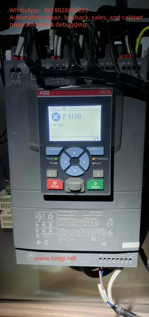
The PSTX soft starter is equipped with an intuitive human-machine interface (HMI), which enables device status monitoring, parameter setting, and fault diagnosis through the display screen and buttons. Below are the specific functions of the operation panel:
1. Display Screen
- Real-time Data Display: Displays the motor’s operating status, including parameters such as current, voltage, and power factor.
- Fault Prompt: Displays fault codes and brief descriptions for quick diagnosis.
- Menu Navigation: Displays multi-level menus, allowing users to browse setting options.
2. Button Functions
- Navigation Keys (Up, Down, Left, Right): Used to move the cursor in the menu or adjust parameter values.
- Confirm Key (Enter): Confirms selections or saves settings.
- Return Key (Esc): Exits the current menu or cancels operations.
- Reset Key (Reset): Clears fault status or restarts the device.
- Start/Stop Key (some models): Directly controls the motor’s start and stop (in local mode).
3. Operation Methods
- Enter the Main Menu: Press the “Menu” key (or long-press the navigation key, depending on the model).
- Navigate to the Desired Function: Use the up and down keys to select modules such as “Basic Settings”, “Protection Settings”, or “Diagnostic Information”.
- Modify Parameters: After selecting a parameter, press the “Enter” key to enter the editing mode. Use the navigation keys to adjust the value and press “Enter” again to save.
For detailed operation instructions of the HMI, refer to Chapter 6 “Human-Machine Interface” in the manual. It is recommended that users familiarize themselves with the button layout to improve operation efficiency.
II. Parameter Initialization
Parameter initialization is used to restore the PSTX soft starter to its factory default settings, which is applicable for debugging or resetting after a fault. The operation steps are as follows:
- Enter the HMI main menu and select “System Settings”.
- Navigate to “Reset to Factory Defaults”.
- Press the “Enter” key to confirm, and the screen will prompt “Confirm reset?”.
- Press the “Enter” key again, and the device will reset all parameters and restart.
Note: Initialization will clear all user settings. It is recommended to back up the parameters first (see “Parameter Copying” below).
III. Copying Parameters to Another Device
The PSTX supports copying parameters from one soft starter to another device, facilitating batch configuration. There are two methods:
1. Copying via HMI
- Backup Parameters:
- Enter the “System Settings” menu and select “Parameter Backup”.
- Press the “Enter” key to save the current parameters to the internal memory.
- Restore Parameters:
- On the target device, enter the “System Settings” menu and select “Parameter Restore”.
- Press the “Enter” key to load the backup parameters and restart the device after completion.
2. Copying via PSTX Configurator Software
- Export Parameters:
- Connect the soft starter to the computer using a USB or communication interface.
- Open the PSTX Configurator software and read the device parameters.
- Select “Export” and save as a parameter file (.prm format).
- Import Parameters:
- Connect the target device and open the software.
- Select “Import”, load the parameter file, and write it to the device.
IV. Password Setting and Removal
The PSTX provides a password protection function to prevent unauthorized parameter modifications.
1. Set Password
- Enter “System Settings” → “User Access”.
- Select “Set Password”.
- Enter a 4-digit password (e.g., “1234”) and press “Enter” to confirm.
- Enter the same password again for verification. The password will take effect after successful saving.
2. Remove Password
- Enter the “User Access” menu and select “Disable Password”.
- Enter the current password and press “Enter” to confirm.
- After the password is cleared, the device will return to an unprotected state.
Tip: If the password is forgotten, contact ABB technical support to reset it using administrator privileges.
V. External Terminal Start Mode
The PSTX supports controlling the motor’s start and stop through external terminals, which is suitable for PLC or manual switch control.
1. Wiring
- Start Terminal (Start): Connect to the “Start” pin of the control terminal block (usually marked as “1”).
- Stop Terminal (Stop): Connect to the “Stop” pin (usually marked as “2”).
- Common Terminal (COM): Connect to the common terminal of the control power supply.
2. Configuration
- Enter the “Control Settings” menu in the HMI.
- Set the “Control Mode” to “External Terminal”.
- Save the settings and exit.
3. Operation
- Close the switch between the “Start” terminal and “COM”, and the motor will start.
- Close the switch between the “Stop” terminal and “COM”, and the motor will stop.
VI. Bypass Control Implementation
Bypass control connects the power supply directly through a bypass contactor after the motor reaches full speed, bypassing the soft starter to reduce energy consumption.
1. Wiring
- Bypass Contactor: Connect to the bypass output terminals of the soft starter (marked as “Bypass” or “BP”).
- Main Circuit: Connect the main contacts of the bypass contactor in parallel between the input (L1, L2, L3) and output (T1, T2, T3) of the soft starter.
2. Configuration
- Enter the “Function Settings” menu in the HMI.
- Enable “Bypass Mode”.
- Set the “Bypass Delay”, usually 0.5-2 seconds, to ensure the motor is at full speed before switching.
3. Working Principle
- When starting, the soft starter controls the motor’s acceleration.
- After reaching full speed, the PSTX outputs a signal to close the bypass contactor, and the motor is directly powered by the power supply.
VII. Wiring Methods
1. Main Circuit Wiring
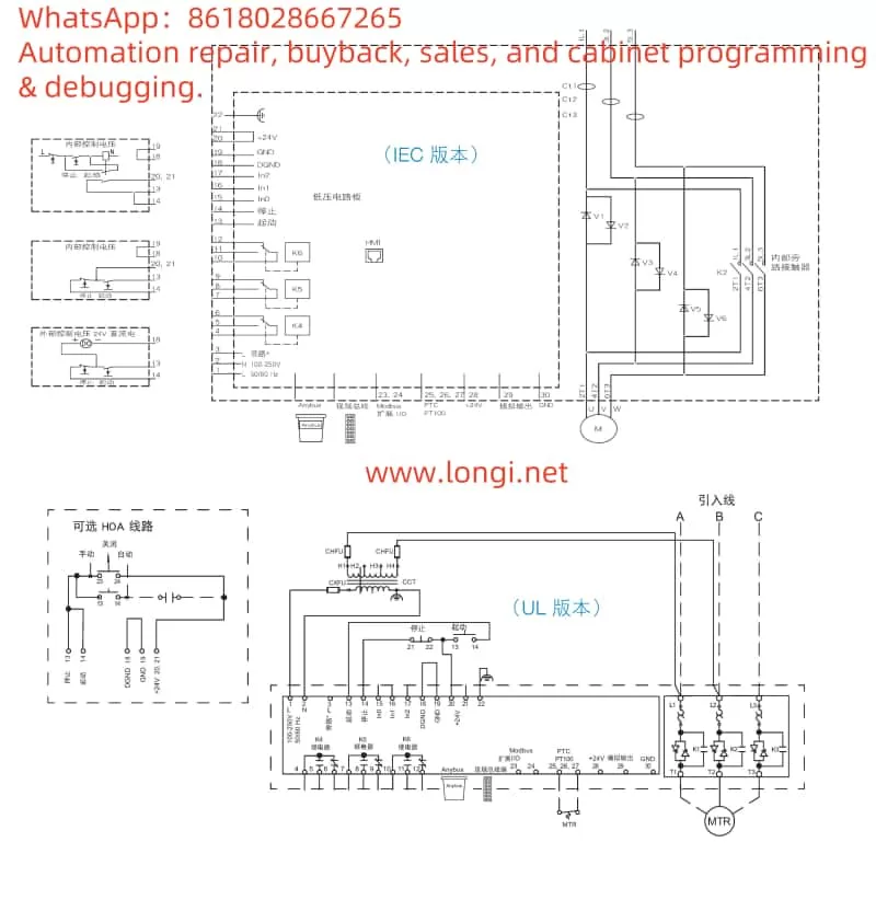
The main circuit connects the power supply and the motor. The schematic diagram is as follows (based on Chapter 4 of the manual):
复制代码Power Input Soft Starter MotorL1 ----+------[ L1 T1 ]------+---- M1L2 ----+------[ L2 T2 ]------+---- M2L3 ----+------[ L3 T3 ]------+---- M3 | | +--------[ PE ]---------+---- GND- L1, L2, L3: Three-phase power input.
- T1, T2, T3: Motor output.
- PE: Grounding terminal.
2. Control Circuit Wiring
The control circuit is used for signal input and output. The schematic diagram is as follows:
复制代码Control Power Soft Starter Control Terminals+24V ----+----[ COM ] |----[ Start ]----[ Switch ] |----[ Stop ]----[ Switch ] |----[ Fault ]----[ Alarm ]GND -----+----[ GND ]- Start/Stop: Connect to external switches or PLCs.
- Fault: Fault signal output, used for external indication.
Note: Refer to Chapter 4 of the manual for wiring photos to ensure accuracy.
VIII. Important Parameter Settings
The following are the key parameters of the PSTX and their functions:
| Parameter Name | Function | Recommended Value |
|---|---|---|
| Start Time | Controls the motor’s acceleration time | 2-20 seconds |
| Current Limit | Limits the start current multiple | 2-4 times the rated current |
| Overload Protection | Sets the overload threshold | 1.1-1.5 times the rated current |
| Stop Time | Controls the deceleration stop time | 5-30 seconds |
| Bypass Delay | Time to switch to bypass after full speed | 0.5-2 seconds |
Setting Method: Enter the “Basic Settings” menu, adjust each parameter item by item, and save.
IX. Fault Codes and Solutions
The PSTX prompts problems through fault codes. The following are common codes and their solutions:
| Fault Code | Meaning | Solution |
|---|---|---|
| F001 | Motor Overload | Check if the load exceeds the limit and adjust the overload protection parameters |
| F002 | Soft Starter Overheating | Clean the fan and improve ventilation conditions |
| F003 | Power Phase Sequence Error | Check the wiring order of L1, L2, L3 |
| F004 | Output Short Circuit | Check the motor and wiring to eliminate the short circuit point |
| F005 | Communication Fault | Check the communication cable and settings |
Troubleshooting Steps:
- Record the fault code and refer to Chapter 11 of the manual.
- Check the wiring, load, or cooling based on the prompt.
- After repair, press the “Reset” key to clear the fault.
X. Summary
Through this guide, users can fully master the operation panel functions, parameter management, control mode settings, wiring methods, key parameter configuration, and fault handling techniques of the ABB PSTX series soft starter. It is recommended to use this guide in conjunction with the manual (document number: 1SFC132081M2001) to ensure the safe and efficient operation of the device.