I. Introduction to the Operation Panel Functions and Parameter Settings
1.1 Overview of Operation Panel Functions
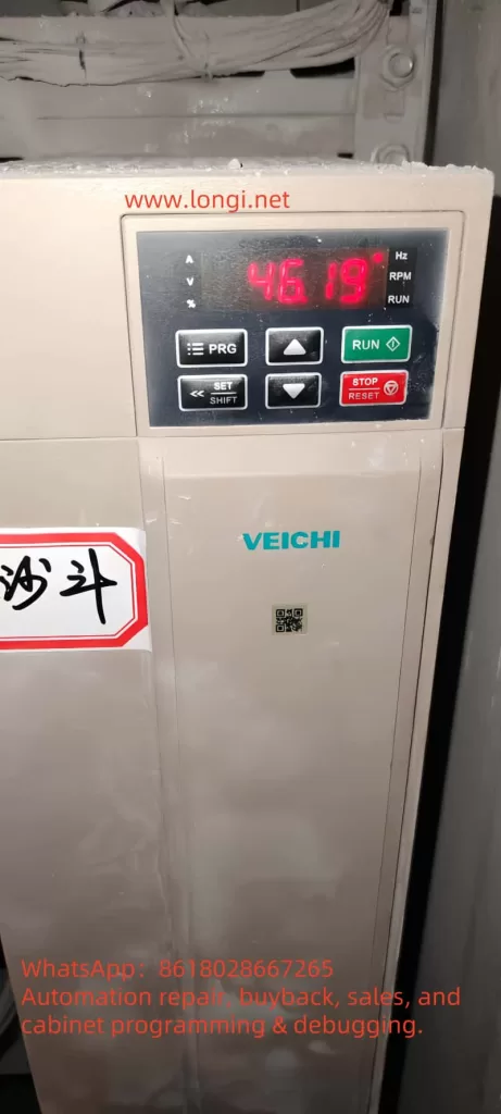
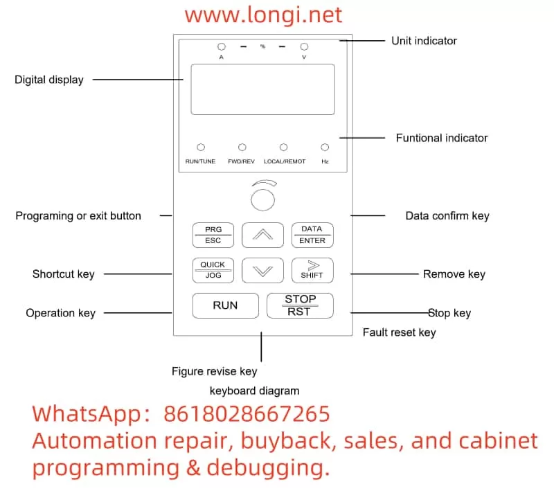
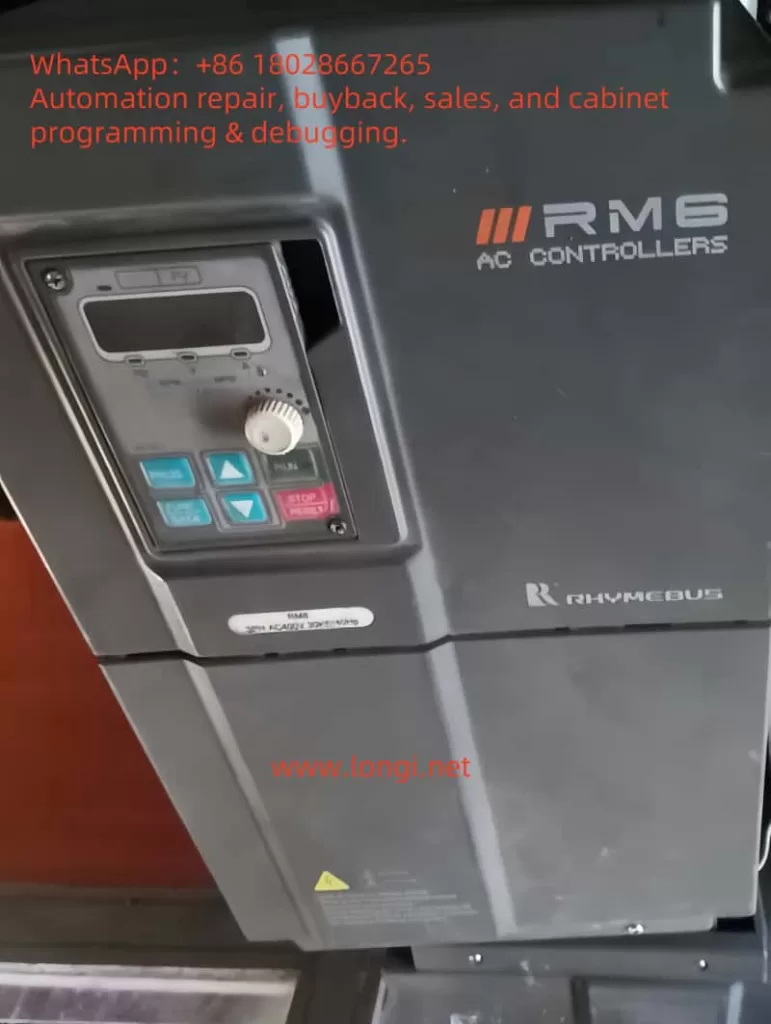
The Rhymedbus Inverter RM6 series comes equipped with an intuitive and user-friendly operation panel, which includes the following key functions:
- Power Indicator: Displays the power status of the inverter.
- Frequency Unit Indicator: Shows the current set or actual frequency unit (Hz).
- Voltage Unit Indicator: Displays the current voltage unit (V).
- Current Unit Indicator: Displays the current current unit (A).
- Program Key (PROG): Used to switch between parameter setting mode and monitoring mode.
- Function/Data Key (FUNC DATA): Enters parameter setting mode, returns to the set item, and switches monitoring screens.
- Set Knob: Adjusts frequency commands or other parameter settings.
- Run Key (RUN): Starts the inverter.
- Stop/Reset Key (STOP RESET): Stops the inverter or clears abnormal states.
- Increase/Decrease Keys: Used to change set items and parameter values.
1.2 Restoring Parameters to Factory Defaults
To restore the inverter parameters to their factory default settings, follow these steps:
- Enter Parameter Setting Mode: Press the “PROG” key to enter parameter setting mode.
- Select Factory Default Setting: Use the Increase/Decrease keys to select the F_000 (Inverter Information) parameter item.
- Choose Factory Default Restoration: Continue using the Increase/Decrease keys to select the corresponding factory default restoration option (e.g., dEF60 for 60Hz general-purpose factory defaults).
- Confirm Restoration: Press the “FUNC DATA” key to confirm restoring the factory defaults.
1.3 Password Setting and Removal
The RM6 series inverter supports parameter locking to prevent unauthorized parameter modifications.
- Setting a Password: Enter the F_213 (Parameter Lock Password Input) parameter item, use the Set Knob to enter the password value (0-9999), and press the “FUNC DATA” key to confirm.
- Removing a Password: Enter the F_214 (Parameter Lock Decoding Input) parameter item, enter the password value, and press the “FUNC DATA” key to confirm, thereby removing the password lock.
1.4 Setting Parameter Access Display
Users can set the access level and display content of parameters according to their needs:
- Parameter Access Level: Set through the F_212 (Parameter Lock Parameter Display Selection) parameter item, which can choose whether to display locked parameters.
- Monitoring Screen Selection: In monitoring mode, use the “FUNC DATA” key to switch between different monitoring screens, such as output frequency, voltage, current, etc.
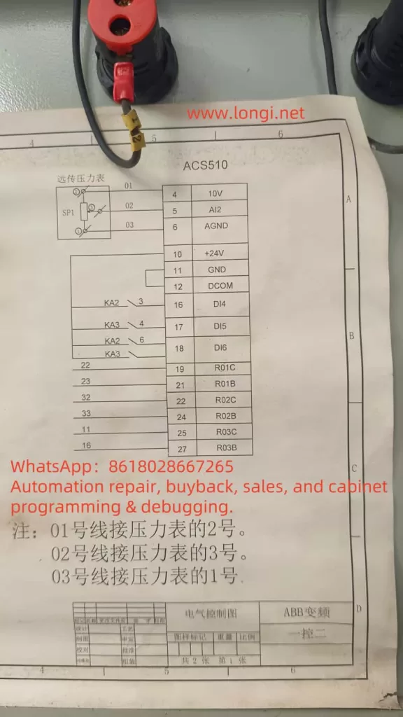
II. External Terminal Control and Speed Regulation Function Implementation
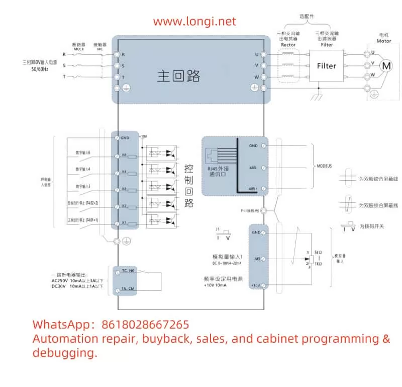
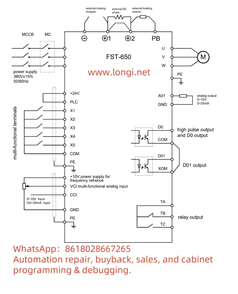
2.1 External Terminal Forward and Reverse Control
The RM6 series inverter supports forward and reverse control of the motor through external terminals, requiring the following wiring and settings:
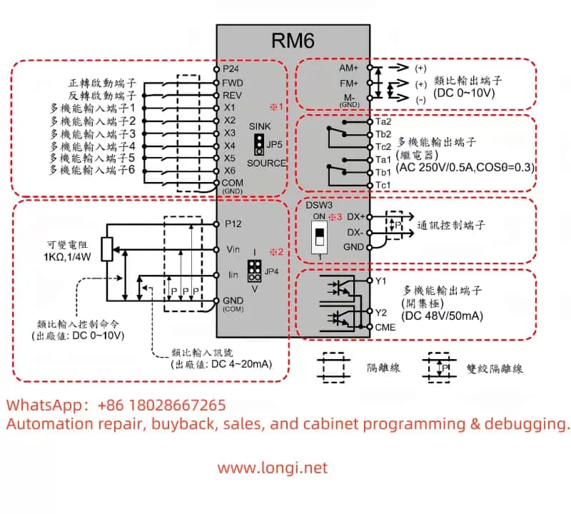
- Wiring:
- Connect the external control signals (such as buttons or relay contacts) to the inverter’s forward terminal (FWD) and reverse terminal (REV) respectively.
- Ensure the common terminal (COM) is connected correctly.
- Parameter Settings:
- Enter the F_001 (Start Control Selection) parameter item and set it to 0 or 1 (depending on the specific control mode).
- Ensure the F_003 (Operator STOP Key Priority) parameter item is set to allow external terminal control (e.g., set to 0).
2.2 External Potentiometer Speed Regulation Function
Speed regulation of the inverter can be achieved through an external potentiometer, requiring the following wiring and settings:
- Wiring:
- Connect the output terminal of the external potentiometer to the inverter’s Vin (analog input voltage) terminal.
- Ensure the potentiometer’s common terminal and the other output terminal are connected to the inverter’s GND (ground) and Vin+ terminals respectively.
- Parameter Settings:
- Enter the F_002 (Main Frequency Command Selection) parameter item and set it to 1 (controlled by analog signal).
- Enter the F_124 (Analog Input Selection (Vin)) parameter item and ensure it is set to 1 (enable Vin input).
III. Fault Codes and Troubleshooting Methods
The RM6 series inverter features comprehensive fault diagnosis functionality. When a fault occurs, the corresponding fault code will be displayed on the operation panel. Here are some common fault codes, their meanings, and troubleshooting methods:
- EEr: EEPROM error protection. Possible causes include EEPROM data write errors or EEPROM component failures. The troubleshooting method is to restore all parameter settings to factory defaults and reboot. If the error persists, send it for repair.
- AdEr: A/D converter error protection. Possible cause is A/D converter failure. The troubleshooting method is to contact customer service for repair.
- GF: Ground fault protection. Possible causes include grounding of the inverter output or poor insulation of the motor and motor wires. The troubleshooting method is to check the insulation of the motor and motor wires, and replace them if necessary.
- OE: Overvoltage protection. Possible cause is excessively high DC bus voltage inside the inverter. Troubleshooting methods include increasing the deceleration time setting, installing a dynamic brake unit, checking if the power supply voltage is within the rated input range of the inverter, etc.
- OL: Motor overload protection. Possible cause is long-term overload operation of the motor. The troubleshooting method is to check the usage of the mechanical equipment and ensure the load is within the motor’s rated range.
When a fault occurs in the inverter, first check the fault code displayed on the operation panel and follow the troubleshooting guide in the user manual for corresponding actions. If the issue cannot be resolved by the user, professional maintenance personnel or customer support should be contacted promptly.
IV. Conclusion
The Rhymedbus Inverter RM6 series user manual provides detailed operation guidelines and fault handling information, helping users better understand and utilize the inverter. By familiarizing themselves with the operation panel functions, mastering parameter setting methods, understanding the implementation of external terminal control and speed regulation functions, and being familiar with fault codes and troubleshooting methods, users can operate and maintain the inverter equipment more efficiently. In practical applications, users should flexibly configure inverter parameters and functional options according to specific needs and site conditions to achieve optimal control effects and operational efficiency.