
1. What is CPU?
CPU, also known as central processing unit, is generally composed of arithmetic unit, controller, internal memory, input/output device, interface circuit and bus. However, with the advancement and update of technology, its functions and structure are constantly expanding – the original CPU peripheral circuit is also integrated into the device. When its hardware equipment is expanded to a certain scale, so that it can independently complete a more complex control function, this device is called a microprocessor. In the microprocessor family, in order to be suitable for a certain application field, the hardware structure is different from the general microprocessor (such as 80C51) – there is a certain uniqueness. For example, the microprocessor often used in the inverter referred to in this article has a six-way PWM wave output function and can realize specific control functions. It is also called a microcontroller, alias: single-chip microcomputer. Because people in the industry generally refer to the circuit board of the inverter single-chip microcomputer as the CPU motherboard, from the perspective of convention and concise definition, this book also calls the microcontroller (single-chip microcomputer) CPU.
The microcontroller used for inverter control, also known as “high-performance microcontroller”, should be a dedicated control chip developed specifically. It should have at least six PWM wave forming and output circuits and ports to output the six inverter pulses required by the drive circuit; it should have an A/D conversion circuit, and some should also have a D/A conversion circuit to adapt to the processing of analog input and output quantities; it should have high-speed pulse signal input and output ports and serial port sending and receiving pins to process various digital signals and communication instructions; it should contain program memory and data memory to store programs, original data and rewritable data; of course, it should also have port drivers, various buffers and other circuits, which will not be repeated here.
What goes in and out of each CPU pin is nothing more than some “signal flows”. Some only go in but not out, and go but not return, such as the switch signal input by the control terminal; some only go out but not in, and go but not return, such as the relay signal output by the CPU on the control terminal; some go in and out, such as the signal transmitted between the CPU and the memory, and the operation display panel. This type of signal is bidirectional. All signals can be divided into two categories based on their nature: digital and analog. Voltage detection signals and speed control command signals are often analog, while the start and stop signals of the inverter and keyboard input signals are digital (switch quantity). Some analog signals are processed by the CPU external circuit, such as A/D conversion, before being sent to the CPU. Some directly enter the CPU pins and are processed by the internal A/D circuit. The different CPU hardware function circuits used will inevitably lead to different external circuits.
The integration of microcontrollers is high enough. It is impossible to integrate all the circuit elements required for operation without limit. It needs the active cooperation of external circuits to work. There are three working conditions that are necessary for microcontrollers, the so-called three elements of CPU operation: +5V power supply, working clock, and reset signal. The generation of working clock is generated by the oscillation circuit composed of the internal circuit of the microcontroller and the crystal oscillator element connected to the pin; the reset signal is generated by the external reset circuit when the power is on. A low-level (or high-level) pulse is sent to the reset pin of the microcontroller, and the internal circuit controls the program reset and enters the standby state. The program memory and data memory (referred to as memory) inside the microcontroller have limited capacity and use. External memory-electrically erasable memory is often required to complete some data storage tasks (especially user program storage tasks), which should constitute the four elements of the normal operation of the microcontroller. In order to accept the user’s instructions or inform the user of the working status of the inverter, the microcontroller needs a human-machine interface-operation display panel, communicate with the user, and normal communication with the operation display panel becomes the five elements of the microcontroller’s operation. In addition, the quality of the external circuits of each pin of the microcontroller will affect the operation of the microcontroller. Since then, seven or eight or even dozens of elements of the microcontroller’s operation have appeared. In fact, in my opinion, from the perspective of the microcontroller (or microprocessor, CPU) itself, three elements are necessary for the work. Without them, the microcontroller cannot meet the most basic working conditions. If the microcontroller does not work due to other reasons, it is the external circuit, not the microcontroller itself that is not working, right?
The external circuit and external framework of the microcontroller have been built, but a “body” alone cannot work. It also needs a “soul” to command the operation of the body – the software control program. The program capacity of the inverter is large, generally up to thousands of lines. The control function of the microcontroller is concentrated on two points. One is the control of the output PWM wave. In this regard, there is a clear difference between high-quality and low-quality inverters. Some PWM waves are very optimized, while others are a bit bad – the output torque is small, the operating noise is large, and the carrier interference is also large; the other is the state detection and protection of the inverter module. This task is completed in conjunction with the external circuit, and it is also the focus of the inverter circuit.
Microcontroller – single-chip computer technology has become an important technical branch of automation control technology. I hope that friends can master more relevant knowledge themselves. I will not go into details here.
The failure rate of the CPU motherboard is relatively low, accounting for about 20% of the total failure rate. Failures mostly occur in the fault detection circuit and the control terminal circuit. The inspection and maintenance of the fault detection circuit has become an important inspection content of the CPU motherboard. When the fault detection circuit (subsequent circuits for voltage and current detection, temperature detection circuit) itself is damaged, it is a bit like “falsely reporting military intelligence” and deliberately making trouble. The main circuit is obviously good, but it reports an “output short circuit” fault or an output phase failure fault. The fan is obviously good, but it reports an overheating fault, etc., which prevents the inverter from being put into normal operation. The fault of the control terminal is mostly caused by the user mistakenly connecting to a high voltage, which burns the terminal power supply 24V, the terminal input circuit is open-circuited and damaged, and the input side circuit of the photocoupler is damaged.
The damage rate of the CPU chip itself is less than 2%. Due to the technical blockade involved, the internal program is not easy to crack. General maintenance personnel do not have the relevant conditions to repair the chip. They can only purchase original manufacturer parts or replace the CPU motherboard, the so-called “board-level repair”. However, for partial damage to the CPU chip, workarounds can be used to try to repair it.
2. Principle analysis and maintenance of the basic circuit of CPU:
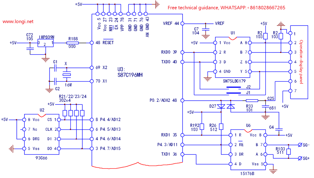
The inverter CPU motherboard circuit, which is the basic circuit for CPU operation, is composed of power supply, crystal oscillator circuit, reset circuit, external memory circuit and operation panel display circuit. The reset circuit is composed of special three-terminal reset components IMP809M and R188. It provides a low-level pulse to the 48th pin of the CPU at the moment of power-on, just like shouting the slogan “Everyone take your place”, realizing system reset and starting the program to run. The 3rd, 4th, 6th and 8th pins are connected to the U2 (93C66) memory. The user control program has been stored inside when leaving the factory. During the debugging and use process, the user needs to modify certain parameters at any time to meet the control requirements. The modified parameter values are stored by U2. The four pins connecting the CPU and the memory are all connected to +5V by pull-up resistors.
The general model of the inverter, the operation display panel, has been used as an independent device to communicate with the CPU. It accepts user instructions and transmits relevant monitoring data. The operation display panel contains CPU, decoding driver, LED display and other circuits, and can perform two-way data transmission with the CPU. Between the operation display panel and the CPU, the RS442/RS485 transceiver realizes communication transfer. The user operation signal is input from the A and B differential input terminals and sent to the CPU from the R receiver output terminal; the data signal output by the CPU enters from the D transmitter input terminal and enters the operation display panel from the Y and Z driver output terminals.
In order to adapt to the new control requirements, the control terminal of the inverter is also equipped with an RS485 communication port. In the figure, U6 (15176B) is an RS485 transceiver. D is the driver input terminal, connected to the CPU’s TXD1 serial port sending pin; R is the receiver output terminal, connected to the CPU’s RXD1 serial port receiving pin; A and B are the receiver input and driver output terminals; DE and DR are the driver and receiver enable signal terminals. The working status of the driver and receiver is controlled by the level signals of these two pins.
CPU basic circuit inspection and maintenance:
The failure rate of the CPU (single-chip microcomputer) itself is extremely low. Except for abnormal situations such as damage caused by lightning strikes introduced by the inverter, electrical failures are rare. The CPU is damaged because it contains running programs. For the sake of technical confidentiality, the manufacturer has taken some confidentiality measures to the greatest extent possible. It is difficult to decrypt the program and re-copy the chip. General maintenance personnel do not have such technical means. Does this also involve the issue of intellectual property rights? Therefore, after damage, it is necessary to purchase a chip with the program copied from the manufacturer, or replace it from a circuit board of the same model, or simply replace it with a CPU motherboard.
The inspection of the CPU basic circuit mainly includes the inspection of its three working elements and other working conditions, and fault repair.
The failure of the CPU basic circuit (three-element circuit) is typically characterized by: after power-on and when the power supply is normal, the operation panel has no display, or displays a fixed character, the inverter has no initialization process, and all operations on the operation display panel fail, similar to the phenomenon that a computer cannot be turned on and “freezes”.
The nature of the fault: A. At least one of the three elements of CPU work is missing, the CPU cannot complete the initialization operation, and the program is “stuck”; B. The CPU detects the existence of a dangerous fault signal during the self-test process and is in a fault lock state. All operations are rejected. This is a “CPU motherboard pseudo-fault” phenomenon. After checking and eliminating the cause of the fault, the CPU “strike” phenomenon will disappear immediately; C. The CPU chip is damaged due to lightning strike or abnormal power supply.
Note: If the program is “stuck”, be sure to eliminate the “CPU mainboard pseudo-fault” first, and then inspect the three elements of the CPU and other circuits. Focus on inspecting the OC fault alarm circuit, see the relevant content of Chapters 4 and 5 for details.
To determine whether the CPU is working or the three-element circuits are normal, you can first make a rough judgment:
(1).When the inverter is powered on, listen carefully to see if there is a “click” sound from the charging relay or contactor. If there is, it means that the three-element circuits are normal and the CPU is working normally. The inverter is in a fault lock state;
(2)Observe the operation display panel. Generally, there is a “power-on character” that flashes and finally stabilizes to a certain character. This process indicates that the CPU has also entered the working state.
(3)If you know the power-on self-test process of the inverter and the potential status of each pin, you can detect the voltage changes and level status of the relevant pins to determine whether the CPU is in operation. Use the key signal input of the operation display panel and the voltage changes of the key points of the detection circuit to determine whether the CPU is in working state. If you press the reset button on the panel, the inverter status signal output relay may make a “click” opening and breaking sound, and at the same time, the reset signal input pin of the drive circuit has a corresponding level change. This means that the CPU can accept the reset signal input and can output the fault reset signal to the drive circuit. This means that the CPU is working normally.
(4)If it is determined that the CPU is not operating normally, the basic working circuit of the CPU can be checked.
Fault inspection of the three-element circuit:
A、 Check the +5V power supply circuit. Check the CPU’s VDD, VSS, Vcc, GND and other power pins to confirm that the power supply is normal. The +5V power supply circuit is often connected to a filter capacitor with a large capacity of thousands of microfarads. When its capacity drops seriously, the CPU program will run disorderly and easily enter a program “dead loop”;
B、Check the reset circuit. The reset circuit provides a pulse voltage for the reset pin of the CPU during the power-on period. The duration of the pulse voltage is μs . Therefore, if a low pulse is required for reset, the static voltage of the CPU reset pin should be +5V. If a high level pulse is required for reset, the static voltage of the CPU reset pin should be 0V low level. Detection methods for the reset circuit:
a. According to the CPU reset pin’s requirement for high or low pulse voltage, measure whether its static potential is normal. If the static voltage is abnormal, check the CPU external reset circuit. You can disconnect the CPU pin to determine whether the abnormal reset pin voltage is a reset circuit failure or the CPU reset pin’s internal circuit is damaged.
b. If the static voltage is normal, you can use the artificial forced reset method to determine whether the CPU can work normally. The method is: if the static voltage of the CPU reset pin is +5V, use a metal wire to quickly short the reset pin and the power supply ground to artificially form a low-level signal input; if the static voltage of the reset pin is 0V, use a wire to quickly short the reset pin and the power supply +5V to artificially form a high-level signal input.
c. After forced reset, if the CPU can work normally, as shown by changes in the content of the operation display panel and the ability to modify parameters, it indicates that the external reset circuit is faulty and the damaged components must be replaced. For dedicated three-wire reset components, if there are no original components to replace, the RC component circuit can be connected for emergency repair;
d. If forced reset is invalid, the crystal oscillator circuit should be further checked.
3. Check the crystal oscillator circuit. The crystal oscillator circuit has few external components, usually only two capacitors and a crystal oscillator. Common circuit faults include the following:
a. Because the crystal oscillator contains quartz crystal, it is easy to break and fail after severe vibration;
b. If the crystal oscillator or capacitor leaks electricity, the signal transmission loss will increase, causing the oscillation to stop;
c. The internal oscillation circuit of the CPU is damaged and the CPU needs to be replaced.
Measurement method: a. The oscillation pulse is a rectangular square wave, and its pin voltage is about the middle value of 0V and +5V. The voltage values of the two pins are slightly different, about 0.3V. Among them, the X2 pin is 2V, and the X1 pin is 2.3V. Please use the voltage range of the digital multimeter when measuring. If you use a pointer meter, due to the low internal resistance, it may cause oscillation to stop, making the measurement result inaccurate; b. If the crystal oscillator leaks slightly or the performance deteriorates, when the crystal oscillator pin is lightly ironed with an electric soldering iron, the CPU motherboard resumes normal operation. It may be that the crystal oscillator is inefficient and the crystal oscillator should be replaced; c. If the crystal oscillator is suspected to be bad, it is best to replace it with a good crystal oscillator for testing. When removing the crystal oscillator for inspection, you can shake the crystal oscillator and carefully observe whether there is a slight clattering sound inside it. If there is, it means that the crystal oscillator is damaged by vibration. Measure the resistance value of the two pins, which should be infinite. If there is a resistance value, it means leakage. If there is a capacitance meter to measure the two pins, a good crystal oscillator has a PF-level capacitance, and its capacitance value decreases with the increase of the nominal frequency. e. There is another rare situation of defective crystal oscillator. Due to structural deformation or mechanical aging, the circuit oscillation frequency is lower than the nominal frequency value, and the frequency of CPU clock pulse is reduced. First, the system operation slows down. Second, due to the change of time reference value, the CPU sampling of input current and voltage signals will have errors, and the display values of running current and output frequency will also have corresponding deviations. In severe cases, the CPU may stop by mistake. The occurrence of this fault is manifested as a difficult fault.
Check the fault of CPU external memory. The inverter can be operated and the parameters can be modified, but after power failure, the modified parameter value cannot be stored, indicating that the machine has an external memory fault. Check the power supply of CPU external memory and the status of the connection line with CPU. Because the “pulse stream signal” is transmitted between CPU and external memory, it is difficult to judge whether it works well or not by the voltage of its pins. You can remove a good memory from the same model circuit board and replace it for testing. Note: If a new blank memory chip is used, the machine will not work. The user control parameters are already stored in the memory when it leaves the factory. If conditions permit, the original storage content can be copied to the new chip. Or purchase the memory chip from the manufacturer and replace it.
Inspection and maintenance of the operation display panel. 1. The buttons and speed regulating potentiometers on the operation display panel are wearing parts. Due to dust and humidity at the work site, they may cause poor contact, unstable output frequency or failure to write parameters. They can be replaced and repaired. 2. The LED display strokes are incomplete. Vibration causes internal drive circuit pins to be poorly soldered, copper foil strips to break, etc., which can be repaired by welding. 3. The power supply is normal, but there is no display, or a fixed character is displayed. You can replace the operation panel with the same model for testing. If the operation display panel is faulty, you can purchase a complete replacement from the manufacturer. 4. If replacing the operation display panel is invalid, check the data communication module between the CPU and the operation display panel – RS442/RS485 transceiver and other circuits.
[ Failure Example 1 ] :
A 7.5kW INVT inverter could not hear the sound of the charging relay closing when powered on, and all control operations failed. The voltage of the CPU reset control pin 48 was measured to be 2.3V, which should be 5V under normal circumstances. It was determined that the three-wire reset element IMP809M was defective. After replacement, the fault was eliminated.
[ Failure Example 2 ] :
A Fuji 5000G9S 11kW inverter had a fixed character displayed on the operation panel and could not be operated. The “program stuck” phenomenon occurred and was determined to be a CPU mainboard failure. The static voltage of the CPU reset control pin was measured after powering on and was normal. The manual forced reset method was ineffective. The fault disappeared when the crystal oscillator soldering pin was heated with a soldering iron. After replacing a high-quality crystal oscillator component and two ceramic capacitors, the fault was eliminated.
[ Failure Example 3 ] :
A Fuji 5000G9S 47kW inverter, the operation panel displays a fixed character, cannot be operated, and the “program stuck” phenomenon occurs, which is judged to be a CPU mainboard failure. After starting the machine for inspection, power on, and measuring the CPU power supply, it is normal, but the CPU chip is hot and has an abnormal temperature rise. It is judged that the CPU chip itself has a short circuit fault. A CPU chip of the same model is removed from an old circuit and replaced to eliminate the fault.
[ Failure Example 4 ] :
An INVT INVT-G9-004T4 low-power machine was found to have a damaged inverter module. The CPU mainboard and power driver board were powered on first, and the inverter module was purchased after the driver board failure was repaired. After powering on, the operation display panel showed H:00, and all the buttons on the panel failed to operate. It was determined to be a failure of the CPU basic circuit. The three working elements of the CPU were checked first, and no abnormalities were found; the other peripheral circuits of the CPU were checked, and no abnormalities were found. For a while, I was at a loss and did not know where to start, and the maintenance work came to a deadlock.
Later, when checking the current detection circuit, the voltage of the 8th and 14th pins of the current signal input amplifier U12D was 0V, which was normal; the 14th pin of U13D was negative 8V, which was an overcurrent signal output error. But logically, the CPU should report OL or OC, SC faults, and the program should not stop running, right? Try to cut off the fault signal so that it cannot be input into the CPU, power on, and the operation panel can actually be operated!
The protection sequence of INVT G9/P9 inverter is roughly as follows: when the power inverter output part is detected to be faulty at power-on, even if the start/stop signal is not received, the SC–output short circuit fault code will still be displayed, and all operations will be rejected; when the overcurrent signal from the current detection circuit is detected at power-on, H.00 will be displayed, and all operations will still be rejected at this time; when the power-on detection has a thermal alarm signal, most other operations can be performed, but the start operation is rejected, perhaps the CPU thinks that the output module is still in a high temperature rise state, and it will wait for it to return to normal temperature before allowing it to start running. For module short circuit faults and overcurrent faults, in order to ensure safe operation, all operations are simply rejected! However, this protective measure is often mistaken for the program entering an infinite loop, or a CPU peripheral circuit failure, such as abnormal reset circuits and crystal oscillator circuits.
After repairing the current detection circuit and checking that there was no abnormality in the drive circuit, the fault was eliminated after replacing the power module.