
illustrate:
From the perspective of application maintenance, it is enough to master the pin functions of some IC devices, so as to measure the voltage (level) status of some pins and judge whether the IC is in normal working condition. It is too late and unnecessary to care about what kind of circuit is inside the IC. For example, for the single-chip microcomputer circuit, it is enough to focus on detecting the voltage (level) status of the power supply, reset, crystal oscillator, control signal, and input signal terminals. For digital (including optocoupler) circuits, in general, knowing the pin functions of the device, it is possible to measure and judge the quality of the IC based on the logical relationship between the input and output terminals. As for the analog circuit, half of it is used to process switch signals in the inverter circuit, such as voltage comparators, etc., and it is as convenient to detect and judge as digital circuits. Some analog circuits that process analog signals can be measured based on the obvious changes in dynamic and static voltages, which is not too difficult.
Therefore, as long as you know two points, 1: What type of chip is the IC, digital or analog circuit? 2: The pin function, is the pin an input, output or power supply pin? Then you can implement the measurement. The commonly used IC pin function diagrams of inverters are concentrated in the appendix, so you don’t have to spend a lot of time to consult the relevant manuals.
1. CPU (microcontroller) chip and peripheral IC circuit pin function diagram:
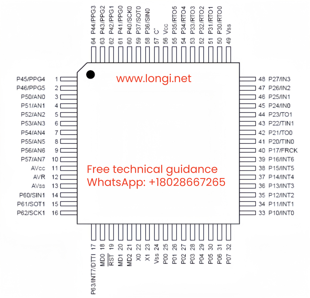
(1)CPU chip-MB90F562B SMD package 64 pins, widely used:
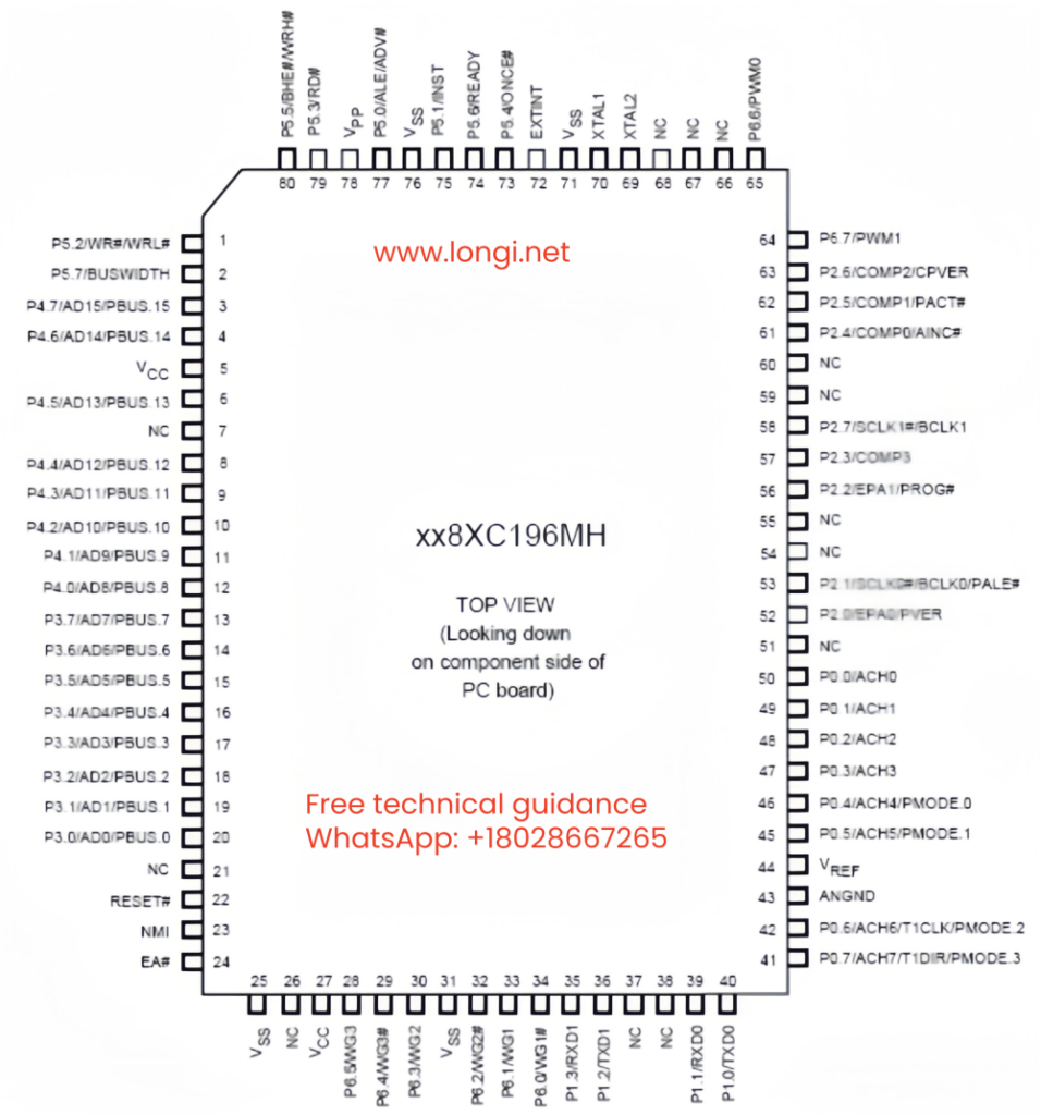
(2) CPU chip – S87C196MH SMD package 80 pins, widely used:
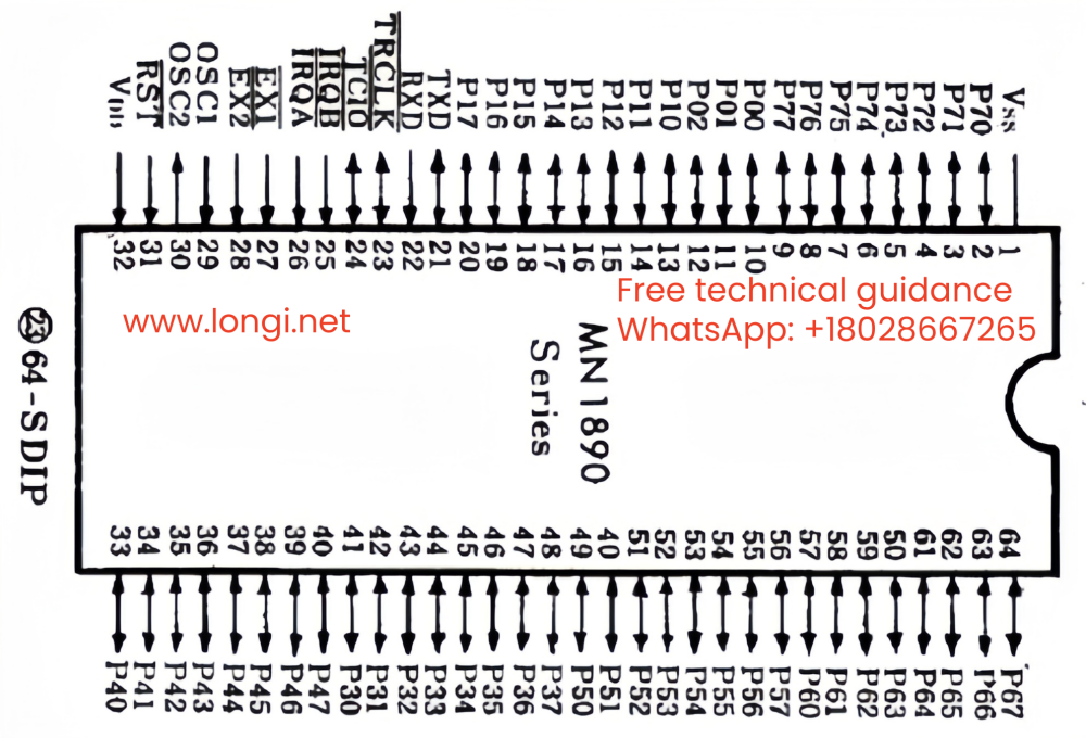
(3) CPU chip – MN18992MDY-6 plastic package dual in-line plug, 64 pins, used for Panasonic’s early DV551 and DV561 models:
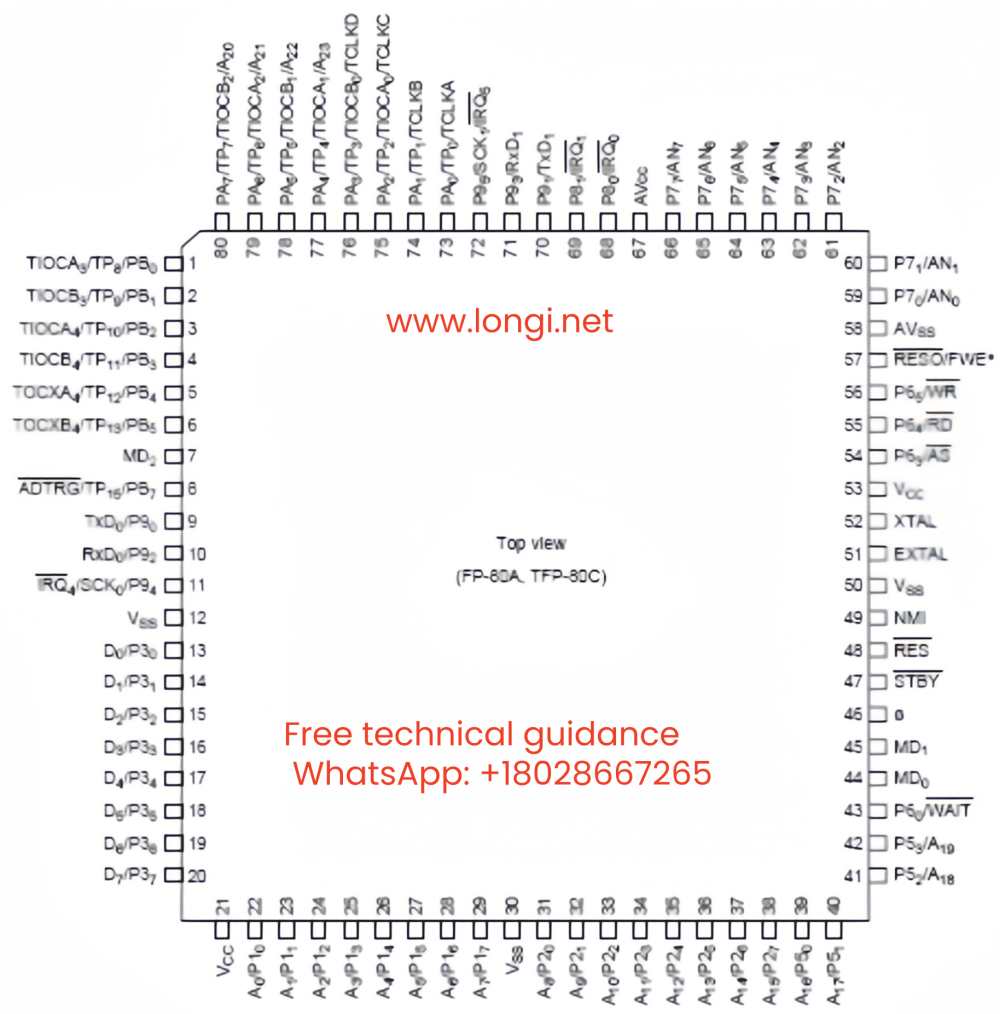
(4) CPU chip – HD6404733037F SMD package 80 pins, widely used:
(5) Memory pin function diagram:
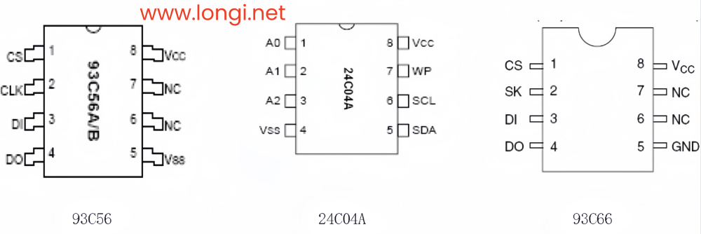
(6) RS485 communication module pin function diagram:
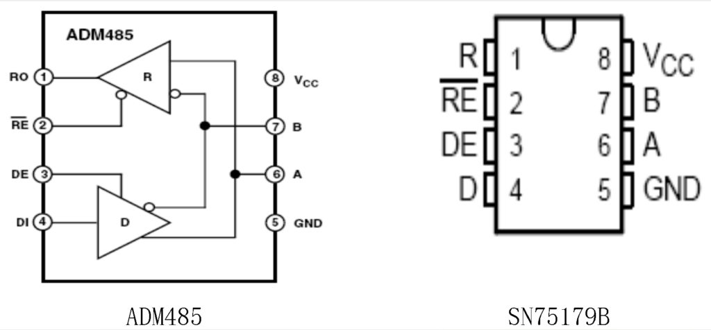
(2)Commonly used operational amplifier pin function diagram:
Operational amplifiers are mostly used in current and voltage detection circuits to process analog signals and convert them into switch signals – alarm and shutdown protection signals. Open collector output types are mostly used in voltage comparator circuits. Operational amplifiers have good interchangeability. For example, LF347, LM324, and TL072 can all be directly replaced. When the pin arrangement is inconsistent, the terminal wiring can also be replaced.
Open collector output operational amplifiers must be replaced with amplifiers of the same type.
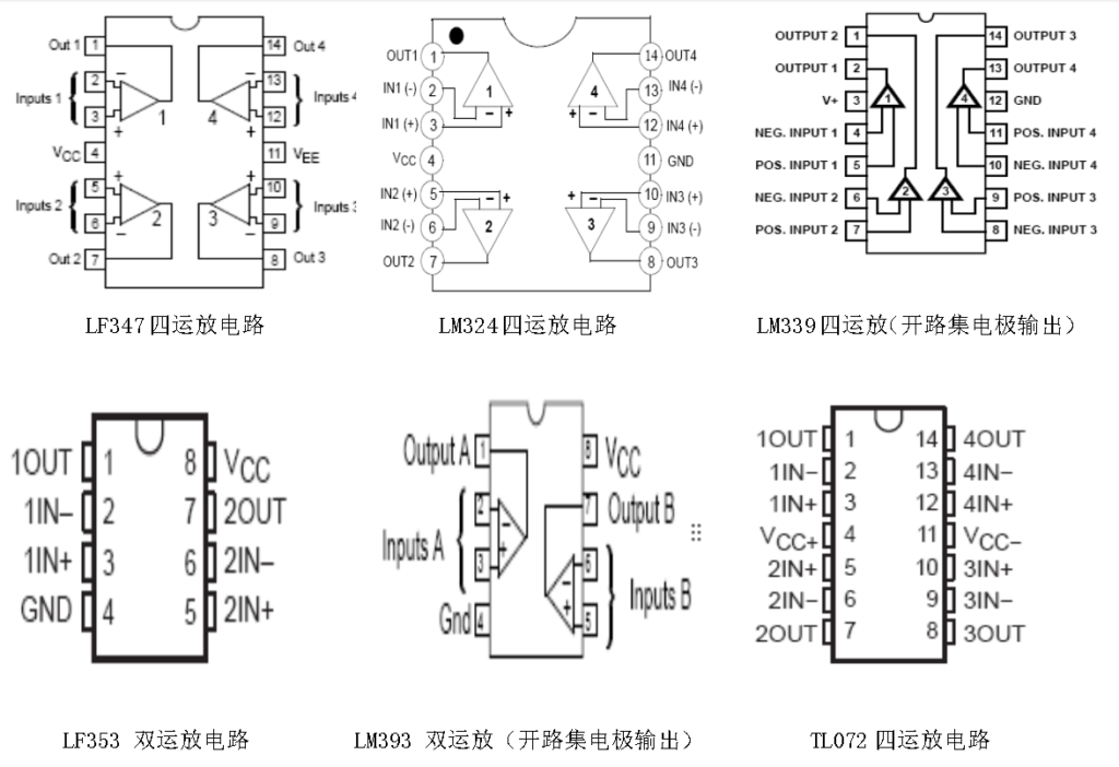
3. Commonly used digital IC circuit pin function diagram:
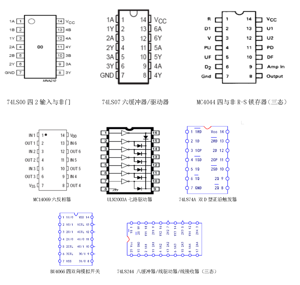
Digital integrated circuits are also divided into several types according to different materials and manufacturing processes. However, they are mainly TTL (transistor-transistor logic) integrated circuits and CMOS (complementary metal oxide semiconductor logic) integrated circuits. The 74 series TTL circuits and the 4000 series CMOS circuits are the most widely used and have the largest number of applications. TTL circuits consume slightly more power, but have higher operating frequencies and stronger output current capabilities, and the power supply voltage is 5V; CMOS circuit characteristics are the opposite. There is a wider power supply voltage range (3.0-18V ) . Under 5V power supply conditions, the same type of circuits can be interchanged. Under different power supply conditions, if the TTL circuit is damaged, you can consider replacing it with a CMOS circuit.
4. Commonly used driver ICs:
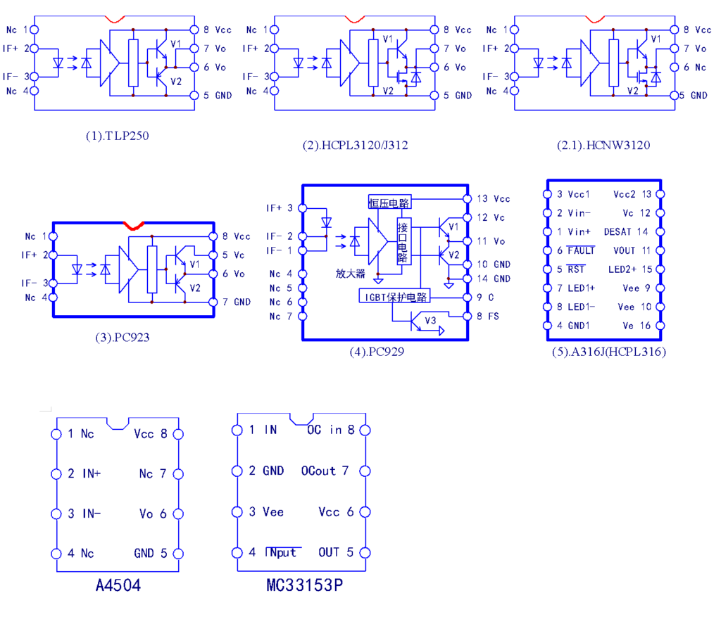
TLP250 and HCPL3120 can be directly replaced, and the output pins can be changed to replace PC923. PC923 and PC923 are often used in combination, while A4504 and MC33153 are also used in combination. The combination of the two completes the function of PC929.
5. Commonly used photocouplers:
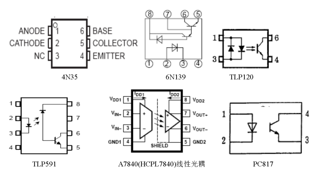
Optocouplers are used in the control terminal circuit of the inverter, voltage sampling and isolation of the switching power supply, etc. As long as it is a four-wire terminal component, it can often be replaced by PC817. Linear optocouplers cannot be replaced by ordinary optocouplers, and it is best to replace them with original model devices.
6. Switching power supply oscillation chip:
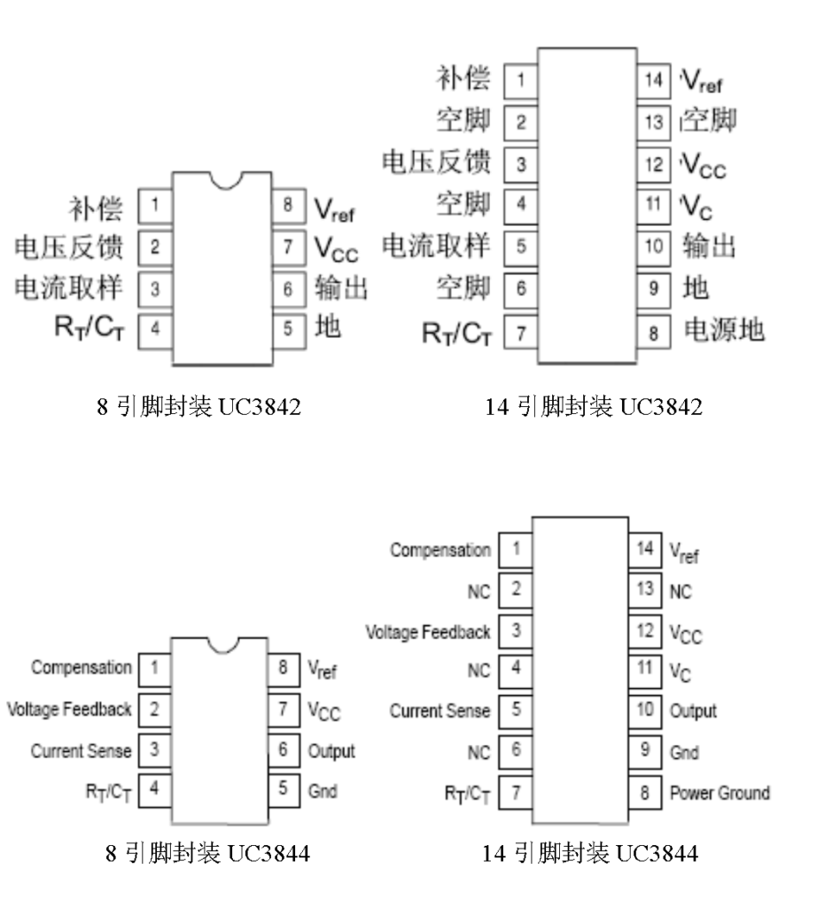
The pin functions of UC3842 and UC3844 are the same, and both have 8-pin and 14-pin packages. UC3842 and UC3843 can be interchanged; UC3844 and UC4845 can be interchanged.
7. Commonly used power (inverter) modules:
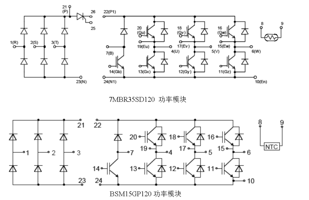
The packaging form and size of the power module are consistent, and the rated current value of the replacement module should be equal to or greater than the original damaged module.
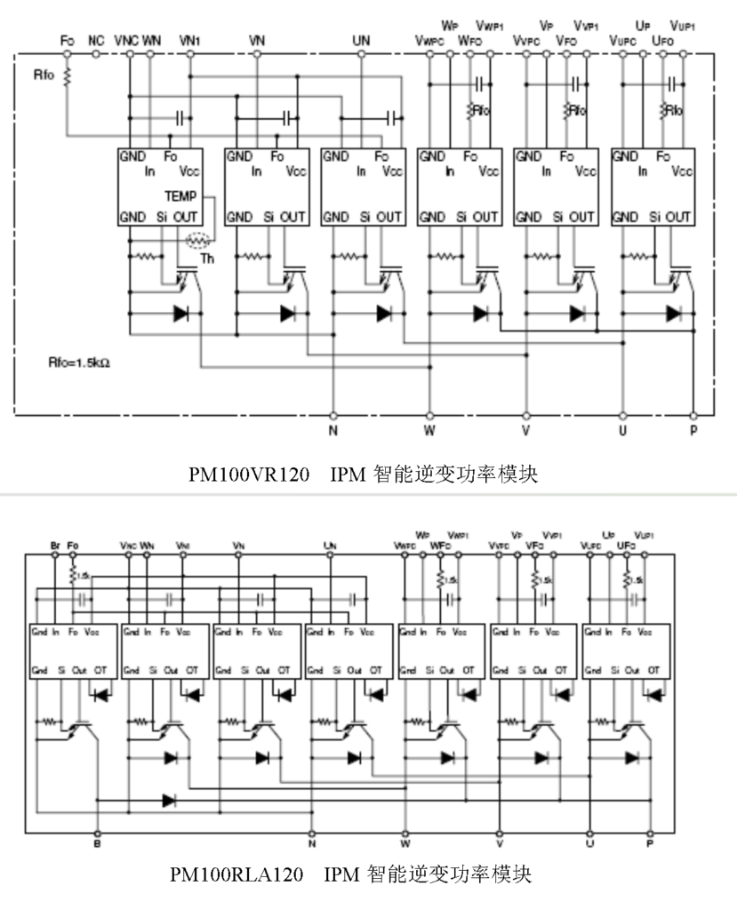
Intelligent power modules should be replaced strictly according to the original model.