
Mitsubishi E700 Inverter Operation Guide: Terminal Start, Potentiometer Speed Control, and Fault Handling
The Mitsubishi E700 series inverter is widely used in various industrial control applications due to its high performance and reliability. This guide aims to introduce the terminal start method, potentiometer frequency control, and analyze common fault codes and their solutions for this series of inverters.
I. Terminal Start Method
The terminal start function of the Mitsubishi E700 inverter allows users to control the inverter’s start and stop via external signals. Here are the basic steps to achieve terminal start:
Set the Pr.79 Operation Mode Selection Parameter:
Adjust the Pr.79 parameter to the appropriate operating mode for external control. For example, setting it to “2” puts the inverter in external operation mode, while “3” allows joint control via the operation panel and external signals.
Wiring:
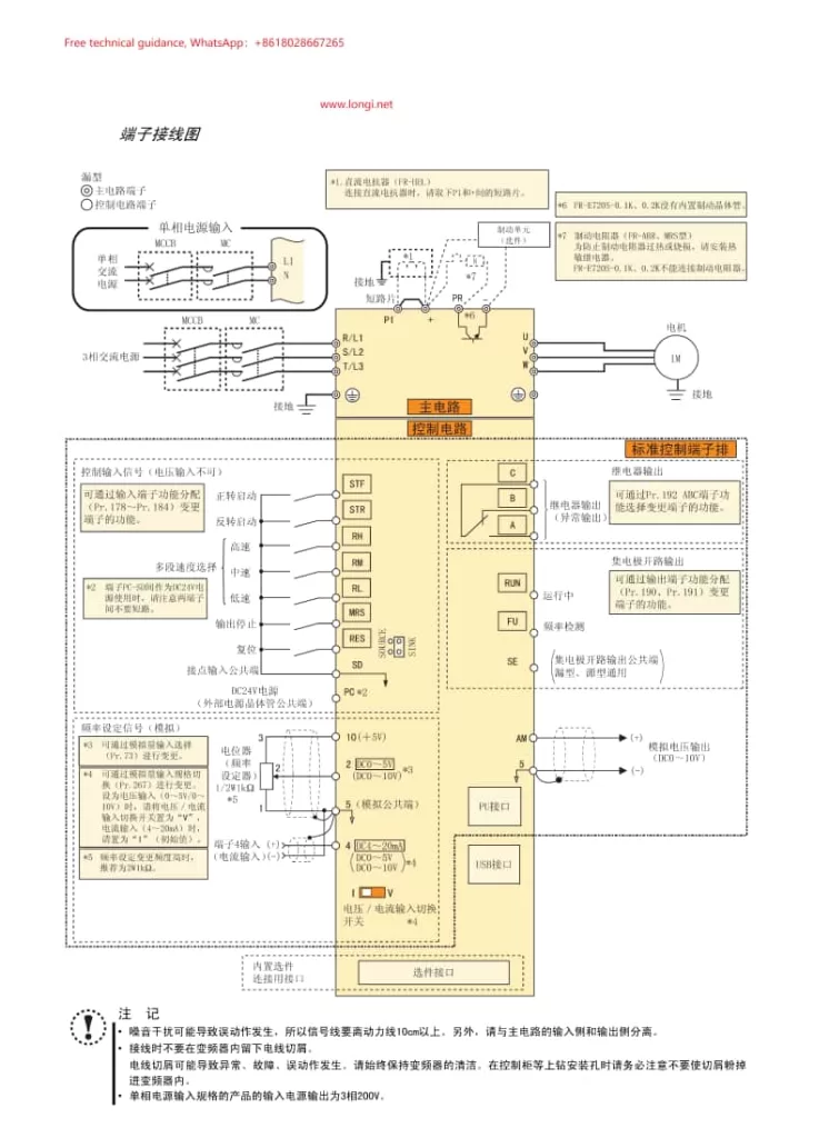
Connect the STF (forward start signal) and STR (reverse start signal) terminals to the external control device. These signals are usually dry contact signals that initiate forward or reverse rotation when they are ON.
Ensure the voltage level of the control circuit matches the inverter’s requirements.
Testing and Debugging:
After wiring and parameter settings, conduct functional tests to ensure the inverter responds correctly to external start signals.
II. Potentiometer Frequency Control
The Mitsubishi E700 inverter supports frequency adjustment via an external potentiometer, allowing for motor speed control. Here’s how to achieve it:
Parameter Settings:
Set the Pr.73 Analog Input Selection parameter to allow terminal 2 or 4 to receive analog signals (based on the inverter model and configuration).
Set Pr.161 to “1” to enable the M knob as a potentiometer mode, allowing frequency adjustment through rotating the M knob or an external potentiometer.
Wiring:
Connect the potentiometer’s output signal to the corresponding analog input terminal of the inverter (e.g., terminal 2 or 4).
Adjust the analog input gain and offset parameters (such as Pr.125 and C2) according to the potentiometer’s resistance range and output voltage/current range.
Debugging:
Rotate the potentiometer and observe the inverter’s output frequency changes to ensure the speed control function works properly.
III. Fault Codes and Solutions
During operation, the Mitsubishi E700 inverter may encounter various faults, displaying corresponding error codes. Here are some common fault codes and their solutions:
E.OC1 (Overcurrent During Acceleration):
Cause: Motor stall, too short acceleration time setting, or improper motor capacity selection.
Solution: Check the motor and load for abnormalities, extend the acceleration time, and adjust the motor capacity selection.
E.OV1 (Regenerative Overvoltage During Acceleration):
Cause: Excessive regenerative energy generated during motor deceleration, causing high DC bus voltage in the inverter.
Solution: Extend the deceleration time, enable the regenerative braking function (e.g., connect braking resistors or braking units).
E.THT (Inverter Overload):
Cause: Heavy load, high ambient temperature, or poor heat dissipation.
Solution: Reduce the load, improve heat dissipation conditions, or increase the inverter capacity.
E.OC3 (Overcurrent During Deceleration):
Cause: High load inertia during deceleration, too short deceleration time setting.
Solution: Extend the deceleration time or enable the regenerative braking function.
Er1 (Write Prohibited Error):
Cause: Attempting to modify parameters while writes are prohibited.
Solution: Check the Pr.77 Parameter Write Selection setting to ensure parameter writes are allowed.
By mastering the terminal start, potentiometer speed control functions, and fault handling methods of the Mitsubishi E700 inverter, you can effectively enhance equipment efficiency, stability, and reduce maintenance costs. We hope this guide aids you in using the Mitsubishi E700 series inverter.