AT500 Inverter Operation Guide and Fault Handling Summary
I. AT500 Inverter Operation Panel Usage
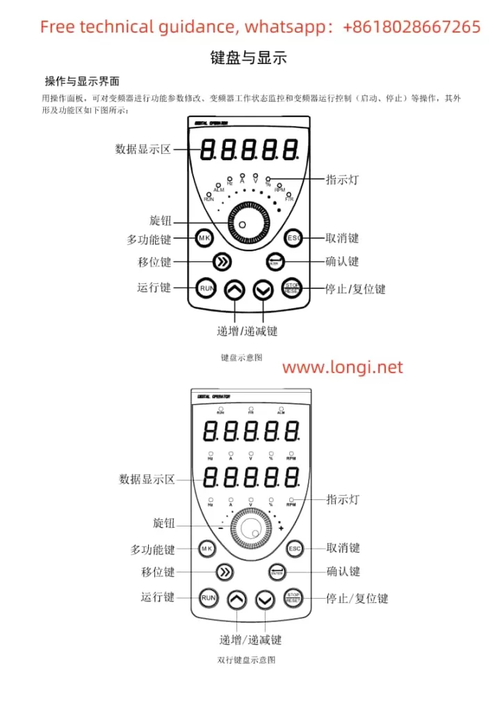
- Operation Panel Layout and Indicator Description:
- Introduces the display, buttons (RUN, STOP/RES, MK, Λ, V, >>, etc.) on the operation panel and their functions.
- Explains the meanings of various indicators (Run, Alm, Hz, A, V, %, rpm, F/R, etc.).
- Menu and Parameter Settings:
- Describes the three-level menu mode (function parameter group, function code, function code modification) and its operation method.
- Elaborates on how to view and modify various inverter parameters through the operation panel.
- Operation Mode Control:
- Introduces starting the inverter via the RUN button and stopping it via the STOP/RES button.
- Explains the jog operation function and its debugging applications.

II. Terminal Control and External Potentiometer Debugging Mode Setup
- Terminal Control Setup:
- Guides users to enter the F0 parameter group and set F0.02 to 1 to enable terminal control.
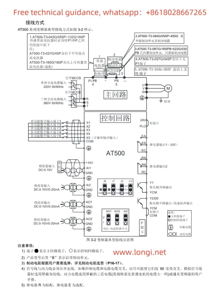
- Demonstrates how to assign functions to each input terminal through the F2 parameter group and explains wiring requirements.
- External Potentiometer Debugging Mode:
- Teaches users to set F0.03 or F0.04 to AI3 (keyboard potentiometer) to adjust the output frequency by rotating the potentiometer knob.

III. Inverter Fault Code Classification and Troubleshooting Methods
- Overcurrent Faults (Err02-Err04):
- Lists possible causes (output circuit short circuit, too short acceleration/deceleration time, etc.).
- Provides solutions (check output circuit, adjust acceleration/deceleration time, etc.).
- Overvoltage Faults (Err05-Err07):
- Analyzes fault causes (excessively high input voltage, external force during deceleration, etc.).
- Offers remedies (adjust input voltage, eliminate external force during deceleration, etc.).
- Undervoltage Fault (Err09):
- Describes fault causes (instantaneous power failure, low input voltage, etc.).
- Suggests solutions (check input power supply, adjust voltage range, etc.).
- Overload Faults (Err10-Err11):
- Indicates faults may be caused by excessive load, motor stall, etc.
- Proposes reducing the load, checking the motor and mechanical conditions, etc.
- Input/Output Phase Loss Faults (Err12-Err13):
- Analyzes fault causes (input power phase loss, faulty output wires or motor, etc.).
- Offers advice on checking power and motor, troubleshooting peripheral faults, etc.
- Module Overheating Fault (Err14):
- Explains fault causes (high ambient temperature, blocked air ducts, etc.).
- Emphasizes the importance of reducing ambient temperature, cleaning air ducts, replacing fans, etc.
- Communication Fault (Err16):
- Mentions possible causes (incorrect communication parameter settings, faulty communication cables, etc.).
- Suggests checking communication parameters, cables, and the host computer.
