
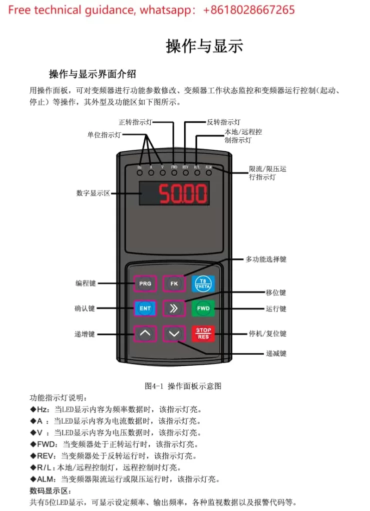
I. Procedure for Viewing and Modifying Function Codes on the T8 Series VFD Operator Panel
- Starting the Operator Panel:
- After powering on the VFD, press the power button (labeled “POWER” or similar symbol) on the operator panel to activate it.
- Viewing and Modifying Function Codes:
- Use the directional keys (↑↓←→) on the operator panel to select the desired function code for viewing or modification.
- Press the “ENTER” key to enter edit mode, where you can input new parameter values using the numeric keys or view the current values.
- After making changes, press “ENTER” again to confirm the modifications and exit edit mode.
- Note: Access to some advanced function codes may require entering a password.
- Parameter Structure and Status Parameter Review and Setting:
- VFD parameters are typically grouped, such as motor parameters (P0 group), control parameters (P1 group), and protection parameters (P2 group).
- To review specific parameters, refer to the parameter table in the manual to find the corresponding parameter number (e.g., P0.01, P1.05) and parameter description.
- Status parameters (e.g., current frequency, current, voltage) can be directly viewed through specific function codes, providing real-time insights into the VFD’s operating status.
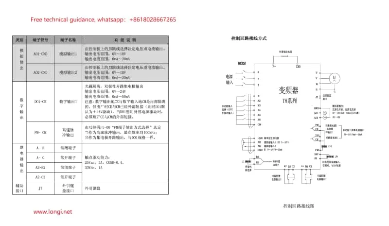
II. Explanation of Control Circuit Terminals and Wiring Methods for the T8 VFD
- Explanation of Control Circuit Terminals:
- FWD/REV (Forward/Reverse Control Terminals): Connect to external buttons or switches to control the VFD’s forward and reverse rotation.
- RUN/STOP (Run/Stop Control Terminals): Control the VFD’s start and stop functions.
- AI1/AI2 (Analog Input Terminals): Receive analog signals from potentiometers, PLCs, etc., for frequency adjustment.
- FAULT (Fault Output Terminal): Outputs a signal to external devices when the VFD detects a fault.
- RUN (Run Indicator Light): Illuminates when the VFD is in the running state.
- Wiring Methods for the Control Circuit:
- Connect the corresponding control signal wires to the designated terminals based on actual control requirements.
- When using terminal start and potentiometer adjustment, ensure:
- Analog input parameters are set correctly, including input type (voltage/current) and range.
- The frequency setting method is selected as “Analog Input.”
- Forward/reverse control parameters are set according to actual needs.
III. Explanation and Resolution of VFD Fault Codes
Based on the specific instructions in the “Theta VFD T8 Series Manual,” here are some common fault codes and their resolutions:
- OC (Overcurrent Fault): Check if the motor and load are excessively large, optimize motor parameters or load distribution; inspect motor insulation for integrity.
- OV (Overvoltage Fault): Verify input voltage stability, use a voltage stabilizer if necessary; inspect power lines for abnormalities.
- UV (Undervoltage Fault): Check the input power source for normalcy, troubleshoot power supply issues; inspect power lines for poor contact.
- OH (Overheat Fault): Improve ventilation conditions, reduce ambient temperature; check for blocked heat sinks and clean dust inside the VFD.
- EF (External Fault): Verify the normalcy of the external fault signal source; inspect the wiring of external devices for secure connections.
Please note that this content is a summary of the user guide based on select sections of the “Theta VFD T8 Series Manual.” Always refer to the original manual for detailed steps, precautions, and any additional information. For questions or further assistance, consult the manual or contact longi VFD’s technical support department.