
I. Introduction to ACS850 Inverter Features
The ABB ACS850 series inverter is a high-performance, multi-functional drive device designed specifically for industrial applications, supporting various motor types. Its key features include:
- Extensive Power Range: Covering from 0.37 kW to 560 kW, catering to the needs of small to large-scale industrial applications.
- High-Precision Control: Utilizing advanced control algorithms to provide precise motor control, including Direct Torque Control (DTC).
- Modular Design: Easy to configure and expand, supporting multiple communication protocols and fieldbus interfaces.
- Comprehensive Protection: Built-in multiple protection mechanisms to ensure stable system operation, including overcurrent, overload, and short-circuit protection.
- User-Friendly Interface: Equipped with an intuitive control panel for easy operation and monitoring.
II. Operating Instructions for ACS850 Inverter Control Panel
The control panel of the ACS850 inverter typically includes an LCD display, multiple function keys, and directional keys. While the specific key names may vary depending on the model or version of the control panel, the basic operation logic remains similar. The following are general instructions:
- Menu Navigation: Use directional keys to move up, down, left, or right in the menu to select the desired function or parameter.
- Parameter Setting: Enter the parameter setting menu, use directional keys to select specific parameters, and then adjust them using data increase/decrease keys.
- Operation Control: The panel usually has clear control keys for start, stop, forward, reverse, etc., for direct control of the inverter’s operating status.
- Display Switching: Some control panels may be equipped with dedicated keys to switch between different display modes or view alarm information.
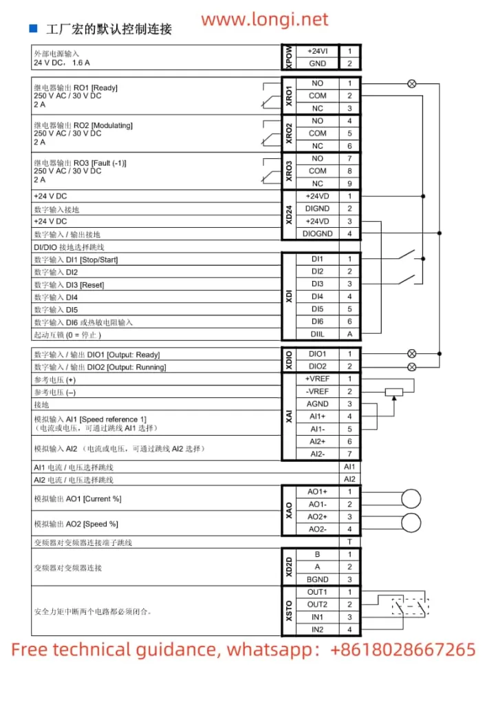
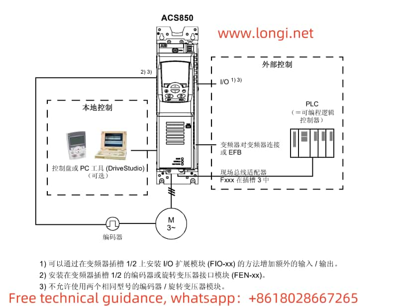
III. Configuration Guide for Terminal Control Mode
When using terminal control mode, it is necessary to select the appropriate macro configuration and set relevant parameters based on application requirements. The following are general steps:
- Select Macro Configuration: Based on the application type (e.g., fan/pump, compressor, etc.), select the suitable macro configuration in the inverter’s parameter settings. This typically involves presetting a series of related parameters to suit specific application needs.
- Configure Input/Output Terminals:
- Connect external control signals (e.g., start, stop, speed setting, etc.) to the corresponding input terminals.
- Configure output terminals as needed (e.g., fault output, operating status output, etc.).
- Set Control Parameters:
- Adjust relevant control parameters according to the selected macro configuration, such as acceleration time, deceleration time, PID controller parameters, etc.
- Ensure that AI1 (or other analog input terminals) is correctly configured as the speed setting input, and set appropriate scaling factors and offsets.
- Save Settings and Test:
- After saving all settings, test the inverter to ensure that all control signals are working as expected.
- Check and eliminate any potential wiring errors or incorrect parameter configurations.
IV. Fault Code Analysis and Troubleshooting
The ACS850 inverter features a fault diagnosis function that displays corresponding fault codes when a fault occurs. Based on the fault code table (usually located in a specific chapter of the manual), users can quickly identify the problem and take appropriate measures. The following are some common fault codes and their troubleshooting suggestions:
- 0001: Overcurrent fault. Check the motor, cables, and inverter output for normality; adjust the load or increase overload protection settings.
- 0002: DC link overvoltage fault. Check the stability of the power supply voltage; consider increasing deceleration time or installing a braking resistor.
- 0004: Motor short-circuit fault. Check the motor windings for short-circuits; replace the motor if necessary.
Note: The above steps and suggestions are based on a general description of the ACS850 series inverter. When performing specific operations, please refer to the ACS850 firmware manual and follow the official guidance provided by ABB. For any questions or issues, it is recommended to contact Longi Electromechanical Support for professional assistance.