
I. Operation Panel Functions and Instructions
The operation panel of the Great Inverter VC8000 series serves as the primary interface for user interaction with the inverter. It mainly consists of a display area and functional keys. Below are the main functions of the operation panel:
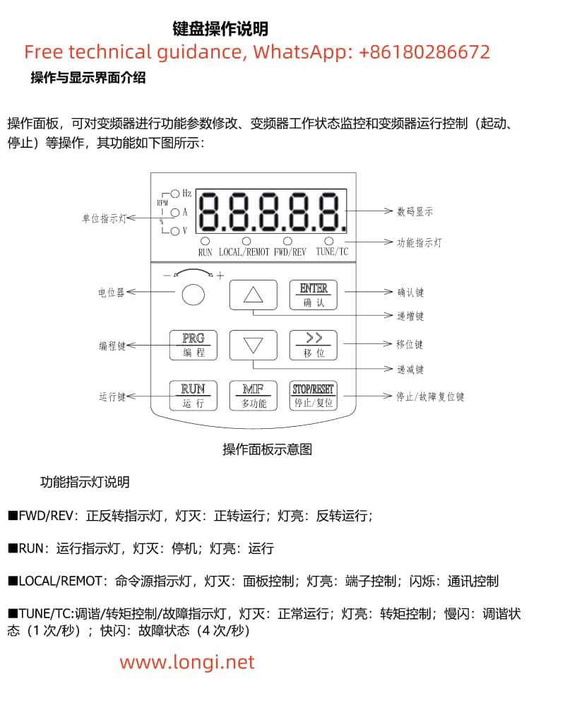
- Display Area
- Digital Display: Shows the current working status, frequency setting value, operating parameters, and other information of the inverter.
- Function Indicators:
- FWD/REV: Forward/Reverse indicator. Light off indicates forward operation, light on indicates reverse operation.
- RUN: Running indicator. Light off indicates stop, light on indicates running.
- LOCAL/REMOT: Command source indicator. Light off indicates panel control, light on indicates terminal control, flashing indicates communication control.
- TUNE/TC: Tuning/Torque Control/Fault indicator. Light off indicates normal operation, light on indicates torque control, slow flashing indicates tuning status, fast flashing indicates fault status.
- Functional Keys
- PRG/Programming: Enters or exits the menu for parameter modification.
- ENTER/Confirm: Enters the menu, confirms parameter settings.
- ▲ Increment: Increments data or function codes.
- ▼ Decrement: Decrements data or function codes.
- < Shift: Selects parameter modification digits and display content.
- RUN/Run: Starts the inverter.
- STOP/RESET: Stops or resets the inverter.
- MF/Multi-Function: Multi-function selection key, with specific functions determined by the P7-01 function code.
II. Wiring Instructions for Terminal Start/Stop and Potentiometer Debugging
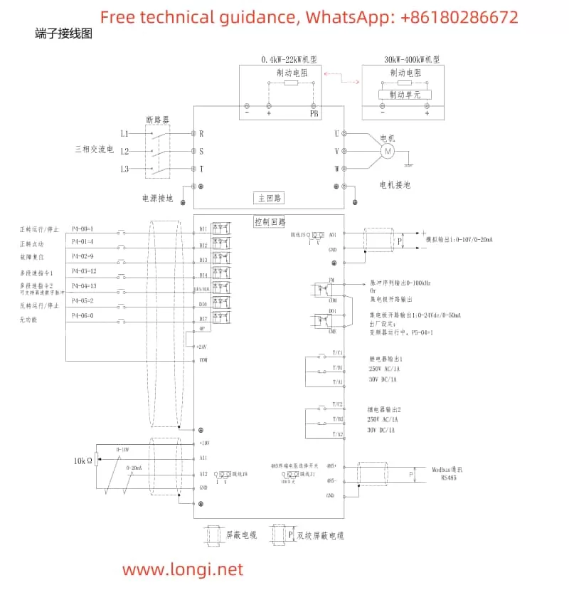

- Wiring Instructions
- Start/Stop Control Wiring:
- Start Terminal: Typically, the start signal is connected to DI1 (or another specified digital input terminal) and configured as a forward running command (e.g., P4-00=1).
- Stop Terminal: Connected to DI2 (or another specified digital input terminal) and configured as a fault reset or stop command (e.g., P4-01=9).
- Potentiometer Debugging Wiring:
- If an external potentiometer is used for frequency adjustment, connect +10V and GND to the power terminals of the potentiometer, and connect the center tap to AI1 (analog input 1).
- Start/Stop Control Wiring:
- Parameter Settings
- To meet control requirements, set the following parameters:
- P4-00: Set DI1 as the forward running command (e.g., set to 1).
- P4-01: Set DI2 function according to needs, typically as fault reset or stop command.
- AI1-related Parameters: Ensure AI1 is configured to receive frequency settings (e.g., set P0-03 to AI1).
- Other Necessary Parameters: Set relevant parameters in P0 group (basic function parameters), P2 group (vector control parameters), etc., according to specific needs.
- To meet control requirements, set the following parameters:
III. Fault Code Analysis and Solutions
When faults occur in the Gelite Inverter VC8000 series, fault codes prefixed with “ERR” will be displayed. Below are analyses and solutions for some common fault codes:
- ERR01 – Inverter Unit Protection
- Cause: May be due to inverter overheating, short circuit, or drive board failure.
- Solution: Check if the inverter module is overheating, check for short circuits in the motor and cables, and if the problem persists, contact the manufacturer for repair.
- ERR02/ERR03/ERR04 – Acceleration/Deceleration/Constant Speed Overcurrent
- Cause: Excessive motor load, short acceleration time setting, output short circuit, etc.
- Solution: Check the motor load, appropriately extend the acceleration time, and check for short circuits in the output circuit.
- ERR05 – Constant Speed Overvoltage
- Cause: Excessive power supply voltage, abnormal braking unit, etc.
- Solution: Check the power supply voltage and confirm if the braking unit is working normally.
- ERR08 – Control Power Fault
- Cause: Abnormal control power, such as unstable voltage or power cut.
- Solution: Check the control power supply voltage and ensure stable power supply.
- ERR19 – Overload
- Cause: Motor operating under overload for an extended period.
- Solution: Reduce the motor load and check for abnormalities in the mechanical parts.
Note: The above are only analyses and solutions for some fault codes. During actual use, please refer to the specific fault code manual for operation. For faults that cannot be resolved, please promptly contact longi technical support.