
I. Introduction
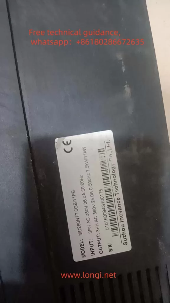
The Inovance MD280 series inverter is a powerful and user-friendly universal inverter widely applied in various automation equipment such as textile, papermaking, and machine tools. This guide will detail the operation panel functions, terminal start/stop configuration, external potentiometer speed regulation settings, and fault code troubleshooting for the MD280 inverter.
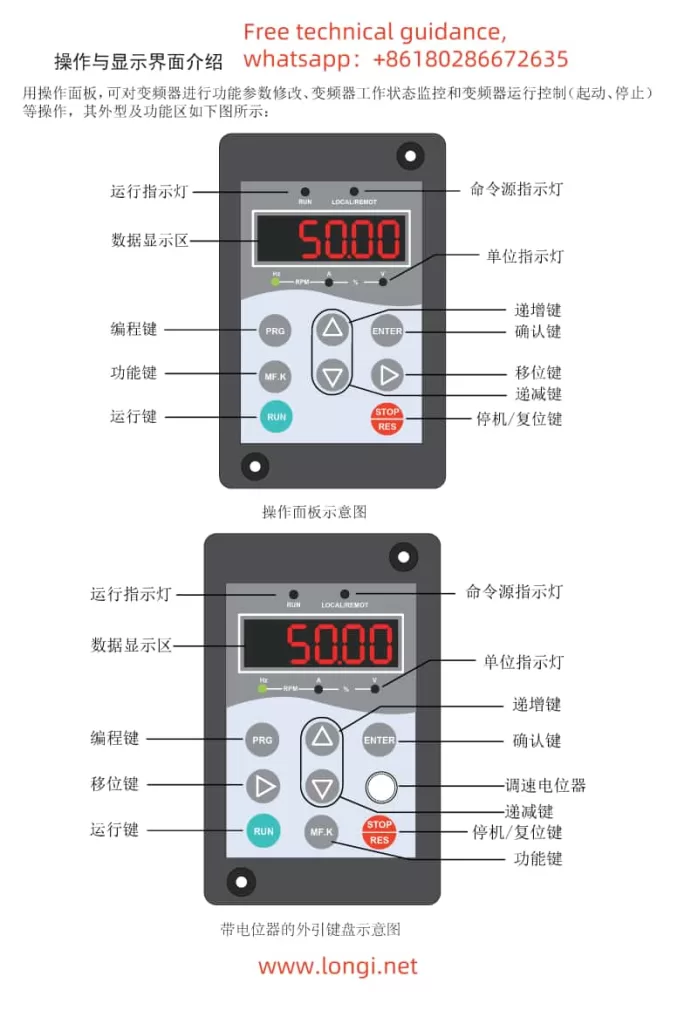
II. Operation Panel Functions and Usage
The MD280 inverter’s operation panel serves as the primary interface between the user and the inverter, providing functionality such as run, stop, reset, and speed adjustment.
- RUN Key: Pressing this key starts the inverter.
- STOP/RES Key: Used to stop the inverter or reset it in case of a fault.
- Multi-Function Key (MF.K): Depending on the setting, this key can switch command sources, toggle between forward and reverse rotation, or initiate jogging.
- Speed Adjustment Potentiometer (if equipped): Rotating the potentiometer directly adjusts the inverter’s output frequency for speed regulation.
The LED display on the panel shows the inverter’s operating status, frequency, current, and other parameters, facilitating real-time monitoring.
III. Terminal Start/Stop and External Potentiometer Speed Regulation
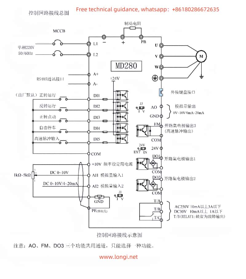
The MD280 inverter supports start/stop control through external terminals and speed regulation using an external potentiometer. Here are the detailed setup and wiring instructions:
1. Terminal Start/Stop Configuration
First, set the control command source through the inverter parameters. Navigate to the inverter parameter settings and set F0-00 to “1” (terminal command channel). Then, configure the DI terminal functions using the F2 group parameters, for example:
- Set F2-00 to “1” to assign DI1 as the forward run terminal.
- Set F2-01 to “2” to assign DI2 as the reverse run terminal.
- Set F2-04 to “8” to assign DI4 as the free stop terminal.
When wiring, connect the external start, stop buttons, or contactors to the DI1, DI2, and DI4 terminals (depending on specific requirements), ensuring the common terminals are connected to the inverter’s COM terminal.
2. External Potentiometer Speed Regulation
The MD280 inverter supports analog speed regulation via the AI2 terminal using an external potentiometer. First, set the J2 jumper on the control board to “V” (voltage input mode). Then, connect the three pins of the external potentiometer to AI2, GND, and +10V (or an equivalent voltage source from an external power supply).
In the parameter settings, ensure F0-01 is set to “1” (AI1 analog input) or “2” (AI2 analog input), depending on which AI terminal the potentiometer is connected to. Additionally, configure the AI input minimum and maximum values, along with the corresponding output frequency range, using parameters F2-09 to F2-12.
IV. Fault Code Meanings and Solutions
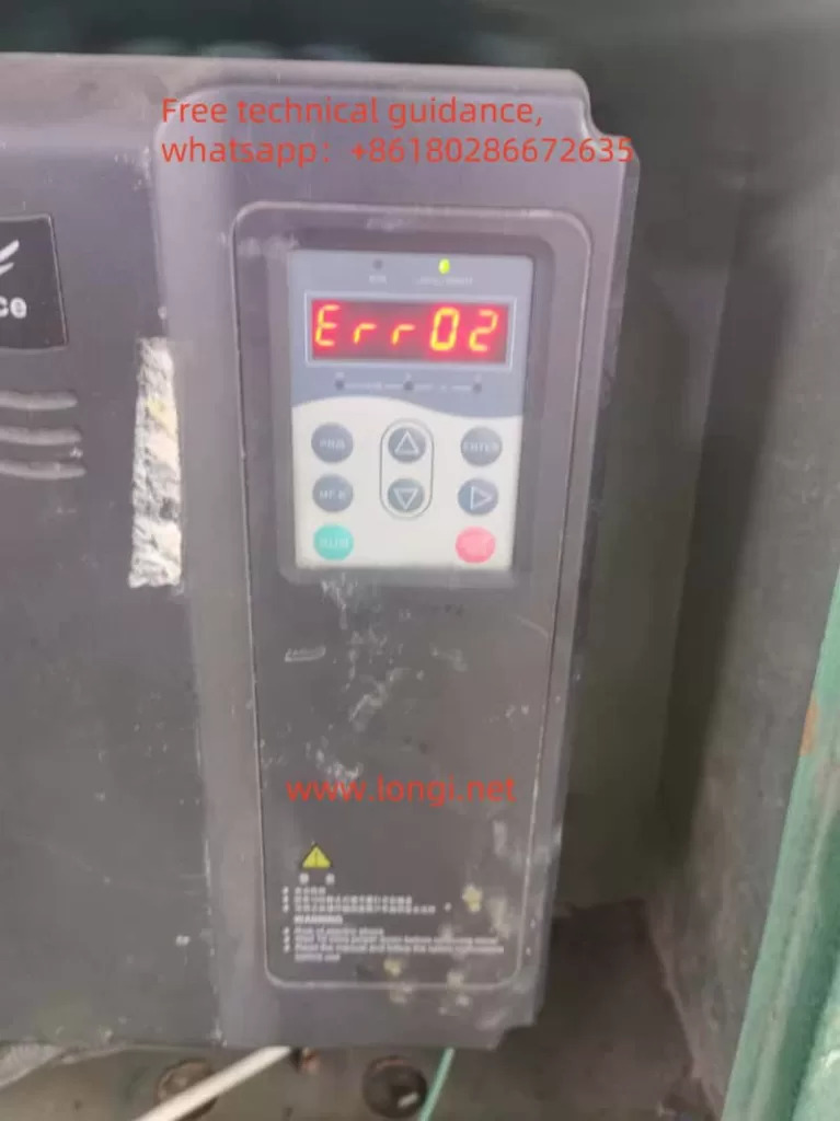
During operation, the MD280 inverter may encounter various faults and display corresponding fault codes on the LED screen. Here’s an explanation and solution for ERR02:
ERR02: Acceleration Overcurrent
- Meaning: The inverter detects an overcurrent during acceleration.
- Possible Causes:
- Excessive motor load.
- Too short acceleration time setting.
- Improper V/F curve configuration.
- Solutions:
- Check if the motor load exceeds the rated capacity and reduce the load if necessary.
- Increase the acceleration time (adjust parameter F0-09).
- Optimize the V/F curve settings by adjusting parameters like F1-05 (torque boost).
- Inspect the motor and connecting cables for short circuits or ground faults.
By following these steps, you can effectively resolve the ERR02 fault encountered during MD280 inverter operation, ensuring stable equipment performance.
V. Conclusion
The Inovance MD280 series inverter, with its robust functionality and user-friendly operation, holds a significant position in various automation equipment. This guide aims to enhance your understanding of the inverter’s operation panel functions, terminal start/stop and external potentiometer speed regulation settings, as well as fault code troubleshooting. By mastering these concepts, you can fully leverage the inverter’s performance advantages, boosting production efficiency.