
I. Introduction to the Operation Panel Functions
The Haishida HSD260 series VFD’s operation panel offers a variety of functions, enabling users to conveniently set, monitor, and control the VFD’s operation. The following are the main function introductions of the operation panel:

- Display Settings
To set the display to show actual current instead of frequency, you need to access the parameter setting interface via the PRG key and adjust the relevant function codes. The specific steps are as follows:
Enter parameter settings: Press the PRG key to enter the P-group function parameter setting interface.
Select display parameter: Use the ▲ (increment) and ▼ (decrement) keys to find and select the parameter you want to display, such as U0-04 (output current).
Confirm and exit: Press the ENTER key to confirm your selection and exit the parameter setting interface via the PRG key. The operation panel will now display the value of the selected parameter.
- Start/Stop Operations
Start: Press the RUN key to start the VFD. If the command source (P0-02) is set to the operation panel, pressing the RUN key will start the VFD.
Stop: Press the RUN key again to stop the VFD. If the VFD is in a fault state, pressing the RUN key can also reset the fault.
- Parameter Adjustment
Enter parameter settings: Press the PRG key and use the ▲ (increment) and ▼ (decrement) keys to select the function code you need to adjust.
Modify parameter values: Press the SHIFT key to select the digit you want to modify, then use the ▲ (increment) and ▼ (decrement) keys to adjust the parameter value.
Save and exit: After making changes, press the ENTER key to save the settings and exit the parameter setting interface via the PRG key.
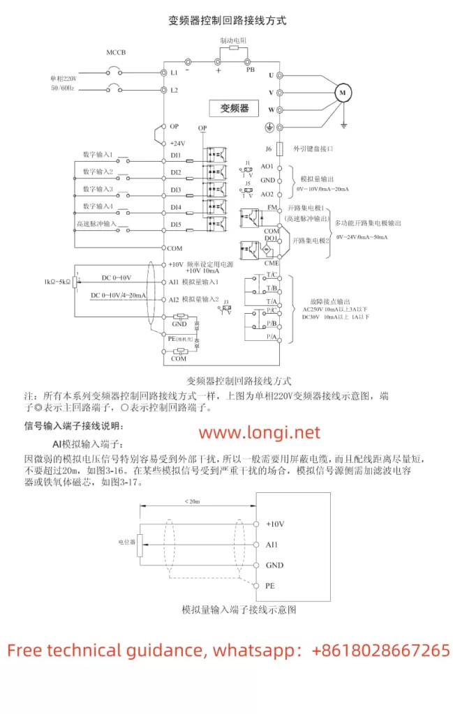
II. Terminal Start and Potentiometer Speed Control Wiring and Control Terminals
- Terminal Start
To achieve terminal start, you need to correctly wire the control terminals and set the corresponding function codes. Below is a simple example of three-wire start wiring:
Wiring Example:
DI1 (Forward Start): Connect to the start button (normally open)
COM: Common terminal
DI2 (Stop): Connect to the stop button (normally closed)
Parameter Settings:
P0-02: Command source selection, set to 1 (terminal command channel)
P4-00: DI1 terminal function selection, set to 1 (forward operation)
P4-01: DI2 terminal function selection, set to 9 (fault reset)
P4-11: Terminal command mode, set to 2 (three-wire mode)
- Potentiometer Speed Control
When using a potentiometer for speed control, you need to correctly wire the potentiometer to the VFD’s analog input terminals and set the corresponding function codes. Below is an example of potentiometer speed control wiring:
Wiring Example:
+10V: Connect to the variable resistor terminal of the potentiometer
AI1: Connect to the other end of the potentiometer
GND: Connect to the common terminal of the potentiometer
Parameter Settings:
P0-03: Main frequency source selection, set to 2 (AI1)
Ensure the potentiometer’s resistance range matches the VFD’s input requirements
III. VFD Fault Analysis and Solutions
- ERR01: Inverter Unit Protection
Fault Analysis: This fault is usually caused by short circuits in the VFD’s output circuit, excessively long motor and VFD wiring, or overheated modules.
Solution:
Check and eliminate peripheral faults.
Install reactors or output filters.
Check for blocked air ducts and ensure the fan is working properly.
Ensure all connections are properly inserted.
If the problem persists, seek technical support.
- ERR02: Acceleration Overcurrent
Fault Analysis: This fault may be caused by grounding or short circuits in the VFD’s output circuit, vector control without motor parameter tuning, or too short an acceleration time.
Solution:
Eliminate peripheral faults.
Perform motor parameter tuning.
Increase the acceleration time.
Adjust the manual torque boost or V/F curve.
Check that the voltage is within the normal range.
- ERR05: Acceleration Overvoltage
Fault Analysis: This fault may be caused by excessively high input voltage, external forces dragging the motor during acceleration, or too short an acceleration time.
Solution:
Adjust the voltage to the normal range.
Eliminate external forces or install braking resistors.
Increase the acceleration time.
Install braking units and resistors.
- ERR10: VFD Overload
Fault Analysis: This fault is usually caused by excessive load or undersized VFD selection.
Solution:
Reduce the load and check the motor and mechanical condition.
Select a VFD with a higher power rating.
- ERR15: External Device Fault
Fault Analysis: This fault is usually caused by external fault signals input through multifunction terminals DI.
Solution:
Reset the operation.
Check and eliminate faults in external devices.
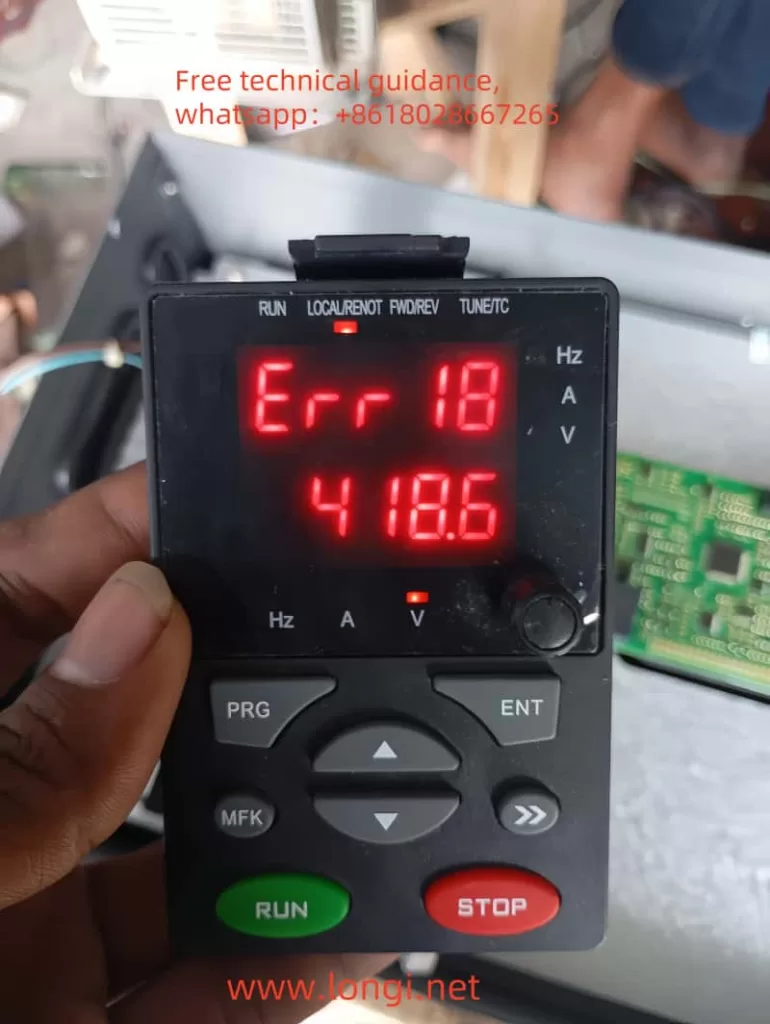
- ERR18: Current Detection Fault
Fault Analysis: This fault may be caused by abnormal Hall devices or drive boards.
Solution:
Replace the Hall devices.
Replace the drive board.
By following this guide, you should be able to better understand and utilize the Haishida HSD260 series VFD. If you encounter any unresolved issues, it is recommended to contact Rongji Electromechanical Technology Co., Ltd. for technical assistance.