
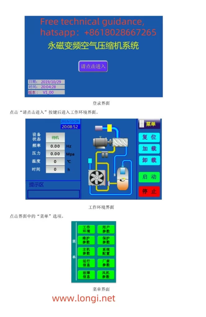
This guide aims to assist users in better understanding and utilizing the Invt GD300-01A-RT Series VFD, a single frequency converter specifically designed for air compressor control, featuring efficiency, ease of use, and reliability. Below is a detailed usage guide.
I. Operating Methods for Controlling Air Compressors
- Wiring Method
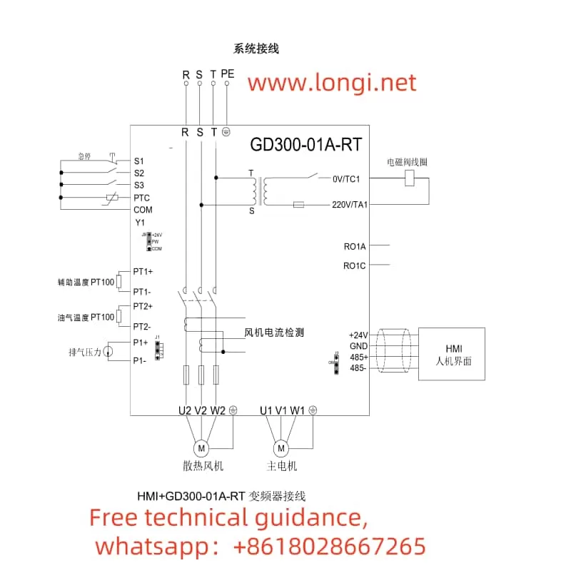
Main Circuit Wiring:
Connect the power input terminals (R, S, T or L1, L2, L3) to the electrical grid.
Connect the motor output terminals (U, V, W) to the main motor of the air compressor.
The grounding terminal PE must be grounded with a grounding resistance of less than 10Ω.
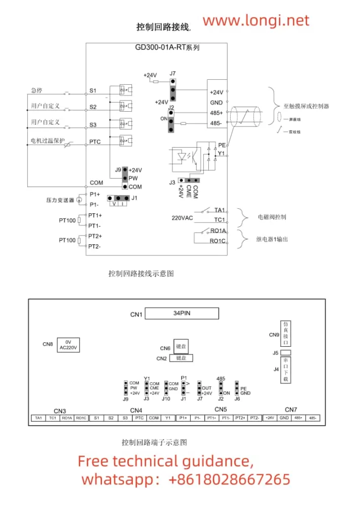
Control Circuit Wiring:
Connect signal lines, such as pressure sensors and temperature sensors, to the corresponding input terminals (e.g., P1+, P1-) as per actual requirements.
Connect external control signals (e.g., start, stop, load, unload) to the respective input terminals (e.g., S1, S2, S3).
If needed, connect fault outputs, alarm outputs, etc., to external devices. - Parameter Settings
Motor Parameter Settings:
Enter the “Main Unit Parameter Settings” interface and set parameters such as motor type, rated power, rated frequency, rated voltage, and rated current based on the actual motor nameplate parameters.
Perform motor parameter self-learning to ensure the VFD can accurately control the motor.
Air Compressor-Specific Parameter Settings:
Set the range and calibration points for pressure sensors and temperature sensors.
Set parameters such as loading pressure, unloading pressure, no-load operating frequency, and minimum loading operating frequency to suit the operational needs of the air compressor.
Set parameters such as fan control mode and maintenance timeout as required.
II. Using External Terminals for Starting and External Potentiometer for Frequency Adjustment
- Wiring Method
External Start Terminal Wiring:
Connect the external start signal (e.g., push-button switch) to the S1 terminal (forward start) and the COM terminal.
For reverse start, connect the signal to the S2 terminal.
External Potentiometer Wiring:
Connect the center tap of the external potentiometer to the AI1 terminal (analog input 1).
Connect the other two terminals of the potentiometer to +10V and GND terminals to provide the required power supply voltage for the potentiometer. - Parameter Settings
Operation Command Channel Settings:
Enter the “Basic Function Group” parameter settings and set P00.01 to 1 (terminal operation command channel).
Frequency Command Selection:
Set P00.06 to 1 (analog P1-setting) to enable external potentiometer frequency adjustment.
III. Setting Password Function and Restoring Factory Settings
- Setting Password Function
Enter the “Human-Machine Interface Group” parameter settings and locate the P07.00 (user password) parameter.
Enter the desired password value (0~65535) and save the settings.
After setting the password, the correct password must be entered for parameter modification. - Restoring Factory Settings
Enter the “Basic Function Group” parameter settings and locate the P00.18 parameter.
Set P00.18 to 1 (restore default values) and save the settings.
The VFD will automatically restore to the factory default parameter settings.
IV. Fault Analysis and Handling Methods
- Fault Code Query
When a fault occurs in the VFD, first check the fault code on the VFD panel.
Refer to the “VFD Faults and Countermeasures” section in the manual based on the fault code to find possible fault causes and corrective actions. - Fault Troubleshooting Steps
Check the power supply and wiring: Ensure normal power input and secure wiring.
Check external control signals: Ensure normal input of external control signals (e.g., start, stop, load, unload).
Check sensor signals: Ensure normal input of signals from pressure sensors, temperature sensors, etc., and correct range and calibration point settings.
Check the motor and load: Ensure normal motor operation and no abnormalities in the load. - Fault Handling Examples
Overcurrent Fault (OC1, OC2, OC3):
Check if the grid voltage is too low.
Check for short circuits or locked rotor phenomena in the motor and load.
Increase the acceleration/deceleration time or select a VFD with a higher power.
Overvoltage Fault (OV1, OV2, OV3):
Check if the input power voltage is too high.
Check for energy feedback phenomena and add energy consumption braking components if necessary.
Undervoltage Fault (UV):
Check if the grid voltage is too low or fluctuating significantly.
By following this usage guide, users can better grasp the operation of the Invt GD300-01A-RT Series VFD dedicated for air compressors, ensuring stable operation of the air compressor system.