
I. Introduction to Inverter Operation Panel Functions
1.1 Function of Operation Panel Buttons
The operation panel of the Hpmont HD20 series inverter is equipped with multiple buttons and indicators for controlling the inverter and displaying its status. The main button functions are as follows:
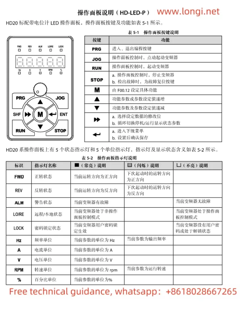
****: Enter or exit programming mode.
****: When controlled via the operation panel, jog start the inverter.
****: When controlled via the operation panel, start the inverter.
****: When controlled via the operation panel, stop the inverter or perform fault reset.
****: Increment the functional parameter or parameter setting value.
****: Decrement the functional parameter or parameter setting value.
****: Select the modification digit of the set data or cyclically switch the display state parameters between stop/run.
****: Enter the submenu or confirm and save the settings.
1.2 Password Function Setting and Unlocking
To prevent unauthorized modifications, the inverter has a user password protection function. The following are the steps for setting, unlocking, and modifying the password:
Password Setting
Press ** to enter programming mode.
Use and to select parameter F01.00.
Press ** to enter password setting mode, and use and to input the desired password value (00000-65535).
After inputting, press ** to confirm and save, then exit programming mode.
Password Unlocking
If prompted to enter a password during operation panel use, press ** to enter password entry mode.
Use and to input the previously set password.
After inputting, press ** to confirm. If the password is correct, unlocking is successful, and operation can continue.
Password Modification
Press ** to enter programming mode.
Use and to select parameter F01.00.
Press ** to enter password modification mode, and use and to input the new password value.
After inputting, press ** to confirm and save, then exit programming mode.
II. Terminal Start/Stop and External Potentiometer Speed Adjustment Methods
2.1 Terminal Start/Stop Wiring and Parameter Setting
Wiring Method
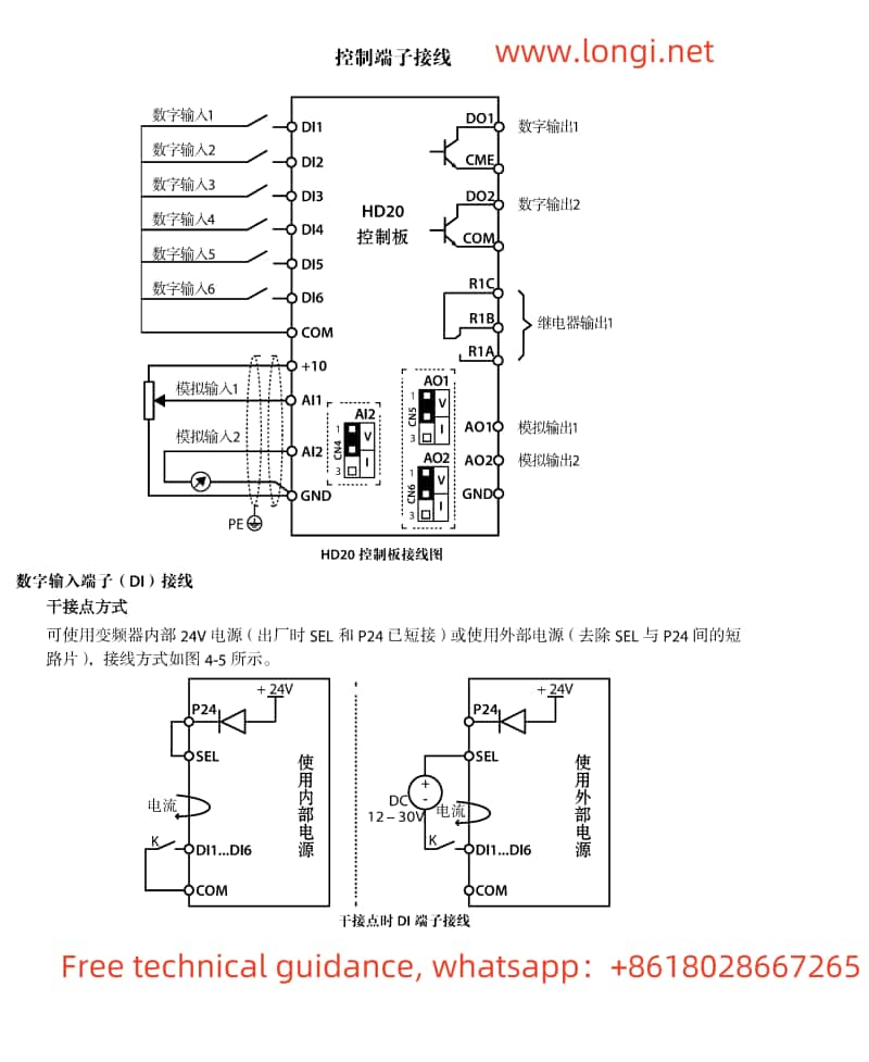
Forward control terminal (DI1): Connect the forward start signal.
Reverse control terminal (DI2): Connect the reverse start signal.
Common terminal (COM): Connect to the other end of DI1 and DI2.
Parameter Setting
Enter programming mode, set parameter F15.00 to 2 (forward function).
Set parameter F15.01 to 3 (reverse function).
Set other relevant parameters as needed, such as setting F00.11 to 1 (terminal operation command channel).
2.2 External Potentiometer Speed Adjustment Wiring and Parameter Setting
Wiring Method
Connect terminal 1 of the external potentiometer to the +10V terminal of the inverter.
Connect terminal 2 of the external potentiometer to the AI1 terminal of the inverter.
Connect terminal 3 of the external potentiometer to the GND terminal of the inverter.
Parameter Setting
Enter programming mode, set parameter F16.01 to 2 (frequency setting channel).
Adjust F16.05 (AI1 offset) and F16.06 (AI1 gain) as needed to calibrate the speed adjustment range.
Ensure F00.10 is set to 3 (analog setting) to use the external potentiometer for speed adjustment.
III. Analysis and Solutions for Inverter Fault Codes
3.1 Common Fault Codes and Causes
E0001: Overcurrent protection. Possible causes include motor stall, excessive load, or incorrect parameter settings.
E0007: Overvoltage speed loss. Possible causes include excessively short deceleration time settings or excessive load inertia.
E0015: Input phase loss. Possible causes include input power phase loss or loose wiring.
E0016: Output phase loss. Possible causes include motor or cable damage.
E0017: Inverter overload. Possible causes include excessive load or poor heat dissipation.
3.2 Solutions
E0001: Check if the motor and load are normal, adjust parameters F09.07 (motor torque boost) and F09.09 (motor slip compensation gain).
E0007: Increase deceleration time, adjust parameters F19.18 (overvoltage speed loss function selection) and F19.19 (overvoltage speed loss point).
E0015: Check the input power supply and wiring to ensure normal three-phase power.
E0016: Check motor and cable connections to ensure no damage or looseness.
E0017: Check if the load is excessive, improve heat dissipation conditions, adjust parameters F20.01 (overload pre-alarm detection level) and F20.02 (overload pre-alarm detection time).
Summary
This operation guide provides a detailed introduction to the functions of the operation panel, wiring and parameter settings for terminal start/stop and external potentiometer speed adjustment methods, as well as analysis and solutions for common fault codes of the Hpmont HD20 series inverter. By following this guide, users can smoothly operate and maintain the inverter, ensuring normal equipment operation. During operation, please ensure safety and avoid electric shock and other potential risks. For complex issues, please contact Longi electrical technicians for assistance.