
- Operation Methods for Basic Menus
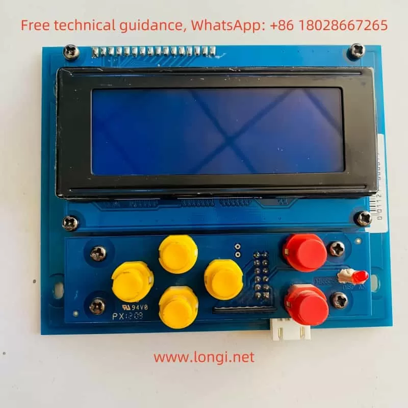
The operation of the MICOVERT 2003 series inverter from Michael is primarily completed through the Handheld Programmer HPG60. The HPG60 is equipped with an LCD display capable of showing 4 lines of text, 6 buttons, and a red LED indicator. Below are the operation methods for the basic menus:
1.1 Entering Menus
Selecting Main Menu: Use the “LEFT” or “RIGHT” buttons to choose from 8 main menus, such as “Speed”, “Speed Curve”, “Start/Stop”, etc.
Entering Submenu: Press the “DOWN” button to enter the submenu of the selected main menu.
Selecting Parameters: In the submenu, use the “DOWN” or “UP” buttons to scroll through and select parameters.
1.2 Setting Parameters
Changing Parameter Values: Use the red “UP” or “DOWN” buttons to select new parameter values.
Saving or Exiting: If the parameter change is correct, press the “ENTER” key to save the new value; if you need to discard the change, press the “ESC” key to exit.
1.3 Start/Stop Menu Settings
The Start/Stop menu is used to set parameters related to the start and stop of the inverter, such as start delay and braking ramp.
Start Delay: Adjusts the time for the motor to start with the brake on to avoid abnormalities caused by delays in contactor and control system actions. The setting range is 0-1000ms.
Braking Ramp: Adjusts the deceleration ramp from V0 speed to zero speed to improve stopping accuracy and reduce vibration. The setting range is 0.01-1.00 m/s².
1.4 Speed Menu Settings
The speed menu is used to set various operating speeds of the inverter, including re-leveling speed, inspection speed, creep speed, medium speed, and high speed.
Re-leveling Speed (Vn): The setting range is 0.5-100 r.p.m., used for re-leveling due to position changes caused by wire rope elongation after elevator unloading.
Inspection Speed (Vi): The setting range is 10-1500 r.p.m., used for inspection operation on the car roof.
Creep Speed (V0): The setting range is 1-100 r.p.m., used for deceleration before elevator stopping.
Medium Speed (V1), High Speed (V2/V3): The setting range is 10-3000 r.p.m., used for elevator operation at different speed segments.
- Input and Output of Control Signals
2.1 Input of Control Signals
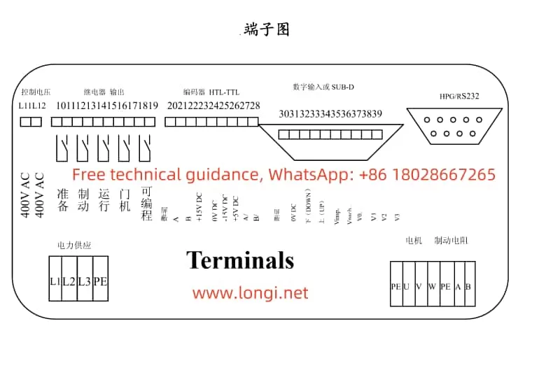
The input of control signals is mainly achieved through various signal terminals on the inverter. Below are the functions and setting methods of some key signal terminals:
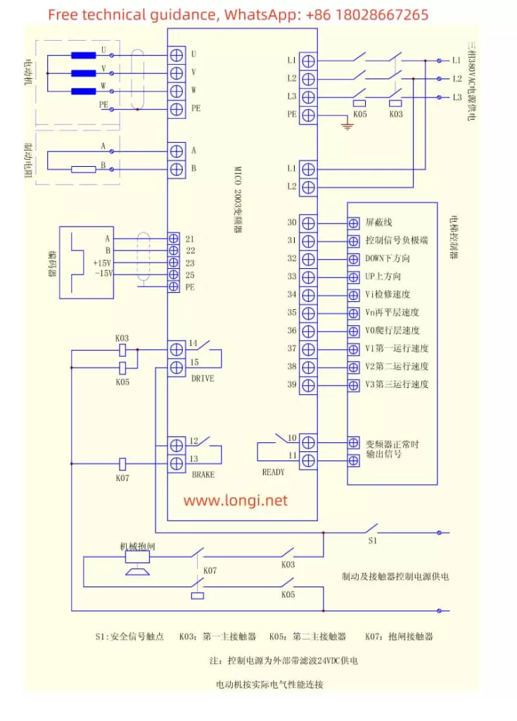
Direction Signals: Include “UP” (up direction) and “DOWN” (down direction) signal terminals. When starting the inverter, direction commands and operation commands need to be given simultaneously.
Inspection Speed Signal (Vinsp): Used to set the inspection speed. When operating at inspection speed, the operation command and direction command need to be withdrawn simultaneously.
Speed Signals (V0, V1, V2, V3): Used to set creep speed, medium speed, and high speed respectively.
2.2 Output of Control Signals
The inverter is equipped with multiple output relays for controlling different functions of the elevator. Below are the functions of some key output relays:
Ready Relay: Engages after the inverter completes its self-check, used for elevator control warning.
Brake Relay: Engages 0.5 seconds after the direction command and speed command are given, causing the mechanical brake contactor to engage.
Operation Relay: Engages when the direction command and speed command are given, and releases 0.5 seconds after the motor reaches zero speed.
- Multi-Speed Operation
The MICOVERT 2003 inverter supports multi-speed operation. By setting different speed parameters (V0, V1, V2, V3), smooth acceleration and deceleration of the elevator at different stages can be achieved. For example, use lower speeds (V0 or V1) during the elevator start-up phase, higher speeds (V2 or V3) during the stable operation phase, and decelerate to creep speed (V0) again during the stopping phase. - Encoder Interface and Settings
The MICOVERT 2003 inverter supports various encoder interfaces, including HTL level encoder, TTL level encoder, Resolver interface, absolute encoder, etc. Below are the basic steps for encoder wiring and settings:
4.1 HTL Level Encoder
Wiring: Connect the A phase, B phase, +15VDC, 0VDC, and shield wire of the encoder to the corresponding terminals of the inverter.
Setting: In the drive menu, select the encoder type as “HTL” and enter the number of pulses per revolution.
4.2 TTL Level Encoder
Wiring: Connect the A phase, B phase, +5VDC, 0VDC, and shield wire of the encoder to the corresponding terminals of the inverter.
Setting: In the drive menu, select the encoder type as “TTL” and enter the number of pulses per revolution.
4.3 Resolver Interface
Wiring: Use the dedicated conversion board RES01 to connect the output signals (SINUS and COSINUS) of the Resolver to the conversion board, and then connect the conversion board to the corresponding terminals of the inverter.
Setting: In the drive menu, select the encoder type as “Resolver” and enter the relevant parameters.
4.4 Absolute Encoder
Wiring: Use the dedicated absolute conversion board ABS01 to connect the output signals of the absolute encoder to the conversion board, and then connect the conversion board to the corresponding terminals of the inverter.
Setting: In the drive menu, select the encoder type as the corresponding absolute encoder type (e.g., SSI, ENDAT), and enter the relevant parameters.
- Fault Code Identification and Solutions
When the inverter malfunctions, the LCD display will show the corresponding error code. Users need to take appropriate solutions based on the error code. Below are some common fault codes and their handling methods:
Error 1 (IPM Overcurrent): Check if the motor parameters are correct or if the IPM module is damaged.
Errors 2-4 (U/V/W Phase Overcurrent): Similarly, check the motor parameters or IPM module.
Error 5 (Heat Sink Overtemperature): Check if the cooling system is working normally or reduce the load.
Error 6 (Intermediate Circuit Voltage Too High): Check if the braking resistor is connected normally or damaged.
Error 7 (Intermediate Circuit Voltage Too Low): Check if the main power supply voltage is too low.
Errors 8-9 (Operation Contactor Not Engaged or Main Power Supply Missing a Phase): Check if the contactor or main power supply connection is normal.
Errors 10-16: Involve issues such as missing direction commands, conflicting direction commands, no pulse signal from the encoder, etc. Check the relevant signals and wiring according to the specific situation.
By carefully reading and following the above instructions, users can better operate and maintain the MICOVERT 2003 series inverter from Micor, ensuring its stable operation and efficient performance.