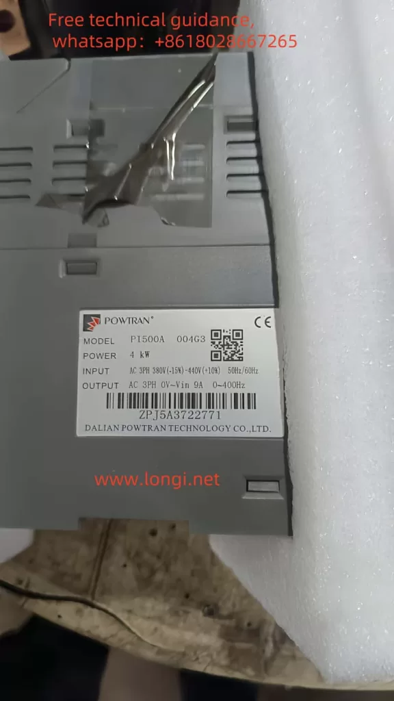
I. Operation Methods for Powtran Inverter PI500 Series
1. Panel Start and Stop
The Powtran Inverter PI500 series features an easy-to-use operation panel, allowing users to start and stop the inverter via panel buttons. Specific steps are as follows:
- Start: Press the “Run” button on the operation panel to start the inverter. In keyboard operation mode, this button is used to initiate running.
- Stop: Press the “Stop/Reset” button on the operation panel to stop the inverter. In keyboard operation mode, this button is used to halt running; in fault alarm states, it can be used for reset operations.

2. Debugging Steps
Proper debugging of the inverter is crucial to ensure its normal operation. The following is a general debugging process:
- Check Connections: Ensure all power and motor cable connections are correct and secure.
- Set Parameters: Configure various inverter parameters, such as control mode, acceleration and deceleration times, frequency source, etc., via the operation panel or remote communication.
- Motor Parameter Self-Learning: In vector control mode, motor parameter self-learning is required to ensure accurate motor control by the inverter.
- Jog Operation: Perform a jog operation to observe whether the motor’s rotation direction is correct. If abnormal, adjust the motor wiring phase sequence.
- Actual Operation: After confirming everything is correct, conduct an actual operation test to observe whether the inverter’s output frequency, current, voltage, and other parameters are normal.

II. Inverter Fault Codes and Meanings
The Powtran Inverter PI500 series provides extensive fault codes to help users quickly locate issues. Here are some common fault codes and their meanings:
- Err.01: Inverter unit protection, possibly caused by output circuit short circuit, module overheating, etc.
- Err.02: Acceleration overcurrent, possibly caused by too short acceleration time, low voltage, etc.
- Err.03: Deceleration overcurrent, possibly caused by too short deceleration time, sudden load changes, etc.
- Err.04: Constant speed overcurrent, possibly caused by excessive load, motor stall, etc.
- Err.05: Acceleration overvoltage, possibly caused by lack of braking unit, high input voltage, etc.
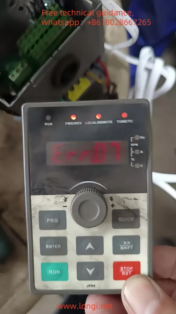
- Err.07: Constant speed overvoltage, possibly caused by external force dragging the motor during operation, high input voltage, etc.
III. ERR07 Fault Analysis
The Err.07 fault code indicates constant speed overvoltage, meaning the inverter detects excessively high output voltage during constant speed operation. Possible causes include:
- High Input Voltage: When the input voltage exceeds the rated voltage range of the inverter, it may lead to excessively high output voltage.
- External Force Dragging the Motor: During constant speed operation, if the motor is dragged to rotate by an external force, it may cause the inverter’s output voltage to rise.
- Braking Unit Failure: If the inverter is not equipped with a braking unit or the braking unit fails, it may not effectively dissipate the motor’s regenerative energy during deceleration, resulting in voltage rise.
IV. Solutions for ERR07 Fault
1. Reset or Adjust Inverter Parameters
- Check Input Voltage: Ensure the input voltage is within the rated voltage range of the inverter. If the input voltage is too high, measures must be taken to reduce it.
- Check External Force Dragging: Eliminate the possibility of external force dragging the motor and ensure the motor operates in a free state.
- Check Braking Unit: If the inverter is not equipped with a braking unit, it should be installed as per actual needs; if the braking unit fails, it should be promptly replaced.
- Adjust Parameters: Adjust relevant inverter parameters based on actual conditions, such as acceleration and deceleration times, overvoltage protection thresholds, etc.
2. Replace Boards or Circuits
If the Err.07 fault cannot be resolved after the above adjustments, it may be necessary to replace internal boards or circuits of the inverter. Specific steps are as follows:
- Power Off: First, disconnect the inverter’s power supply to ensure safety.
- Disassemble the Enclosure: Use appropriate tools to disassemble the inverter’s enclosure to expose the internal circuitry.
- Locate Faulty Components: Based on the fault code and circuit diagram, locate the potentially faulty board or circuit.
- Replace Components: Remove the faulty board or circuit and replace it with a new one. Be careful not to damage other components during the replacement process.
- Assemble the Enclosure: After replacement, reinstall the inverter’s enclosure.
- Power On and Test: Power on the inverter again and conduct tests to verify whether the fault has been resolved.
V. Precautions
- Before performing any maintenance or replacement operations, ensure the inverter is powered off and follow relevant safety operating procedures.
- When replacing components, use components of the same model and specifications as the original to ensure the normal operation of the inverter.
- If unfamiliar with the internal structure and working principle of the inverter, seek help from professional technicians.
By following the above steps, users can effectively resolve the Err.07 fault in the Powtran Inverter PI500 series and ensure the normal operation of the inverter.
