The Yaskawa Inverter A1000 Series is a high-performance vector control inverter widely used in various industrial control applications. This document aims to provide users with a detailed guide, covering the function explanation of the operation panel, password setting and cancellation, parameter initialization settings, external terminal start/stop and potentiometer speed adjustment settings, as well as common fault codes and troubleshooting methods.

I. Function Explanation of the Operation Panel (Operator)
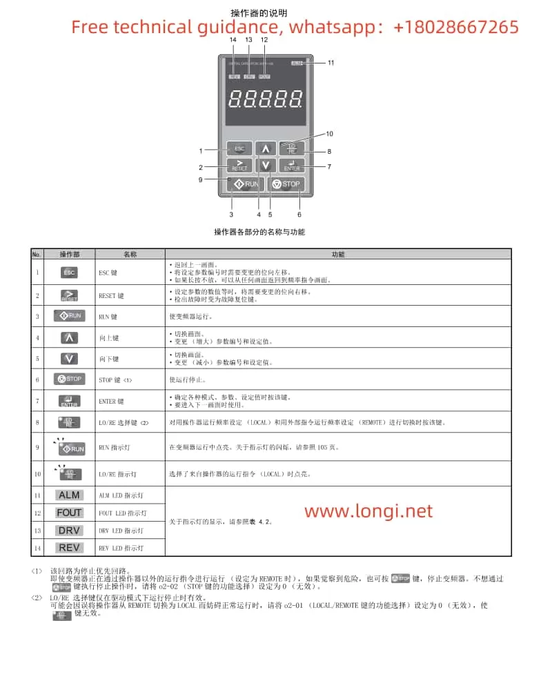
The operation panel of the Yaskawa Inverter A1000 Series integrates multiple functions, facilitating user parameter settings and status monitoring. Below are the main functions of the operation panel:
- Display and Operation: The operation panel features an LED display and multiple operation keys, including the “LOCAL/REMOTE” key and the “STOP” key, allowing users to perform local or remote operations and stop the inverter.
- Password Setting and Cancellation:
- Password Setting: Enter the parameter setting mode and set the password by configuring A1-04 (Password) and A1-05 (Password Setting). The specific steps are: First, press the “ESC” key to enter the parameter setting mode, then select A1-05 and input the password value, and finally press the “ENTER” key to confirm.
- Password Cancellation: To cancel the set password, set A1-04 (Password) to the same value as A1-05 (Password Setting), then re-enter the parameter setting mode and set both A1-04 and A1-05 to 0.
- Parameter Initialization Settings: Set A1-03 (Initialization) to choose different initialization methods. Common options include:
- 1110: Initializes based on user settings, restoring parameters to user-saved values.
- 2220: Initializes for 2-wire sequential control, restoring factory settings for 2-wire sequential control.
- 3330: Initializes for 3-wire sequential control, restoring factory settings for 3-wire sequential control.
- 5550: Resets oPE04, used for parameter reset after replacing the detachable terminal block.
II. External Terminal Start/Stop and Potentiometer Speed Adjustment Settings
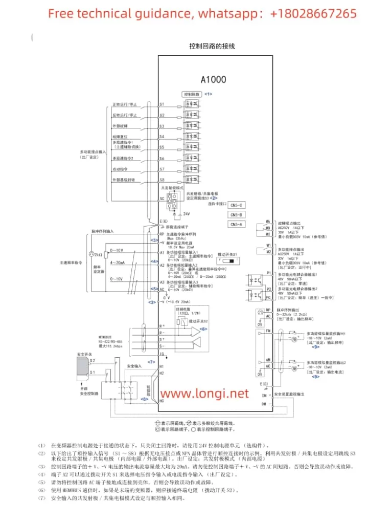
To enable external terminal start/stop and potentiometer speed adjustment functions for the Yaskawa Inverter A1000 Series, the following parameter and wiring settings are required:
- Parameter Settings:
- Set b1-01 (Run Command Selection 1) to 2, selecting external terminal run commands.
- Set b1-02 (Run Command Selection 2) to 0, selecting the 2-wire sequential control mode for forward/stop and reverse/stop (or select other modes as needed).
- Set H1-01 and H1-02 to 40 and 41, respectively, assigning the S1 and S2 terminals as input for forward and reverse run commands.
- Wiring Settings:
- Connect the external start/stop buttons to the S1 and S2 terminals.
- Connect the center tap of the potentiometer to the common terminal of the inverter (e.g., 0V), and connect the ends of the potentiometer to the analog input terminals of the inverter (e.g., A1 and +V or -V) to achieve potentiometer speed adjustment.

III. Common Fault Codes and Troubleshooting Methods
The Yaskawa Inverter A1000 Series may encounter various faults during operation. Below are some common fault codes, their meanings, and troubleshooting methods:
- oL1 (Motor Overload):
- Meaning: The motor current exceeds the rated value, triggering the overload protection.
- Troubleshooting: Check if the motor load is too heavy, adjust the load or increase the motor capacity; check the motor wiring for correctness to avoid line-to-line shorts; check the inverter parameter settings to ensure the motor parameters match the actual motor.
- Uv1 (Main Circuit Undervoltage):
- Meaning: The main circuit DC voltage is lower than the set value.
- Troubleshooting: Check if the power supply voltage is stable and within the allowable range; check the power wiring for firmness to avoid poor contact; check if the internal capacitors of the inverter are aged or damaged.
- oH1 (Inverter Overheat):
- Meaning: The internal temperature of the inverter is too high, triggering the overheat protection.
- Troubleshooting: Check the installation environment of the inverter to ensure adequate ventilation; check if the inverter heat sink is clean and free of dust accumulation; check if the cooling fan is working properly and replace it if faulty.
- oPE03 (Improper Selection of Multi-function Input):
- Meaning: There is a conflict or error in the function assignment of the multi-function input terminals.
- Troubleshooting: Check the parameter settings of H1-01 to H1-08 to ensure the function assignment of each terminal is correct and without duplication; check if any unused terminals have been assigned functions mistakenly.
- Er-11 (Motor Speed Fault):
- Meaning: During rotary self-learning, the motor speed is abnormal.
- Troubleshooting: Check the connection between the motor and the inverter for correctness; check the wiring and settings of the PG (encoder); re-perform self-learning with the motor and mechanical system connected.
The above are only some common fault codes and their troubleshooting methods. In actual use, other faults may occur. Users should refer to the fault code table in the inverter user manual and take corresponding measures based on specific fault codes and meanings. Additionally, regular maintenance and inspection of the inverter are important means to prevent faults.
