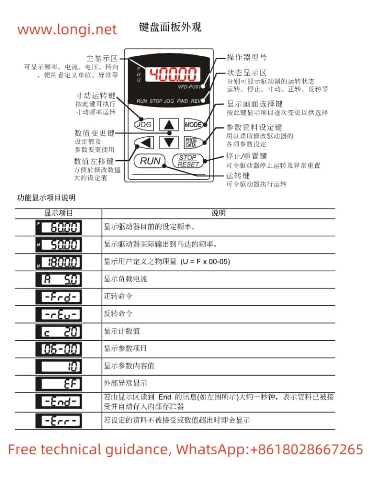
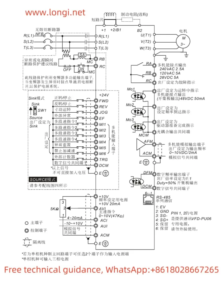
I. Operating Panel Function Description and Parameter Settings
1. Operating Panel Function Description
The Delta Inverter VFD-B series features an intuitive operating panel with various functions and a display screen. The panel includes buttons such as RUN, STOP, ▲ (frequency increase), ▼ (frequency decrease), MODE, and an LCD display to show current operating status and parameter settings.

2. Restoring Factory Defaults
To restore the inverter to its factory default settings, follow these steps:
- Enter Parameter Setting Mode: Press the MODE button to enter parameter setting mode.
- Select User Parameters: Use the ▲ and ▼ buttons to select parameter group 00 (User Parameters).
- Select Parameter Reset: Continue using the ▲ and ▼ buttons to select parameter 00-02 (Parameter Reset Setting).
- Set Factory Defaults: Set the value of parameter 00-02 to 09 or 10, corresponding to different voltage and frequency factory default settings.
- Save and Exit: After confirming the settings, press the DATA button to save and exit parameter setting mode.
3. Setting and Removing Passwords
To protect the inverter’s parameter settings from unauthorized changes, you can set a password:
- Enter Password Setting: In parameter setting mode, select User Parameters in parameter group 00, then find parameter 00-08 (Parameter Protection Password Setting).
- Enter Password: Use the ▲ and ▼ buttons to input the desired password (00~65535).
- Confirm Password: Enter the same password again to confirm.
To remove an existing password, simply set the value of parameter 00-08 back to 00.
II. Terminal Start and External Potentiometer Speed Control Settings
To configure the inverter for terminal start and external potentiometer speed control, you need to set specific parameters and connect certain terminals:
1. Parameter Settings
- First Operation Command Source Setting: Set parameter 02-01 to 01, indicating that the operation command is controlled by external terminals.
- First Frequency Command Source Setting: Set parameter 02-00 to 01, indicating that the frequency command is controlled by the analog signal (0~10V) input from the external terminal AVI.
- Multi-function Input Command Setting: Depending on your needs, set parameters 04-04 to 04-09 to corresponding functions such as forward rotation, reverse rotation, start, stop, etc.
2. Terminal Connections
- Power Connection: Connect the inverter’s power terminals R, S, T to the three-phase AC power supply.
- Motor Connection: Connect the inverter’s output terminals U, V, W to the three-phase induction motor.
- Start and Stop Terminal Connection: Connect the external start button between the FWD terminal and the DCM terminal, and connect the stop button between the REV terminal and the DCM terminal (note that the connection method depends on the two/three-wire mode selection setting).
- External Potentiometer Connection: Connect the output of the external potentiometer between the AVI terminal and the GND terminal for speed control.

III. Fault Codes, Their Meanings, and Solutions
The Delta Inverter VFD-B series will display corresponding fault codes when a fault occurs, allowing users to quickly locate the problem. Below are some common fault codes, their meanings, and solutions:
- OC (Overcurrent): Indicates that the output current of the inverter exceeds the rated value.
- Solution: Check if the motor is overloaded, verify the motor wiring is correct, and adjust the acceleration and deceleration time parameters.
- OV (Overvoltage): Indicates that the DC bus voltage of the inverter is too high.
- Solution: Check if the input power supply voltage is too high, ensure the braking resistor is connected correctly, and adjust the overvoltage protection parameters.
- OH (Overheat): Indicates that the internal temperature of the inverter is too high.
- Solution: Check if the inverter installation environment is well-ventilated, ensure the cooling fan is working properly, reduce the load, or increase cooling measures.
- OL (Overload): Indicates that the motor is overloaded.
- Solution: Check if the motor is operating under overload conditions, adjust the load, or increase the motor capacity.
- EF (External Fault): Indicates that an external fault signal has been input.
- Solution: Check the source of the external fault signal and resolve the external fault.
- CF (Communication Fault): Indicates a communication anomaly.
- Solution: Check if the communication lines are connected correctly and ensure the communication parameter settings are correct.
By following these steps, users can effectively use the Delta Inverter VFD-B series, including operating the panel, setting parameters, configuring functions, and troubleshooting faults. These operations will help users better control and maintain the inverter, ensuring its normal operation.
