I. Introduction to MIKOM Inverter MV Series Operation Panel Functions
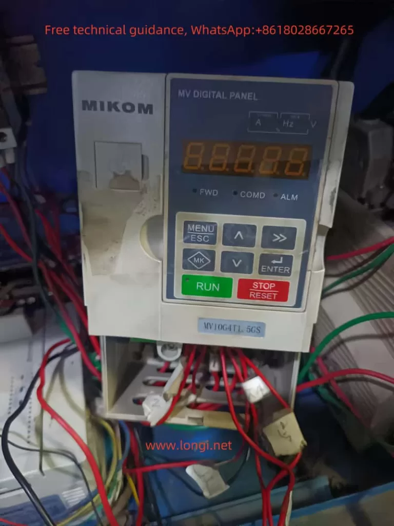
The MIKOM Inverter MV series features a comprehensive operation panel with LED display, indicators, multi-function MK key, programming keys, increment/decrement keys, stop/reset key, and run key.

1. LED Display Area
- Displays current set frequency, output frequency, output voltage, output current, and other parameters.
2. Indicators
- FWD: Forward/Reverse Indicator. Lit indicates reverse operation; off indicates forward operation or stop.
- COMD: Command Channel Indicator. Lit indicates operation panel control; flashing indicates serial communication control; off indicates terminal control.
- ALM: Fault Indicator. Lit indicates fault status; flashing indicates alarm status.
- RUN: Run Status Indicator. Lit indicates running; off indicates stop.
3. Function Keys
- MK Key: Multi-function key, whose function is defined by parameter P50.03.
- Programming Key: Enters or exits the menu.
- Increment/Decrement Keys: Increment or decrement data or function codes.
- Stop/Reset Key: Stops operation during running and resets during fault alarm.
- Run Key: Initiates operation in keyboard operation mode.
4. Restoring Factory Defaults
- Set parameter P50.20 to 22, then press the run key to restore factory defaults.
5. Panel Start/Stop and Speed Adjustment Settings
- Set P00.01 to 0 to select the operation panel control command channel.
- Use the increment and decrement keys on the operation panel for speed adjustment.

II. Terminal Start/Stop and Potentiometer Speed Adjustment Settings
1. Terminal Connections
- Terminals to be connected include: run command terminals (e.g., FWD, REV), speed reference terminals (e.g., AI1, AI2), and common terminals (e.g., COM).
2. Parameter Settings
- Set P00.01 to 1 to select the terminal run command channel.
- Set P00.02 to the corresponding analog input channel (e.g., AI1 given).
- Configure the functions of each terminal as needed in P10 group parameters.
3. Speed Adjustment Settings
- Connect an external potentiometer to the speed reference terminal (e.g., AI1) and common terminal (e.g., COM) to adjust the speed by turning the potentiometer.
III. Fault Codes and ER.03 Fault Analysis
1. Fault Codes
The MIKOM Inverter MV series has comprehensive fault protection functions. Common fault codes include:
- ER.01: Overcurrent Protection
- ER.02: Overvoltage Protection
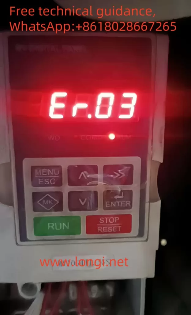
- ER.03: Constant Speed Overcurrent
- ER.04: Undervoltage Protection
- ER.05: Overload Protection
- ER.06: Overheat Protection
- ER.07: Module Protection
- ER.08: Phase Loss Protection
- ER.09: External Reference Lost
- ER.10: Excessive Speed Deviation
2. ER.03 Fault Analysis
ER.03 indicates a constant speed overcurrent fault, typically occurring when the inverter’s output current exceeds the rated current limit. This fault can be caused by:
- Excessive motor load or mechanical blockage.
- Incorrect motor parameter settings, leading to excessive inverter output current.
- Inverter internal drive board fault, such as poor IGBT conduction or defective drive optocouplers.
3. Handling and Repair Methods
- Check Load and Mechanical Parts: Ensure the motor load is normal and there is no mechanical blockage.
- Check Motor Parameter Settings: Ensure motor parameters (e.g., rated power, rated current) are set correctly.
- Check Drive Board: If the above two items are normal, the fault may be in the inverter’s internal drive board. Professional maintenance personnel are required for inspection and repair, replacing damaged IGBTs or drive optocouplers as necessary.
When handling ER.03 faults, always ensure power-off operation to avoid electrical shock hazards. Regular maintenance and inspection of the inverter are recommended to promptly identify and address potential faults, ensuring the normal operation of the inverter.
The MIKOM Inverter MV series is widely used in multiple industries due to its high performance and reliability. By correctly setting and operating panel functions, reasonably wiring and configuring parameters, and promptly and effectively handling faults and maintenance, the performance advantages of the inverter can be fully utilized, improving production efficiency and equipment reliability.
