I. Achieving Constant Pressure Water Supply with Single Pump Control
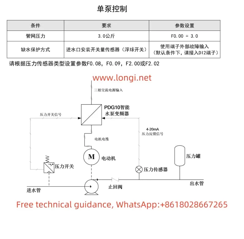
In single pump control mode, the PDG10 series SANJ INVERTER automatically adjusts the speed of the water pump motor by setting the pipe network pressure value, thereby maintaining a constant water supply pressure. Below are the steps to achieve constant pressure water supply:

1. Wiring
- Main Circuit Wiring: Connect the three-phase power supply to the R, S, T terminals of the inverter and the motor to the U, V, W terminals, ensuring the grounding terminal is reliably grounded.
- Control Circuit Wiring: Depending on requirements, connect the pressure sensor to the AI1 or AI2 terminal and set the F2.00 or F2.02 parameter according to the sensor type. If using external start/stop control, connect the start and stop signals to the DI1 and DI2 terminals.
2. Parameter Settings
- Pressure Setting: Set the target pressure value through the F0.00 parameter. For example, to achieve a pipe network pressure of 3.0 kg, set F0.00=3.0.
- Start Mode: If using external start/stop control, set F0.05=1 (terminal start/stop).
- Sensor Settings: Set F0.08 (sensor range), F0.09 (sensor feedback channel selection), and F2.00 or F2.02 (sensor feedback type selection) according to the pressure sensor type.
- Operating Mode: Set F0.15=0 to select the constant pressure control mode.
- Other Parameters: Set acceleration time (F0.18) and deceleration time (F0.19) parameters according to actual needs.

II. One-to-Two Timed Rotation Control
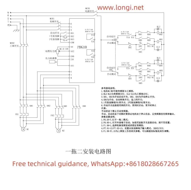
In one-to-two timed rotation control mode, one inverter alternately controls two water pump motors to achieve timed rotation. Below are the implementation steps:
1. Wiring
- Main Circuit Wiring: Connect the output terminals of the inverter to the U, V, W terminals of the two water pump motors respectively.
- Control Circuit Wiring: Connect the pressure sensor to the AI1 or AI2 terminal and connect the relay output terminals of the inverter (e.g., T1A/T1B and T2A/T2B) to the control circuit of the contactors to achieve water pump rotation control.
- Frequency Control: If frequency backup is required, connect the frequency power supply to the corresponding contactor and control the contactor’s engagement and disengagement through the inverter’s relay output.
2. Parameter Settings
- One-to-Two Mode: Set F0.20=7 to select the one-to-two mode.
- Rotation Mode: Set F1.08=1 to select the rotating variable frequency pump mode.
- Pump Addition and Reduction Parameters: Set F1.09 (bias pressure for adding frequency pump), F1.10 (delay time for adding frequency pump), F1.11 (bias pressure for reducing frequency pump), F1.12 (delay time for reducing frequency pump), etc., according to actual needs.
- Rotation Time: Set F1.05 to define the interval time for timed rotation of the main and auxiliary pumps.
- Other Parameters: Set PID parameters (e.g., F3.00 proportional gain, F3.01 integral time) and other related parameters according to actual needs.

III. Multi-Pump Networking Scheme
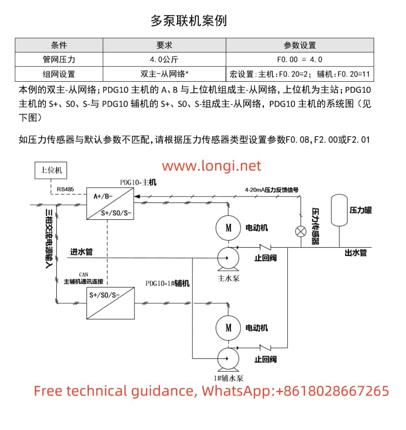
The PDG10 series SANJ INVERTER supports multi-pump networking control via RS485 (MODBUS) or CAN bus. Below are the implementation steps:
1. Wiring
- RS485 Communication Wiring: Connect the A+/B- terminals of the inverter to the RS485 communication ports of the host computer or other inverters using twisted pair or shielded cable.
- CAN Communication Wiring: Connect the S+/S0/S- terminals of the inverter to the CAN communication ports of other inverters using twisted pair or shielded cable.
2. Parameter Settings
- Communication Parameters: Set F8.00 (local address), F8.01 (RS485 communication baud rate setting), F8.02 (RS485 data format setting), etc., to ensure normal communication between inverters.
- Multi-Pump Networking Mode: Set F0.20 (multi-pump macro debugging function) to select the corresponding multi-pump networking mode (e.g., master, slave, etc.).
- Network Mode: Set F1.02 (multi-pump network mode selection) to define the network role of each inverter (e.g., master, slave, etc.).
- Slave Settings: Set F1.00 (multi-pump networking communication address) on the slave to ensure each slave has a unique address.
- Other Parameters: Set the number of multi-pump networking slaves (F1.03), multi-pump operation mode (F1.04), etc., according to actual needs.
IV. Fault Codes and Solutions
The PDG10 series SANJ INVERTER features comprehensive fault protection functions. When a fault occurs, the corresponding fault code will be displayed. Below are some common fault codes, their meanings, and solutions:
- E002: Overcurrent during acceleration. Possible causes include too fast acceleration, low grid voltage, or undersized inverter. Solutions include increasing acceleration time, checking the input power supply, or selecting a larger inverter.
- E015: External fault. Possible causes include activation of the external fault input terminal. The solution is to check whether the external device input is normal.
- E027: Water shortage alarm. Possible causes include abnormal water pressure/level, disconnected or poorly contacted sensors, etc. Solutions include checking the water inlet pressure of the water pump, sensor installation and wiring, and related parameter settings.
- E050: Multi-pump communication error. Possible causes include abnormal multi-pump communication or duplicate networking addresses. Solutions include power cycling, checking CAN networking communication address settings, or seeking service support.
When a fault occurs, first refer to the fault code to identify the possible cause and follow the corresponding solution. If the problem cannot be resolved, contact a professional technician for further inspection and repair.
Summary
The PDG10 series SANJ INVERTER, as a dedicated product for water pump control, features powerful functionality, easy operation, and high reliability. Through reasonable wiring and parameter settings, it can achieve various application modes such as single-pump constant pressure water supply, one-to-two timed rotation control, and multi-pump networking control. Additionally, the inverter provides comprehensive fault protection functions and fault code prompts, facilitating fault diagnosis and handling for users. It is hoped that this usage guide will help users better understand and use the PDG10 series SANJ INVERTER.
