I. Introduction to the Operating Panel Functions and Password Settings
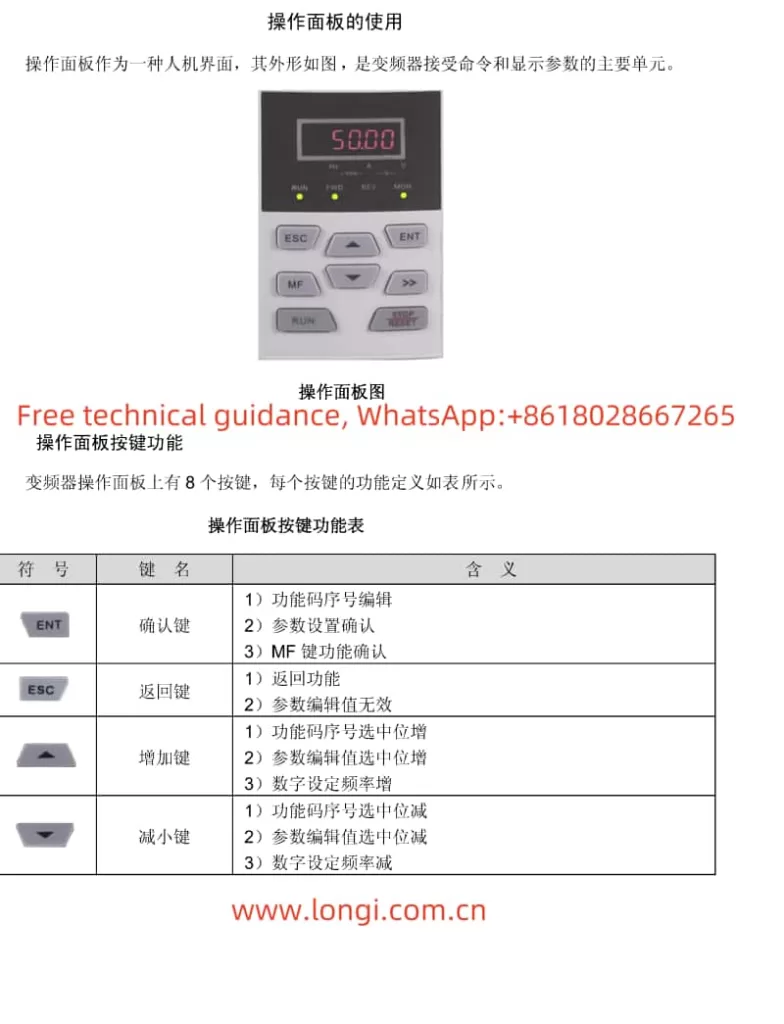
The operating panel of the GTAKE Inverter GK600 series serves as its core human-machine interface, providing parameter setting, operational status display, and more. The primary indicators and button functions on the operating panel are as follows:
- Indicators: Include frequency indication, current indication, voltage indication, speed indication, etc., used to display the current operating status of the inverter.
- Buttons: Include RUN, STOP/RESET, MF (multi-function button), etc., used to control the start, stop, and parameter settings of the inverter.

Setting and Removing Passwords
To protect the inverter parameters from unauthorized changes, users can set passwords to restrict access. The specific operations are as follows:
- Setting a Password:
- Enter function code A0-00, input a four-digit non-zero password, and press ENT to confirm.
- Re-enter the same password within 10 seconds to confirm, and “P-Set” will be displayed upon successful setting.
- If there are no button operations within 5 minutes or after a complete power-off and power-on cycle, the password will automatically take effect.
- Removing a Password:
- Enter function code A0-00 and input the original four-digit password.
- Input 0000 twice and press ENT to confirm, and the password will be cleared successfully with “P-Set” displayed.
Initializing Parameters
Users can restore the inverter parameters to their factory settings through the initialization function. The specific operations are as follows:
- Enter function code A0-03 and set it to 2 (restore all function code group parameters to factory settings, excluding motor parameters) or 3 (restore all function code group parameters to factory settings, including motor parameters), then press ENT to confirm and the parameters will be initialized.
II. Terminal Forward/Reverse Start/Stop and Potentiometer External Speed Regulation
Terminal Forward/Reverse Start/Stop
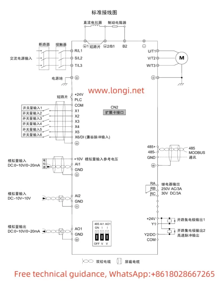
The GK600 series inverter supports forward/reverse start/stop functions through terminals. The specific settings and wiring are as follows:
- Parameter Settings:
- Enter the C0 group function codes and set the functions of terminals X1, X2, X3, and X4 to forward jog, reverse jog, forward run, reverse run, etc.
- Set C0-00 to 0 (edge trigger + level valid) or 1 (level valid) based on actual needs.
- Wiring:
- Connect the external control signals to the corresponding forward/reverse start/stop terminals.
Potentiometer External Speed Regulation
Speed regulation can be achieved through an external potentiometer. The specific settings and wiring are as follows:
- Parameter Settings:
- Enter the b0 group function codes and set the frequency main given method b0-01 to 2 (analog input AI1).
- Ensure that the AI1 terminal is correctly connected to the potentiometer, and select voltage or current input via the jumper.
- Wiring:
- Connect the three pins of the potentiometer to the positive, negative, and ground terminals of the AI1 terminal.

III. Swing Frequency Function and Length Control
Swing Frequency Function
The swing frequency function allows the inverter to operate with fluctuating frequencies within a set range, suitable for applications requiring periodic frequency changes. The specific parameter settings are as follows:
- Enter the F3 group function codes and set F3-00 to 1 (select swing frequency function).
- Set parameters such as F3-01 swing frequency operation mode, F3-02 swing frequency preset, F3-03 swing frequency preset hold time, and F3-04 swing frequency amplitude.
Length Control
Length control automatically stops the inverter based on a set length. The specific wiring and parameter settings are as follows:
- Wiring:
- Connect the length counting pulse signal to the X6/DI terminal.
- Ensure that the external length sensor or pulse generator is correctly connected.
- Parameter Settings:
- Enter the F3 group function codes and set parameters such as F3-08 set length unit and F3-09 set length.
- Ensure that C0-06 has set the X6/DI terminal function to length counting.
IV. Fault Code Analysis
The GK600 series inverter features comprehensive fault protection functions, displaying corresponding fault codes when anomalies are detected. Users can quickly locate the cause of the issue based on the fault code and take corresponding measures. Common fault codes and their meanings are as follows:
- oC1/oC2/oC3: Indicate acceleration overcurrent, constant speed overcurrent, and deceleration overcurrent faults, respectively.
- ov1/ov2/ov3: Indicate acceleration overvoltage, constant speed overvoltage, and deceleration overvoltage faults, respectively.
- FAL: Indicates IGBT module protection fault.
- oL1/oL2: Indicate inverter overload and motor overload faults, respectively.
- ISF: Indicates input power supply abnormality fault.
Users can analyze the fault cause in detail according to the fault code table in the manual and perform corresponding repairs.
V. Conclusion
The user manual for the GTAKE Inverter GK600 series provides detailed information on the operating panel functions, parameter settings, terminal wiring, and fault code analysis of the inverter. Through this guide, users can quickly master the basic operations of the inverter, realize forward/reverse start/stop and external speed regulation functions, configure swing frequency and length control parameters, and quickly locate and resolve fault issues based on fault codes. It is hoped that this article will provide strong assistance to users when using the GK600 series inverter.
