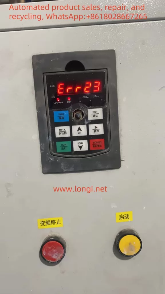
I. Introduction to Panel Functions and Initialization Settings of the LCGK-ZTV Inverter LC630 Series
1. Panel Function Introduction
The LC630 series inverters from LCGK-ZTV are equipped with an intuitive operation panel, which mainly includes a display screen, function keys, and status indicator lights. The display screen shows current working status, parameter settings, and other information; the function keys include “MENU” (menu), “ENTER” (confirm), “UP/DOWN” (selection), etc., used for parameter setting and navigation; the status indicator lights indicate power, operation, faults, and other statuses.

2. Initialization and Password Setting
Initializing the inverter typically involves restoring default parameter settings. The specific steps are as follows:
- Press the “MENU” key to enter the main menu.
- Use the “UP/DOWN” keys to select the “Initialization” option and press “ENTER” to confirm.
- The system will prompt whether to confirm initialization; press “ENTER” again to execute.
The LCGK-ZTV Inverter LC630 series supports password protection to prevent unauthorized modifications. The method for setting a password is as follows:
- After entering the main menu, select the “Parameter Protection” option.
- Use the “UP/DOWN” keys to select “Password Setting,” and press “ENTER” to enter.
- Input the desired password (typically a 4-digit number) and press “ENTER” to confirm.
- Input the password again for confirmation and press “ENTER” to save.
The method for clearing the password is similar. Simply select “Clear Password” after entering the current password in the “Password Setting” option and press “ENTER” to confirm.
3. Setting Panel Start and Panel Potentiometer Speed Adjustment
To achieve panel start and panel potentiometer speed adjustment, the following parameters need to be set:
- Pr033: Start source selection. Set to 0 for panel start; set to other values for external signal start.
- Pr034: Operating frequency source selection. Set to 0 for panel potentiometer speed adjustment; set to other values for external signal speed adjustment.
- Pr052: Enable PID function (set according to specific situations when used for constant pressure water supply control).
II. Method for Achieving Constant Pressure Water Supply Control
1. Introduction to PID Function
The PID control is key to achieving constant pressure water supply control with the inverter. By monitoring changes in water supply pressure, the PID controller automatically adjusts the output frequency of the inverter to maintain a constant water supply pressure.
2. Parameter Setting
According to the instruction manual for the LCGK-ZTV Inverter LC630 series (especially pages 58, 59, and 60), the following parameters need to be set to achieve constant pressure water supply control:
- Pr052: Enable PID function. Set to a non-zero value to enable PID control.
- Pr100: PID target value setting. Set the target value according to the required water supply pressure.
- Pr101: PID feedback signal source selection. Typically, select the output signal from the pressure sensor as the feedback signal.
- Pr102, Pr103, Pr104: Set the P (proportional), I (integral), and D (derivative) parameters of PID control, respectively. These parameters need to be adjusted according to the actual system response to achieve the best control effect.
- Pr105: PID output limiting. Set the maximum and minimum values of the PID output signal to prevent the inverter output frequency from exceeding the allowed range.
3. Notes
- When setting PID parameters, ensure system stability and quick response.
- Regularly check the accuracy of the pressure sensor and feedback signal to ensure the accuracy of PID control.
- Adjust PID parameters according to actual water supply demands and pump performance to achieve optimal energy-saving effects.

III. Troubleshooting for Err23
1. Fault Mechanism Analysis
The Err23 fault code typically indicates a short circuit between the inverter output and ground. This may be caused by insulation failure of the motor or motor cables. When a short circuit occurs between the inverter output and ground, an excessively large current is generated, triggering the protection mechanism and displaying the Err23 fault code.
2. Fault Handling Method
When handling the Err23 fault, first check the insulation of the cables and motor:
- Disconnect the inverter’s power supply to ensure safe operation.
- Use an insulation resistance tester to test the insulation of the cables and motor. Check the insulation resistance between each phase of the cable and ground, as well as the insulation resistance of the motor windings, to ensure they meet the requirements. If the insulation resistance value is too low, it indicates insulation failure.
- For cables, replace them with new ones that match the specifications of the original cables. During replacement, ensure the integrity and insulation performance of the cables to avoid new damage during wiring.
- For the motor, if the insulation failure is severe, the entire motor may need to be replaced. When replacing the motor, ensure that the specifications and performance of the new motor match those of the original motor to meet the operational requirements of the inverter.
- If the Err23 fault code persists after replacing the cables or motor, it may be necessary to consider replacing the entire unit. This typically indicates that there may be other faults within the inverter causing the ground short circuit issue.
