I. KCINT Inverter KC280/KC300 Series User Guide
1. Terminal Panel Start and Speed Regulation Method
The KCINT Inverter KC280/KC300 series can be started and speed-regulated through the terminal panel. Specific operations are as follows:

- Wiring Instructions:
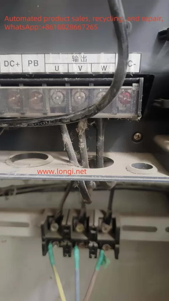
- Connect the three-phase power supply to the R, S, T terminals of the inverter.
- Connect the U, V, W terminals of the motor to the U, V, W output terminals of the inverter.
- Connect the ground wire to the PE terminal of the inverter.
- Parameter Settings:
- Set P0.01 to 0 to select the keyboard command channel.
- Set P0.03 to 0 to select the keyboard setting mode.
- Set P0.07 to the desired operating frequency.
- Operation Method:
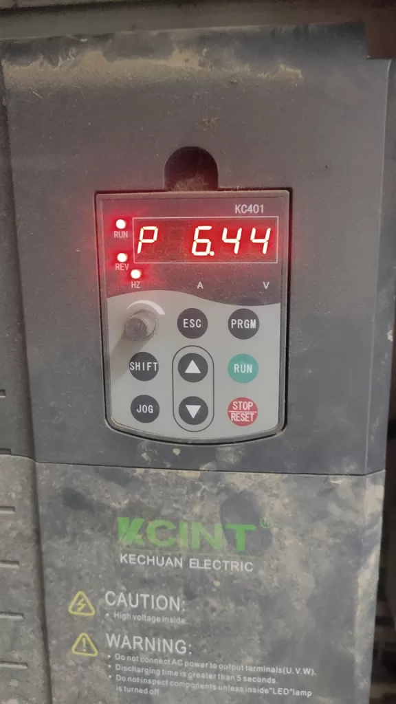
- Press the RUN button to start the inverter.
- Hold the ▲ button to increase the output frequency of the inverter; hold the ▼ button to decrease the output frequency.
- Press the STOP button to stop the inverter.

2. Terminal Forward/Reverse and External Potentiometer Speed Regulation Method
- Wiring Instructions:
- Connect the three-phase power supply to the R, S, T terminals of the inverter.
- Connect the U, V, W terminals of the motor to the U, V, W output terminals of the inverter.
- Connect the ground wire to the PE terminal of the inverter.
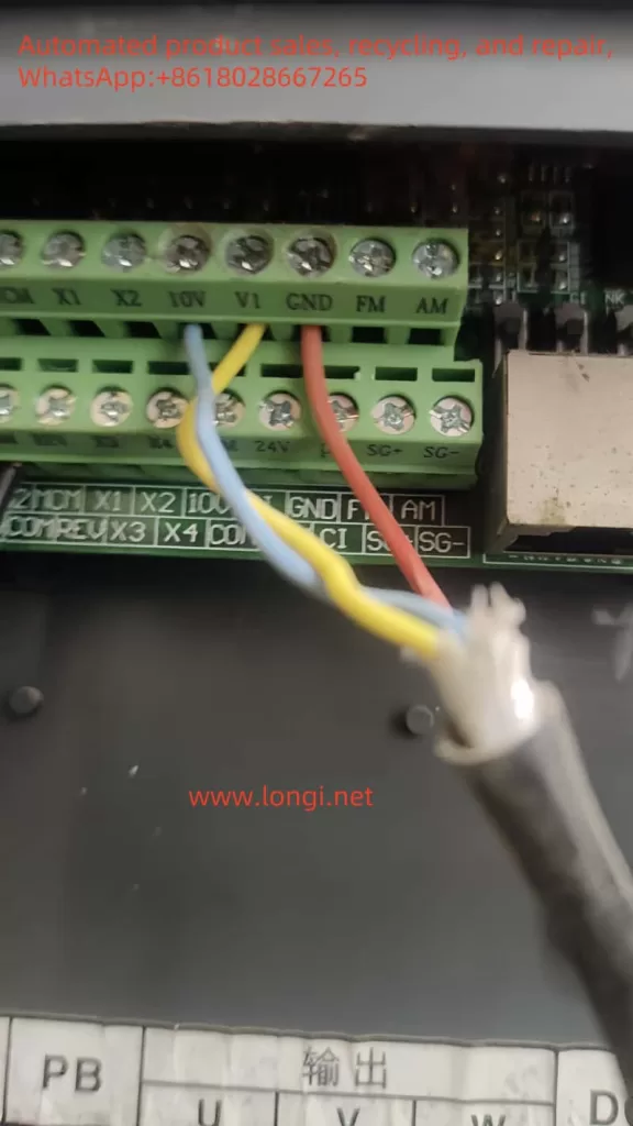
- Connect the output terminal of the external potentiometer to the VI terminal of the inverter, and the common terminal to the GND terminal.
- Connect the forward control terminal FWD-COM to the forward control signal, and the reverse control terminal REV-COM to the reverse control signal.
- Parameter Settings:
- Set P0.00 to 1 to select the input terminal control mode.
- Set P0.01 to 1 to select the terminal command channel.
- Set P0.03 to 1 to select the analog VI setting mode.
- Set P5.07 to 0 to select the two-wire control mode.
- Operation Method:
- When only FWD-COM is closed, the motor rotates forward; when only REV-COM is closed, the motor rotates reverse; when both are closed or open, the motor decelerates and stops.
- Adjust the external potentiometer to change the output frequency of the inverter, thereby achieving speed regulation.

II. Closed-Loop PID Control Application in Constant Pressure Water Supply
1. Parameter Settings
- Set P0.03 to 5 to select the PID control setting mode.
- Set P0.13 to 3 to select the constant pressure water supply macro function.
- Set P9.00 to 0 to select the keyboard preset PID setting.
- Set P9.01 to the desired PID setpoint (relative value, 0~100%).
- Set P9.02 to 0 to select the analog channel VI feedback.
- Adjust PID parameters such as P9.04 (proportional gain), P9.05 (integral time), and P9.06 (derivative time) as needed to achieve the desired control effect.
2. Wiring Instructions
- Connect the output terminal of the remote pressure gauge or 4-20mA pressure transmitter to the VI terminal of the inverter, and the common terminal to the GND terminal.
- Correctly connect the power wire and signal wire according to the wiring requirements of the pressure gauge or transmitter.
3. Operation Method
- After starting the inverter, adjust the PID setpoint (A value) through the panel’s up and down keys.
- The system will automatically adjust the output frequency of the inverter based on the set PID parameters and feedback signals to maintain a constant water supply pressure.

III. Fault Code Analysis and Solutions
The KCINT Inverter KC280/KC300 series may display various fault codes during operation. The following are some common fault codes, their analyses, and solutions:
- FL (Inverter Unit Fault):
- Possible Causes: Too fast acceleration, internal IGBT damage, interference causing malfunctions, poor grounding, etc.
- Solutions: Increase acceleration time, check and eliminate interference sources, check grounding, etc.
- OC (Overcurrent Fault):
- Possible Causes: Too fast acceleration or deceleration, large load inertia torque, low grid voltage, insufficient inverter power, etc.
- Solutions: Increase acceleration or deceleration time, select a larger inverter, check grid voltage, etc.
- OU (Overvoltage Fault):
- Possible Causes: Abnormal input voltage, too fast deceleration, large load inertia, etc.
- Solutions: Check the input power supply, increase the deceleration time, add suitable energy consumption braking components, etc.
- LU (Bus Undervoltage Fault):
- Possible Cause: Low grid voltage.
- Solution: Check the grid input power supply.
- OL (Overload Fault):
- Possible Causes: Low grid voltage, incorrect motor rated current setting, motor stall or excessive load mutation, etc.
- Solutions: Check the grid voltage, reset the motor rated current, check the load, etc.
When using the KCINT Inverter KC280/KC300 series, wiring and parameter settings should be strictly carried out according to the manual, and regular maintenance and servicing of the inverter should be performed to ensure its normal operation and extend its service life. At the same time, for fault codes that appear, the cause should be promptly analyzed and corresponding solutions taken to ensure the smooth progress of the production process.
