I. Introduction to Inverter Panel Functions and Basic Operations
1. Panel Function Introduction

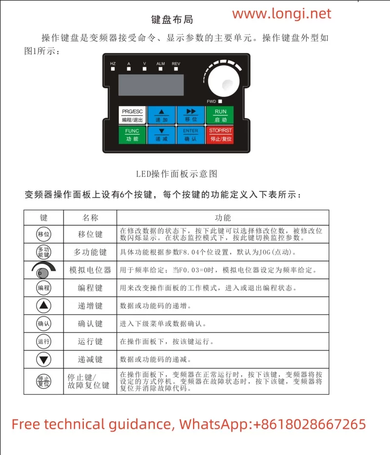
The RMSPD INVERTER SPD990M Mini is equipped with an LED operation panel that primarily includes the following function keys:
- Shift Key: Used to select digits for modification when editing data.
- Multi-function Key: Function set by parameter F8.04, defaulting to Jog.
- Analog Potentiometer: Used for frequency setting.
- Programming Key: Enters or exits the programming mode.
- Increment/Decrement Keys: Adjusts data or function codes.
- Confirm Key: Enters the next menu level or confirms data.
- Run Key: Starts the inverter.
- Stop/Reset Key: Stops the inverter or resets faults.
2. Resetting to Factory Defaults
To reset the inverter to its factory settings, follow these steps:
- Enter the programming mode (press the programming key).
- Use the shift and increment/decrement keys to select function code F8.03.
- Press the confirm key to enter F8.03 settings and select “1” for factory reset.
- Press the confirm key again to save and exit.
3. Starting, Stopping, and Adjusting Frequency via Panel
- Starting: Press the run key to start the inverter.
- Stopping: Press the stop key to stop the inverter.
- Frequency Adjustment: Use the analog potentiometer or increment/decrement keys to adjust the output frequency.
4. Terminal Forward/Reverse Control and External Potentiometer Frequency Setting
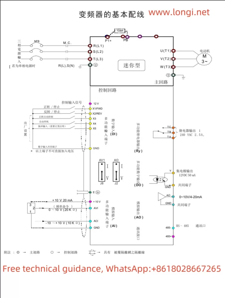
- Forward/Reverse Control: Control via terminals X1 (forward) and X2 (reverse), requiring F2.13 and F2.14 to be set to corresponding functions.
- External Potentiometer Frequency Setting: Connect to the AVI terminal and set F0.03 to 3 (AVI analog input).
II. PID Function Control for a Single Water Pump Motor
1. PID Function Wiring and Parameter Settings
- Wiring: Connect the PID feedback signal to the AVI or ACI terminal.
- Parameter Settings:
- F3.00: Enable PID regulation, selecting appropriate input and feedback channels.
- F3.01: Set the PID setpoint.
- F3.02: Adjust the feedback channel gain.
- F3.03 and F3.04: Set the proportional gain (P) and integral time (Ti).
2. Sleep Function Settings and Wake-up
- Sleep Settings:
- F3.10 and F3.11: Set sleep and wake-up threshold coefficients.
- F3.12 and F3.13: Set sleep and wake-up delay times.
- Wake-up: When the feedback value is less than the wake-up threshold, the inverter will automatically wake up.
III. Controlling the Inverter via a Weinview Touchscreen using Modbus Protocol
1. Inverter Settings
- Communication Parameters:
- F6.00: Set the device address.
- F6.01: Configure Modbus communication parameters (baud rate, data format, etc.).
- Control Commands:
- Use function code 06 to write control commands to address 2002H for inverter forward/reverse and stop control.
- Read and write frequencies to address 2001H.
2. Reading Alarm Values
- Use function code 03 to read alarm codes starting from address 2100H.

IV. Fault Code Meanings and Solutions
| Fault Code | Name | Possible Causes | Solutions |
|---|---|---|---|
| E0C1 | Overcurrent During Acceleration | Too short acceleration time, undersized inverter | Extend acceleration time, choose a larger inverter |
| E0C2 | Overcurrent During Deceleration | Too short deceleration time, undersized inverter | Extend deceleration time, choose a larger inverter |
| EHU1 | Overvoltage During Acceleration | Abnormal input voltage | Check the input power supply |
| ESC1 | Power Module Fault | Output short circuit, control board malfunction | Check motor wiring, contact the manufacturer for service |
| EOL1 | Inverter Overload | Improper V/F curve settings, heavy load | Adjust V/F curve, choose a larger inverter |
V. Conclusion
The Shanghai RMSPD INVERTER SPD990M Mini is a powerful and easy-to-use variable frequency drive. Basic start, stop, and frequency adjustment can be achieved through the panel. Terminal control enables forward/reverse operation and analog frequency adjustment. PID functionality allows for closed-loop control of water pump motors. Communication with an upper computer can be facilitated via the Modbus protocol. In the event of a fault, referring to the fault code table can quickly identify the issue and take appropriate measures. We hope this guide assists users in better utilizing and maintaining the SPD990M Inverter.
