Introduction
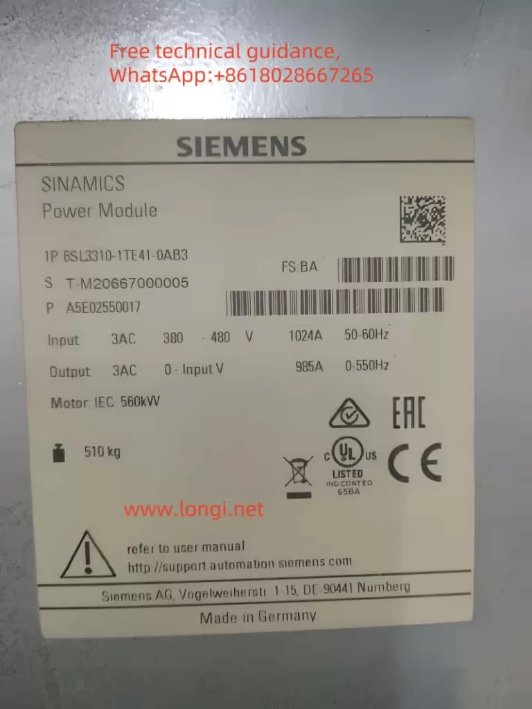
Siemens G130 and G150 series frequency converters play a crucial role in industrial automation systems, and their stability and reliability are vital for the smooth operation of production processes. However, in practical applications, these converters may encounter various faults, with F30005 (overload) and F30025 (overheating) being two of the most common ones. This article aims to provide an in-depth analysis of the meanings and causes of these faults and offer corresponding solutions. Additionally, a practical maintenance case is presented to illustrate the complexity of fault handling and the strategies employed.
Fault Analysis
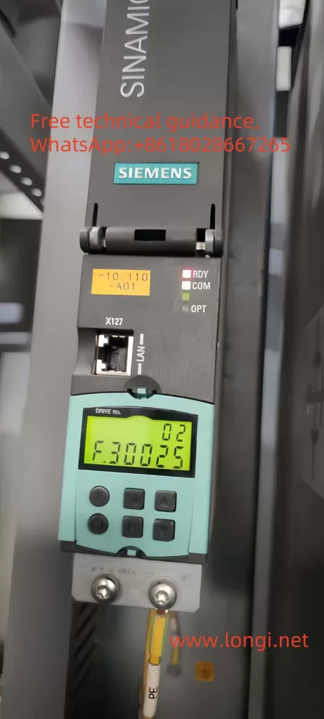
F30025 (Overheating)
The F30025 fault typically indicates that the power unit’s chip temperature is too high. This fault can be caused by various factors, including but not limited to:
- Poor Heat Dissipation: Issues such as fan failure, obstructed ventilation, or excessively high ambient temperatures can prevent the power unit from effectively dissipating heat.
- Overload Operation: Prolonged high-load operation generates significant heat within the power unit.
- High Pulse Frequency: Operating at high frequencies increases the heat generation in the power unit.
F30005 (Overload)
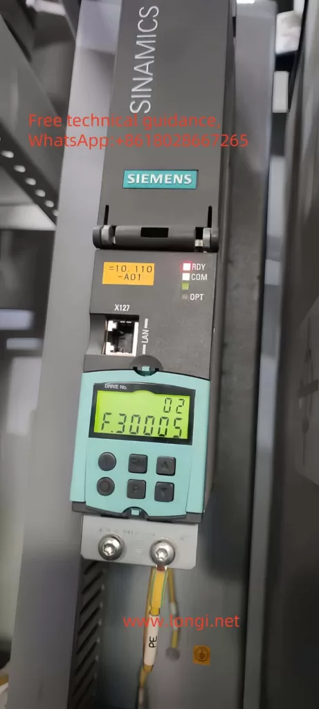
The F30005 fault signifies an I2t overload in the power unit. Possible causes include:
- Excessive Load: The motor or mechanical load exceeds the rated power of the frequency converter.
- Unreasonable Operating Cycle: Continuous operation without sufficient cooling time for the frequency converter.
- Improper Parameter Settings: Inappropriate settings for parameters such as acceleration and deceleration times, leading to excessive output current from the frequency converter.
Additionally, faults like overcurrent (F30001) and grounding (F30021) are also closely related to current detection and judgment, indicating output currents exceeding rated values and insulation damage to motors or cables, respectively.
Mechanisms of Fault Occurrence
Faults Occurring at Power-On
Faults that occur immediately upon power-on often point to hardware issues, such as damaged current sensors (transformers) or related detection circuit problems. These faults typically manifest as errors as soon as power is applied and are difficult to resolve through parameter adjustments.
Faults Occurring During Operation
Faults that arise during operation may be the result of a combination of factors, including load variations, ambient temperatures, and ventilation conditions. Such faults are usually addressed by optimizing parameters, reducing load rates, and improving ventilation conditions.
Solutions
Optimizing Parameter Adjustments
- Adjust Operating Cycles: Arrange the working and rest times of the frequency converter reasonably to avoid prolonged continuous operation.
- Adjust Acceleration/Deceleration Times: Modify acceleration and deceleration times based on load characteristics to reduce the impact on the frequency converter.
- Increase Preset Values for Electronic Thermal Protection: If the motor and frequency converter are not overloaded, the preset values for electronic thermal protection can be appropriately increased.
Reducing Load Rates
- Check and Optimize Mechanical Loads: Ensure that mechanical loads operate within the rated power range of the frequency converter.
- Adjust Gear Ratios: Where possible, adjust gear ratios to reduce the load on the motor axis.
Ensuring Adequate Ventilation
- Regularly Clean Heat Sinks: Ensure that heat sink fins are free of dust and that fans are operating normally.
- Improve Ventilation Conditions: Ensure that the frequency converter is installed in a well-ventilated location, away from direct sunlight and high-temperature environments.
Fault Repair
Handling Faulty Current Sensors
- Check Current Sensors: Use a multimeter to test the output of the current sensors for normality.
- Replace Damaged Current Sensors: If a sensor is confirmed to be damaged, it should be promptly replaced with a compatible model.
- Adopt Temporary Solutions: In emergencies, if only two current sensors are available, the frequency converter can be set to V/F control mode, but risks should be noted.
Repairing Drive Boards
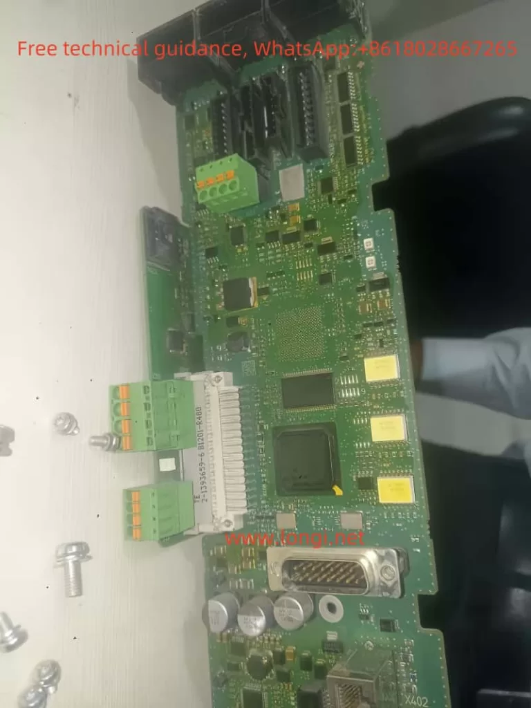
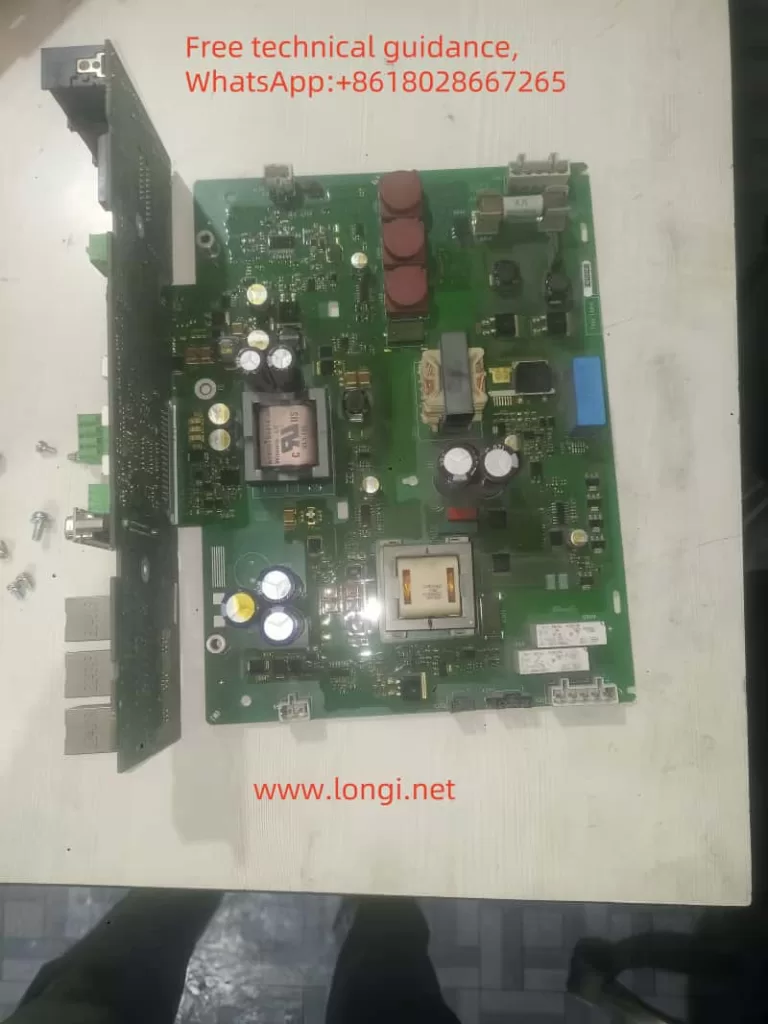
- Check Optocouplers on Drive Boards: Optocouplers are key components for detecting the voltage drop across switching transistors and should be replaced if damaged.
- Rewire or Replace Faulty Components: If other components (such as resistors, capacitors) on the drive board are damaged, they should be rewired or replaced.
Checking Current Detection Circuits
- Trace Current Signal Paths: From the current sensors to the frequency converter’s control circuit, gradually check each component along the signal path.
- Use Oscilloscopes to Detect Signal Waveforms: Observe the waveforms of current signals through an oscilloscope to identify any abnormalities.
- Repair or Replace Faulty Components: Based on the detection results, repair or replace faulty components.
Practical Maintenance Case
In actual maintenance, we encountered a typical case that fully demonstrated the complexity of concurrent F30005 and F30025 faults and their solutions. The frequency converter immediately displayed an F30025 fault upon power-on, and further operation (such as pressing the ↓ key) revealed an F30005 fault, indicating simultaneous issues of overheating and overload.
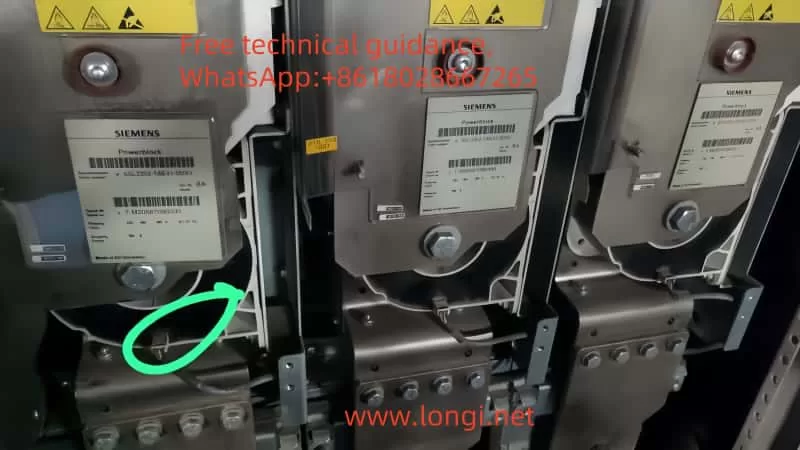
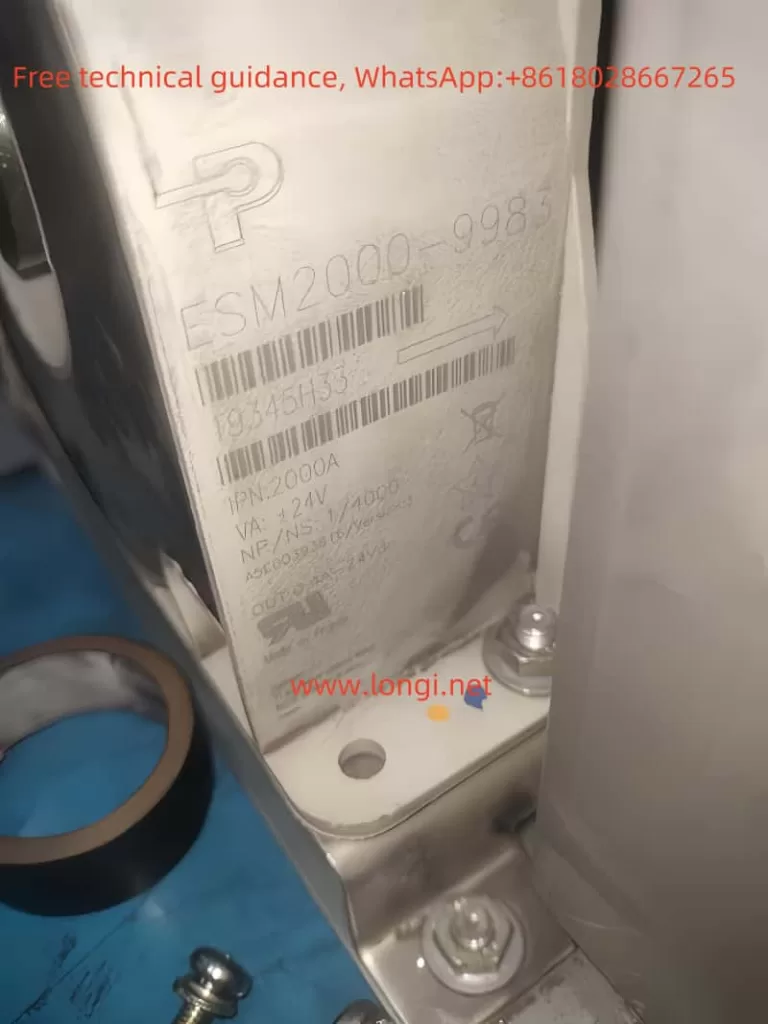
Upon thorough inspection, it was found that the root cause was a damaged current sensor. This frequency converter utilized three ESM2000-9922 current sensors, each with a maximum secondary side output current of 400mA, collectively responsible for monitoring the three-phase current output of the converter. According to Kirchhoff’s Current Law, the sum of currents entering a node at any moment should equal the sum of currents exiting the node. In a three-phase system, this means that the algebraic sum of any two phase currents must equal the negative of the third phase current. Therefore, theoretically, as long as two current sensors are functioning normally, the reading of the third sensor can be inferred from their data.
However, this substitution scheme carries risks in practical operation, requiring that the three-phase currents and voltages output by the frequency converter remain relatively balanced and that the angle between the currents is close to the ideal 120°. Furthermore, since this frequency converter supports vector control, precise current measurement is crucial. Therefore, when adopting this temporary substitution scheme, we had to switch the converter’s operating mode from vector control to V/F control to avoid damaging the IGBT module due to inaccurate current calculations.
During the specific operation, we removed the damaged current sensor and reconnected the remaining two sensors. Then, through the frequency converter’s parameter setting interface, we changed its operating mode to V/F control. After these steps, although the frequency converter could be started and operated, the current values displayed on the screen were slightly lower than the actual values. In emergencies, this makeshift solution can temporarily restore the functionality of the frequency converter and ensure the continuity of the production process. However, in the long run, we still recommend replacing the damaged current sensor as soon as possible and restoring the frequency converter to its original vector control mode to ensure its performance and accuracy.
Conclusion
Although F30005 and F30025 faults are common in Siemens G130 and G150 series frequency converters, they can be effectively prevented and resolved through reasonable parameter adjustments, load reduction, improved ventilation conditions, and prompt fault repairs. In practical applications, targeted measures should be taken based on specific situations to ensure the stable operation of the frequency converters. Meanwhile, through meticulous inspections and flexible strategies, we can identify the key to solving problems and ensure the long-term reliable operation of the equipment.
