
In the realm of industrial equipment maintenance, frequency converters play a crucial role in controlling motor speed and efficiency. Recently, I encountered two Delta VFD-A frequency converters that required extensive repairs due to severe damage in their output modules and driving circuits. This article documents the step-by-step process of diagnosing, repairing, and testing these converters, highlighting key lessons learned.
Initial Inspection and Diagnosis
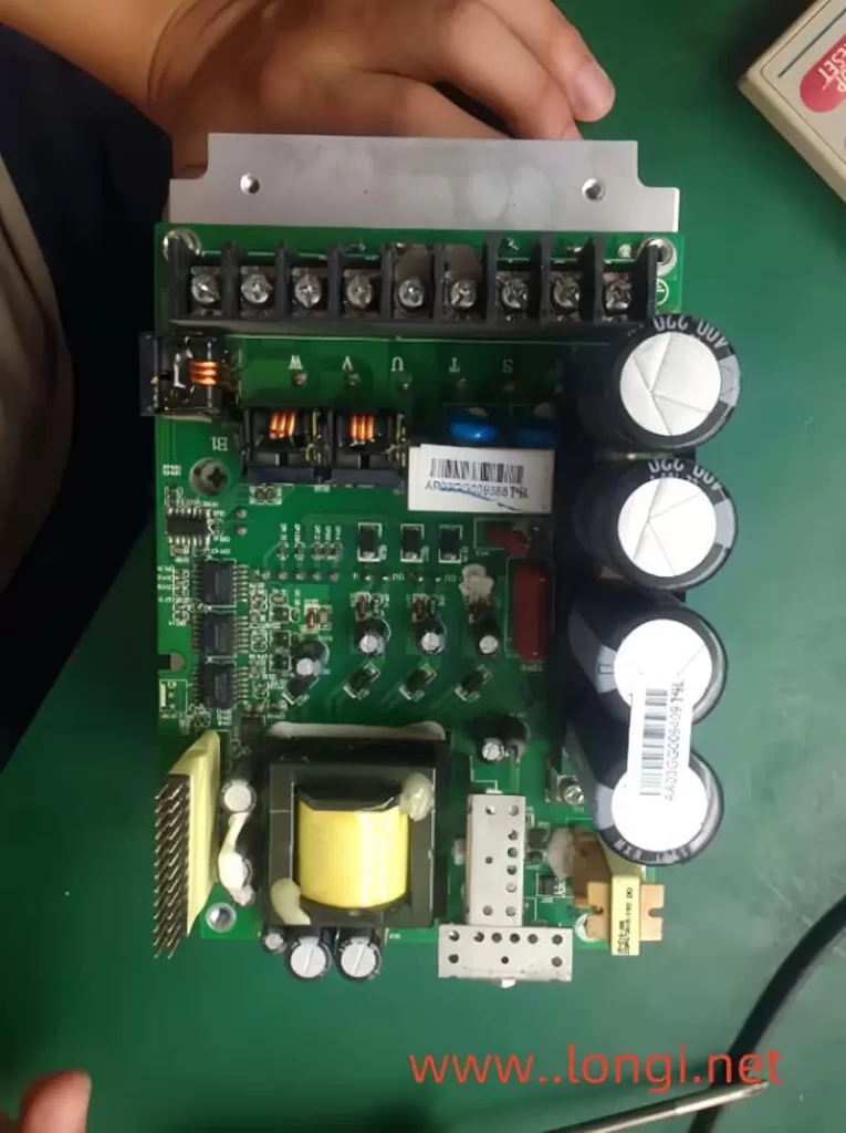
Upon receiving the two converters, a thorough inspection revealed significant damage: the output modules were compromised, and the driving circuits were in poor condition. Specifically, the T250V driving integrated circuits were either exploded or short-circuited to the power supply ground. Additionally, filtering capacitors had leaked, voltage regulator tubes were broken, resistors were open or had increased resistance, and the circuit boards were carbonized.
Further inspection of one converter revealed a broken arm in the three-phase rectifier bridge, along with a damaged charging current limiting resistor. The charging resistor was short-circuited, and the relay contacts were stuck, leading to severe damage. Several signal introduction resistors on the input side of the driving integrated circuit were also open, indicating that the CPU had likely suffered a strong electrical shock.
Circuit Analysis and Component Replacement
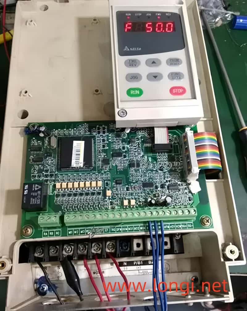
With the main circuit and driver circuit diagrams in hand, I began a comprehensive inspection. Using a small knife, I scraped off the carbonized parts of the circuit board and removed all damaged components. After ensuring there were no short circuits in the main circuit, I powered on the converter for a preliminary inspection. The display was normal, indicating that the switch power supply and control section were functioning.
An oscilloscope measurement of the six driver inputs (trigger signals from the CPU) revealed a peak voltage of 1.5V and a carrier frequency of 10kHz, which varied with frequency and pulse width. This confirmed that, apart from the damaged inverter and drive circuits, all other circuits were operational. The CPU’s three-phase pulse output terminal had withstood the electrical shock remarkably well.
I immediately procured the necessary replacement parts and began the repair process. Over 30 components in the driver circuit were replaced, and I tested the static DC voltage of each pin of the driver integrated circuit upon powering on. All measurements were within normal ranges. An oscilloscope was then used to measure the output waveforms of each integrated circuit, which were also within normal limits. With these repairs complete, I proceeded to weld the inverter output module.
Testing and Further Issues
Upon powering on the repaired converter for testing, I noticed a three-phase imbalance using a multimeter. Switching to the DC 500V range revealed no DC component between V and W, but there was DC voltage between U and V, as well as U and W. This indicated an issue with the U-phase output.
Further inspection revealed that the voltage regulator diode DD11 in the EU circuit’s triggered power supply was damaged. After replacing it with a regular component (the original SMD component had weak bonding), I accidentally desoldered it during the installation of the inverter module. This caused the triggering end of the upper transistor in the U-phase to be forced to a low level, resulting in only the negative half-wave output of the lower transistor being conductive.
I re-soldered DD11 and tested the machine again. The three-phase output was balanced, and there was no DC component. A 5.5kW submersible pump was connected for further testing, and both startup and operation were normal. The first frequency converter was successfully repaired.
Lessons Learned and Second Converter Repair
When repairing the second converter, I followed the same cleaning and repair steps as the first. However, after welding the inverter module and connecting three light bulbs for testing, I encountered a problem. Upon momentarily short-circuiting the control terminals DCM and FWD to initiate forward starting, I heard a “snap” sound – the newly replaced inverter output module had instantly exploded and damaged.
Upon investigation, I realized that I had forgotten to solder two output pulse introduction resistors on the back of the circuit board. This oversight caused the inverter module to be damaged due to the instantaneous and painless reverse output. It is crucial to thoroughly check all trigger terminal connections before conducting power tests to avoid such costly mistakes.
Mechanism of Damage
The damage to the inverter module was caused by short-circuit breakdown and explosion, resulting from overcurrent rather than overvoltage. Even when unloaded, the simultaneous conduction of two IGBT tubes in the inverter circuit can lead to a short circuit and subsequent module damage. This highlights the importance of ensuring that all trigger terminal leads are securely connected before powering on the converter.
Conclusion
Repairing these two Delta VFD-A frequency converters was a challenging but rewarding experience. It underscored the importance of thorough inspections, meticulous repairs, and rigorous testing. By documenting this process, I hope to provide valuable insights for others facing similar repair challenges in the future.