
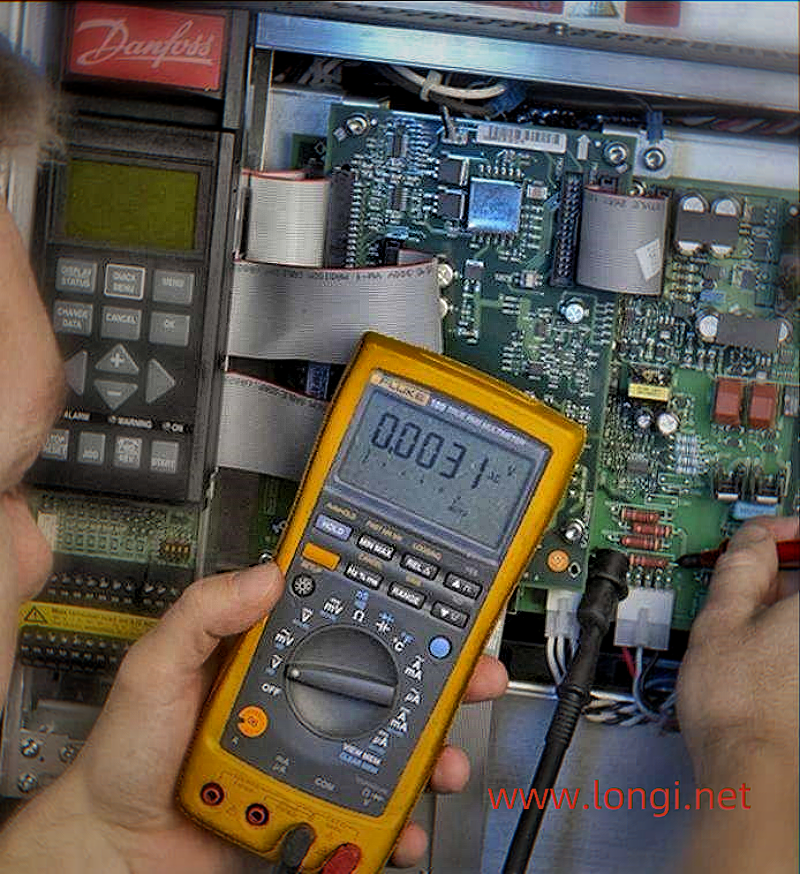
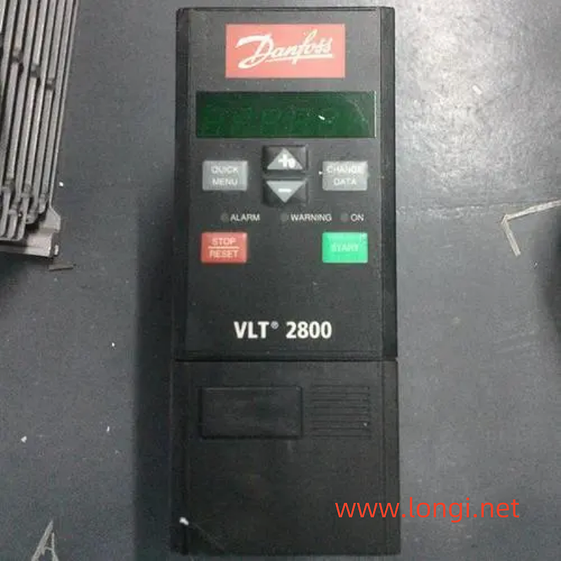
Danfoss Denmark produced two VLT2800 (2900) low-power (3kW) models, which tripped Err-7 during operation, meaning “overvoltage” and caused the frequency converter to shut down. Sometimes Err-5 is also triggered, with a high voltage warning. The measured three-phase power supply is 400V, which is within the rated range. Use the+key on the operation panel to call up the Ud (main circuit DC voltage) value. When it exceeds 600V, a trip and shutdown will occur.
According to the instructions: When the DC circuit of this model has an undervoltage below 370V, it will trip due to undervoltage; Low voltage warning given at 400V, but still operational; When it is not higher than 665V, a high voltage alarm is given, but it can still operate; When the voltage is higher than 665V -820V, the delayed tripping and shutdown can be described as having an extremely wide voltage protection range!
During the power on inspection, the Ud display value of a machine is unstable, which may be due to a change in resistance in the detection circuit. Diagnosed as abnormal Ud detection circuit. The Ud sampling circuit consists of 8 820k resistors and two 13k resistors connected in series, and their voltage division value is used as the Ud signal. Due to the urgent repair time required by the user, there was no time to thoroughly investigate the subsequent circuit. After connecting 8 820k resistor circuits with another 330k resistor in series, the machine was powered on and tested. When the input three-phase AC voltage was 440V (supplied by the regulator), Err-7 was no longer triggered, so the user took away the installation.
User installation, trial operation, one unit jumps Err-8, undervoltage; One device jumps Err-37 and has poor communication.
Determine if the Ud detection circuit is still faulty. Following the principle of prioritizing ease over difficulty, we will still focus on these 10 resistor detection circuits. Reserve three 820k resistors from the P+end of the power supply, connect a 6V voltage regulator in series and then connect the N end. Connect the 6V voltage regulator in series with a 1M or 100k semi variable resistor. Disassemble one 13k resistor at the signal input end and connect the center end of the variable resistor as the Ud signal. Calculate the Ud sampling voltage. When the input is 380V, it is approximately 2.2V. Adjust the semi variable resistor to output 2.2V at the center end, and define this voltage as U-sampling.
The process of power transmission and debugging is very interesting: when the U voltage is greater than 2.2V, Err-37 jumps when powered on, which means there is a communication failure between the control card and BMC. However, the essence of this phenomenon is that it is not because the communication between the control card and BMC is interrupted that Err-37 jumps, but because the control circuit detects that Ud is really “frighteningly high”, it forcibly interrupts the communication between the control card and BMC, and then jumps Err-37 to give a warning! When the U voltage approaches 2.2V, pressing the reset button can eliminate the Err-37 alarm, and FT-00 will appear on the screen, entering standby mode; When the U voltage is less than 2.2V, the Err-35 will jump when powered on, indicating a startup impulse fault: if the frequency converter repeatedly connects the power supply within one minute, an alarm will be generated. But the essence of this phenomenon is that because the CPU detects that Ud is surprisingly low, it is treated as a low Ud formed by repeatedly starting the frequency converter in a short period of time, and an Err-35 alarm signal is given! When the U voltage is less than 2.2V, the capacitor charging short-circuit contactor is also in the released state. Only when the U voltage is close to 2.2V (i.e. Ud is higher than 400V), this contactor will be energized and the frequency converter will be allowed to enter standby mode.
When FT-00 appears on the screen, press the+key to adjust the Ud value, adjust the variable resistor by half, and make it display 500V stably. At this point, when inputting 220V-460V, the displayed value remains stable at 500V. After installation, it has been running normally.
It should be noted that this can only be used as one of the emergency repair methods, and it is indeed an overvoltage false alarm. Assuming that the undervoltage alarm is caused by the loss of capacity of the DC energy storage capacitor in the main circuit, the cause of the fault must be identified, and the fault must be effectively eradicated before repairing the U-sampling circuit!
Additionally, some models have output voltage that depends on the sampling voltage of the DC circuit, i.e. the output voltage tracks the three-phase input voltage. After such processing, the output V/F ratio will change. But generally it will not affect the use; For vector frequency converters, the DC voltage sampling value affects the control of the output three-phase voltage and current, so the sampling voltage cannot be easily changed!