I. Operation Panel Functions and Basic Settings
1. Operation Panel Function Introduction

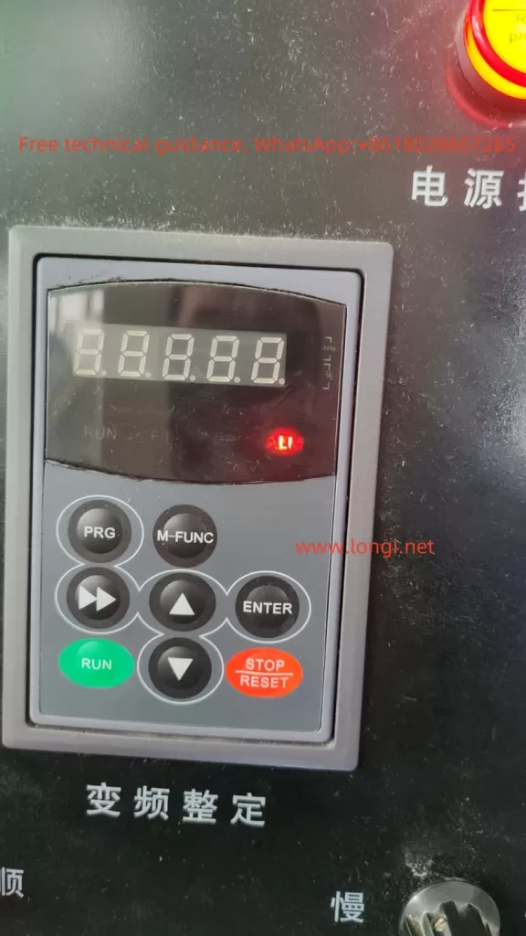
The EASYDRIVE M200 inverter’s operation panel features a straightforward design, incorporating keys such as RUN, M-FUNC (multifunctional), STOP/RESET, PRG (program switch), ENTER, ▲/▼ (data modification), and ▼▼ (data bit switch). The LED display can show set frequency, output voltage, output current, and other parameters.
2. Restoring Factory Defaults
To restore the EASYDRIVE M200 inverter to its factory settings, you can follow these steps via the operation panel:
- Enter the parameter setting interface (PRG key).
- Locate the F0-01 parameter (Parameter Initialization).
- Set F0-01 to 1 and press ENTER to confirm.
- The inverter will automatically restart and revert to factory settings.
3. Password Setting and Removal

To protect the inverter settings, a user password can be set. The specific operations are as follows:
- Enter the parameter setting interface.
- Locate the F0-00 parameter (User Password).
- Set a non-zero digit as the password and press ENTER to confirm.
- To remove the password, set F0-00 to 0000.
4. Torque Boost, Cutoff Frequency, and Slip Frequency Compensation Settings
- Torque Boost Setting:
- Enter the F1 parameter group and find F1-13 (Torque Boost).
- Set the torque boost percentage (0.0% to 30.0%) according to the load condition.
- Cutoff Frequency Setting:
- Locate F1-14 (Torque Boost Cutoff Frequency).
- Set the cutoff frequency percentage (0.0% to 50.0%).
- Slip Frequency Compensation Setting:
- Enter the F1 parameter group and find F1-15 (V/F Slip Frequency Compensation).
- Set the slip frequency compensation percentage (0.0% to 200.0%).

II. Three-Wire Operation Control and External Potentiometer Settings
1. Three-Wire Operation Control
Three-wire operation control allows for forward, reverse, and stop control of the inverter through three terminals. The setup steps are as follows:
- Enter the F6 parameter group and find F6-09 (FWD/REV Terminal Control Mode).
- Set F6-09 to 2 or 3 to select the three-wire control mode.
- When wiring, connect the forward control terminal (e.g., DI1), reverse control terminal (e.g., DI2), and stop control terminal (e.g., DI3) to the corresponding function terminals, respectively.
2. External Potentiometer for Forward/Reverse and Speed Adjustment
An external potentiometer can be used for frequency setting on the inverter, enabling forward/reverse control and speed adjustment. The specific settings are as follows:
- Forward/Reverse Setting:
- Enter the F1 parameter group and set F1-02 (Main Frequency Source A Selection) to AI1 or AI2.
- When wiring, connect the center tap of the external potentiometer to the common terminal of the inverter (e.g., GND), and the other ends to AI1 or AI2 terminals, respectively.
- Adjust the potentiometer resistance to achieve forward or reverse rotation.
- Speed Adjustment Setting:
- Enter the F5 parameter group to set the input range of AI1 or AI2 (F5-00 to F5-03 or F5-05 to F5-08).
- Wiring is the same as above; adjusting the potentiometer resistance will change the output frequency.
III. Fault Diagnosis and Handling
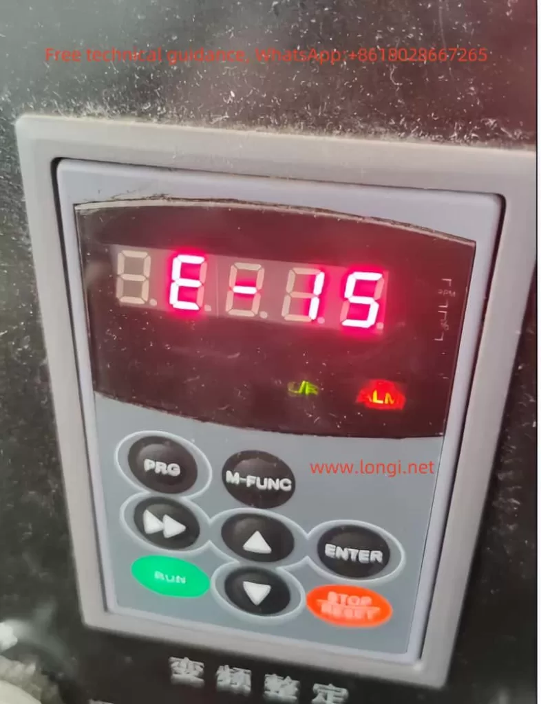
1. E-015 Fault (External Device Fault)
When the inverter displays the E-015 fault code, it indicates that the external device fault input terminal is closed. The solution is as follows:
- Check if the external device is functioning normally.
- Disconnect the external device fault input terminal and clear the fault.
2. Other Common Faults and Solutions
- E-01 Overcurrent During Acceleration:
- Possible Causes: Too short acceleration time, excessive load inertia.
- Solution: Extend the acceleration time, reduce the load inertia.
- E-02 Overcurrent During Deceleration:
- Possible Causes: Too short deceleration time, large inertial load.
- Solution: Extend the deceleration time, reduce the load inertia.
- E-07 Bus Undervoltage:
- Possible Cause: Abnormal input voltage.
- Solution: Check if the power supply voltage is normal.
- E-16 RS485 Communication Fault:
- Possible Causes: Improper baud rate setting, serial port communication error.
- Solution: Set the baud rate appropriately, check the communication cable and ensure the upper computer is working normally.
IV. Conclusion
The EASYDRIVE Inverter M200 User Manual provides a comprehensive operation guide, covering operation panel function introduction, basic settings, terminal control, external potentiometer settings, fault diagnosis, and handling. By reasonably setting parameters and correctly wiring, users can easily achieve various functions of the inverter, ensuring stable equipment operation. Meanwhile, understanding common faults and solutions helps users quickly locate and troubleshoot issues, improving equipment efficiency and reliability.
