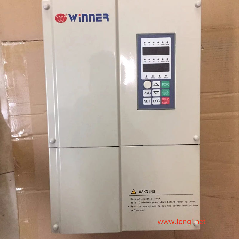
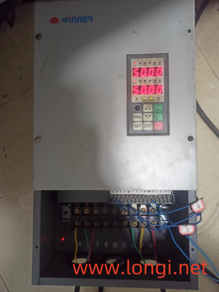
Cause: A cement plant user sent a 75kW micro energy WIN-G9 frequency converter for repair. The cause of the malfunction was that during operation, the frequency converter suddenly caught fire and emitted smoke, causing it to shut down. Upon inspection, the power input circuit of the machine is a three-phase half controlled bridge. Using its controllable rectification principle, the DC main circuit energy storage capacitor is “soft charged”, eliminating the commonly used charging contactor for low-power frequency converters. In fact, the semi controlled bridge here is equivalent to a contactless soft switch. Upon inspection, it was found that there were obvious signs of arc flashover and burning on the terminals of one of the thyristor modules, but the measurement did not indicate a short circuit. During disassembly, it was found that the fixing nut was easily removed, and the cause of the flashover seems to be due to loose connection screws, causing poor contact. This module is a combination of a diode and a unidirectional thyristor. Further check the control board and inverter main circuit, and there are no abnormalities. After removing the module, the remaining two phase half control bridges were used as power inputs. After being powered on, a 2.2kW low-power three-phase motor was tested and there were no issues. After replacing it with a new module of the same model, it was installed on site.

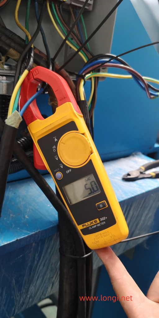
To be cautious, first adjust the operating frequency to 5Hz, and the frequency converter is loaded with a fan. First, disconnect the motor connector and let the motor run at no load. This trial run was a shock! When the frequency is below 5Hz, the no-load operating current is 45A. Although it feels slightly higher, it may be caused by the repair of the motor winding or the adjustment of the parameters of the frequency converter, such as the starting curve or torque compensation, which was not taken into consideration. When the speed was increased to 10Hz, both the current displayed on the frequency converter panel and the output current measured with a clamp meter reached 100A! And the oscillation amplitude of the output current is very large, but when measuring the three-phase output voltage, it is about 70V, balanced and stable. Disconnect the motor connection wire and power on to measure the output of the frequency converter. The output voltage is 70V at 10Hz, 150V at 20Hz, and 250V at 35Hz. As the operating frequency increases, it reaches 400V at 50Hz. During this process, the balance of measuring the three-phase output voltage is very good. The V/F curve output by the frequency converter conforms to the quadratic load torque characteristics. No problem. The output voltage is balanced and stable, while excessive output current and severe current fluctuations are clearly caused by abnormal loads. This is a conclusion drawn from conventional judgment.
Discuss with the relevant technical personnel of the factory, attempting to identify the reasons for the motor and mechanical aspects. For example, whether the motor is newly repaired or whether the winding is poorly wound; Check for wear and unstable operation of bearings; Is there any looseness or non concentricity in the connecting shaft; The wind blades have deformation, etc. Restore the wiring of the original power frequency starting cabinet, compare the power frequency starting motors, and eliminate the above doubts one by one. According to on-site observations, the motor and connected loads are in good condition, and there is almost no electrical and mechanical noise during operation. The no-load current under full speed operation is only less than 35A, with three-phase balance and no fluctuation! There is no problem with the motor and load, and the problem is still with the frequency converter.
So where is the fault location of the frequency converter? It’s a bit scratching my head. Is the current detection inaccurate, causing erroneous output? The current value displayed on the observation panel is close to the value measured by the clamp ammeter, and there should be no problem. Is there still a problem with the CPU motherboard and the output driver waveform incorrect? It doesn’t make sense. All digital circuits, why is the waveform incorrect?
Fortunately, there is another inverter of the same model and power not far from here on site, carrying the same load. That’s great. This has brought great convenience to comparative experiments. The factory was eager to start the machine and provided active cooperation. Swapping the current transformers of two frequency converters is ineffective; Swapping the CPU motherboards of two machines is invalid. Retrieve the DC voltage display of the main circuit, which is 550V, and there is no problem with the voltage sampling circuit. I can no longer figure out which circuit the problem lies in. When the comparison machine is under load, the operating current is 75A at 10Hz. When it reaches 35Hz or above, the operating current only reaches 100A, which is smaller than the current of this motor with no load. The no-load current is much higher than the load current, so there must be a problem with the frequency converter.

During the trial operation, I occasionally measured the three-phase output current of the inverter using a current clamp meter, and even discovered an incredible phenomenon! The input and output currents of this frequency converter are completely disproportionate, with a difference of more than 10 times!
When outputting a 40A current, the input current is a few amperes, which is almost undetectable; When outputting 100A current, the input current is only below 8A! Strange, it doesn’t comply with the law of conservation of energy. Where did the 100A output current come from?! It’s like an airtight water pipe, where 1 cubic meter of water enters and 10 cubic meters of water flows out. The water inside the pipe cannot come out.
We all know that in general, the input current of the frequency converter is always smaller than the output current. The reason is that the energy storage capacitor in the DC circuit acts as if a reactive power compensation cabinet is installed at the motor end. When the frequency converter is unloaded or lightly loaded, a portion of the current is provided by the energy storage capacitor to the load, reducing the current absorbed by the frequency converter from the grid. As the load increases, the input current of the frequency converter increases proportionally. When the rated load is applied, the input current and output current of the frequency converter should be close to equal. When outputting 40A, the input is only a few amperes; When outputting 100A, the input current has reached 70A; When the output current reaches 140A, the input current has also reached this value. Under normal circumstances, there may be a difference in input and output currents, but there will not be an extremely significant difference as mentioned above. The huge difference made me doubt whether the measuring instrument was broken. After changing the watch and retesting, the same result was still obtained.
There’s no way out. Consult the manufacturer. Due to the urgent need to solve the problem and find the answer, it’s not worth considering whether long-distance phone calls are expensive at this time. The technical personnel from the frequency converter manufacturer replied that this model of frequency converter is the earliest produced frequency converter, and there are problems with slightly higher no-load current and current fluctuations, but it is a normal phenomenon and does not affect its use. After being loaded, the current will stabilize. It is best to connect a motor of the same power for testing to see if there is a problem with the motor or load. Problems with motor bearings. If all motor and load issues are eliminated, as long as the three-phase voltage output of the frequency converter is balanced and the output current does not exceed the rated current of the frequency converter, can the machine be tested under no load or on load. Can’t it break down. As for the proportion of input and output currents, it is difficult to have a fixed proportion due to different load conditions. It’s not proportional. Don’t get entangled with the issue of proportion.
Think about it too. As long as the output three-phase voltage is balanced and does not exceed the rated current, can the load test be conducted. Can’t the frequency converter break down. Perhaps after being loaded, there will be no significant fluctuations in the output current. Maybe it’s normal.
We had to conduct a load test and a miracle occurred (which was surprising): when operating at 10 Hz and outputting a current of 40A, the output current was only 7 out of 8 amperes. When operating at 30 Hz, the output current is 60A and the input current is 25A; When operating at 40 Hz, when outputting a current of 100A, the input current is 70 amperes. The operating current has decreased and the fluctuation has decreased, and it is basically stable. The three-phase voltage and three-phase current are both balanced and relatively stable. The problem was inexplicably solved.
Thank you to the manufacturer’s technical personnel for their guidance: why not try the machine on load. But due to encountering this situation for the first time, abnormal current occurs at no load, and it is not dare to increase to full speed for operation. I’m even more afraid to carry it. I always want to find out the reason before loading. I always thought this was an abnormality with the frequency converter.
After the frequency converter was put into operation and returned from the site, I am still pondering this issue.
Remembering the problem of high zero line current in a power plant during maintenance, caused by harmonic components in the transmission line. It’s harmonic current. Is there also a significant harmonic component in the output circuit of the frequency converter during no-load or light load operation? Where does this harmonic component come from? Is the measured result true?

The analysis shows that there are significant harmonic components in the output current during no-load operation. There may be two reasons for the high harmonic current: 1. The output PWM wave of the inverter is not ideal enough, and the modulation method is not optimal. The software control concept has not been optimized (the new machine must have been improved); 2. When unloaded, it is equivalent to a serious mismatch between the power supply capacity and the load capacity. The power supply capacity is much larger than the frequency converter capacity, which is also a major reason for the generation of harmonic currents. When running on load, the capacity matching situation improves, and the harmonic components are greatly reduced. The combination of these two reasons has stumped me, an old electrician. For me, during the test drive, I made an empirical mistake. I was bound by the ratio of input and output currents and almost surrendered.
