The RENLE Inverter NL100 series is a powerful and easy-to-operate frequency converter widely used in various industrial fields. This article will introduce in detail the functions of its operation panel, the setting of speed tracking functions, parameter initialization, password setting and removal, terminal forward and reverse control, external potentiometer speed regulation, as well as the meaning and solution of fault codes.

I. Introduction to Operation Panel Functions
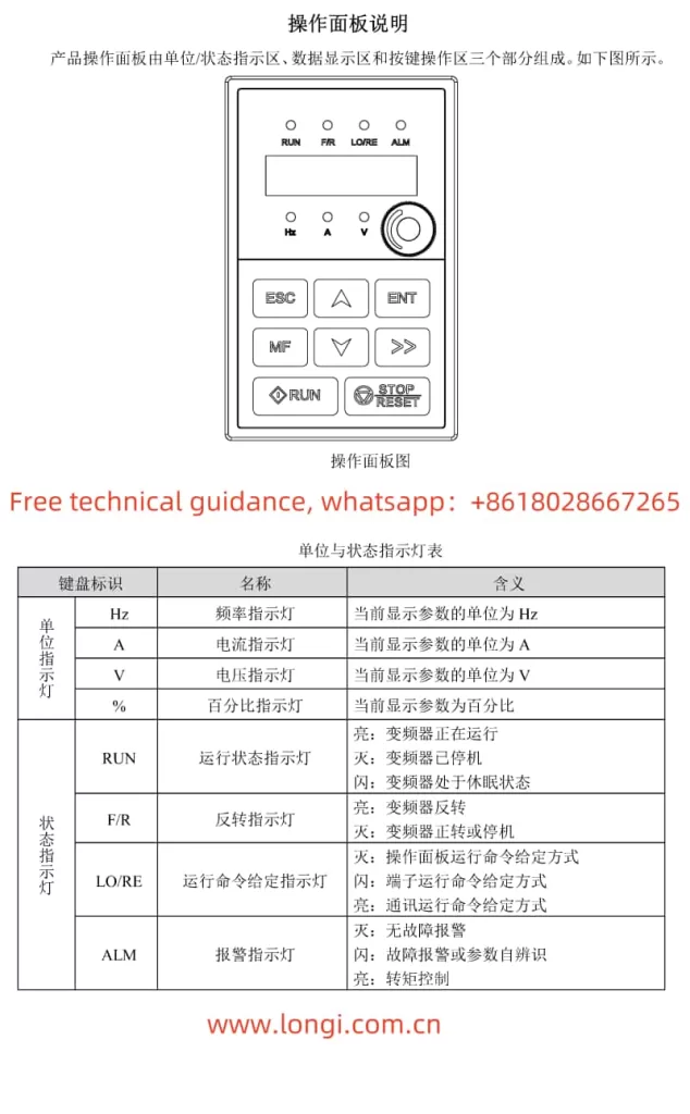
The operation panel is the core control component of the RENLE Inverter NL100 series, providing an intuitive operation interface and rich information display functions. The panel mainly consists of three parts: unit and status indicators, digital display area, and key operation area.
- Unit and Status Indicators: Used to display the current operating status of the inverter, such as the running status indicator (RUN), reverse indicator (F/R), running command given indicator (LO/RE), and alarm indicator (ALM).
- Digital Display Area: A 5-digit LED digital tube is used to display various monitoring data such as set frequency, output frequency, bus voltage, output current, and alarm codes.
- Key Operation Area: Includes programming/exit keys, multi-function keys, run keys, confirmation keys, shift keys, stop/reset keys, and increment/decrement keys, which are used for parameter setting, operation control, fault reset, and other operations.
II. Speed Tracking Function Setting and Parameter Initialization
Speed Tracking Function Setting:
The speed tracking function allows the inverter to start running from a set frequency after stopping instead of from 0Hz. The relevant parameter settings are as follows:
- F02.20 Speed Tracking Mode: Sets the starting point for speed tracking, with options including starting from the stopping frequency, starting from the power frequency, and starting from the maximum frequency.
- F02.21 Speed Tracking Speed: Sets the speed of speed tracking, with a higher value resulting in faster tracking.
- F02.22 Speed Tracking KP and F02.23 Speed Tracking KI: Set the proportional gain and integral gain of speed tracking respectively, used to adjust the accuracy and stability of tracking.
Parameter Initialization:
Parameter initialization can restore all parameters of the inverter to the factory settings. The specific operation steps are as follows:
- Press the programming/exit key to enter the parameter setting mode.
- Use the shift key and increment/decrement keys to select function code F05.01.
- Press the confirmation key to enter the parameter modification mode.
- Use the shift key and increment/decrement keys to set the parameter value to “01”.
- Press the confirmation key to save the settings and exit the parameter modification mode.
- The inverter will automatically perform parameter initialization and restart.
III. Password Setting and Removal, Terminal Forward and Reverse Control, and External Potentiometer Speed Regulation
Password Setting and Removal:
The password protection function can prevent unauthorized parameter modifications. The steps to set the password are as follows:
- Enter the parameter setting mode and select function code F05.03.
- Enter the parameter modification mode and set the desired password value (0~65535).
- Save the settings and exit the parameter modification mode. The password will take effect after 1 minute.
To remove the password protection, simply set the parameter value of F05.03 to 0.

Terminal Forward and Reverse Control and External Potentiometer Speed Regulation:
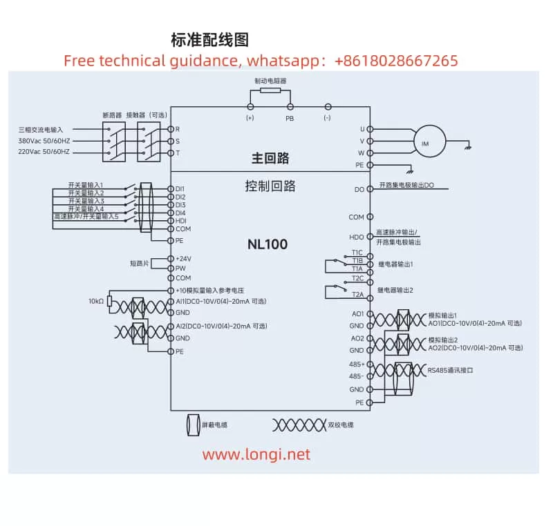
To achieve terminal forward and reverse control and external potentiometer speed regulation, the following parameters need to be set and wired correctly:
- F00.01 Command Source Selection: Set to “1” to select the terminal command channel.
- F06.00~F06.03 DI Terminal Function Selection: Set DI1 to forward operation (FWD) and DI2 to reverse operation (REV).
- F00.02 Main Frequency Source X Selection: Set to “4” to select the panel potentiometer AI0 as the main frequency source. If an external potentiometer is used, it needs to be connected to the AI1 or AI2 terminal, and F00.02 should be set to the corresponding value.
- Wiring: Connect the forward button to the DI1 and COM terminals, and the reverse button to the DI2 and COM terminals. The three terminals of the external potentiometer are connected to the AI terminal (such as AI1), GND terminal, and +10V terminal (if the potentiometer requires +10V power supply).
Forward and Reverse Dead Time Setting:
The forward and reverse dead time is used to prevent damage to the inverter or motor due to frequent actions during forward and reverse switching. The relevant parameter is F02.11, with a setting range of 0.0s~3000.0s. Adjust the parameter value according to actual application requirements.
IV. Fault Code Meaning Analysis and Solution
The RENLE Inverter NL100 series has a complete fault protection function. When a fault occurs, the inverter will display the corresponding fault code. The following are the meanings and solutions of some common fault codes:
- E.oC1 Overcurrent During Acceleration: Possible causes include too fast acceleration, low grid voltage, or insufficient inverter power. Solutions include increasing the acceleration time, checking the input power supply, or selecting an inverter with a larger power rating.
- E.oU1 Overvoltage During Acceleration: Possible causes include abnormal input voltage or restarting a rotating motor after a power outage. Solutions include checking the input power supply or avoiding restart after stopping.
- E.oL1 Motor Overload: Possible causes include low grid voltage, incorrect setting of motor rated current, or motor stall. Solutions include checking the grid voltage, resetting the motor rated current, or checking the load condition.
- E.oH1 Rectifier Module Overheat: Possible causes include instantaneous overcurrent of the inverter, output three-phase phase-to-phase or ground short circuit, etc. Solutions include referring to overcurrent countermeasures, rewiring, or ventilating the channel.
When a fault occurs in the inverter, first search for possible fault causes based on the displayed fault code and follow the corresponding solution. If the problem cannot be solved, please contact RENLE after-sales service for professional help.
Through the introduction of this article, I believe you have a deeper understanding of the operation guide of the RENLE Inverter NL100 series. In practical applications, please be sure to follow the instructions in the manual to ensure the normal operation and long-term stability of the inverter.
