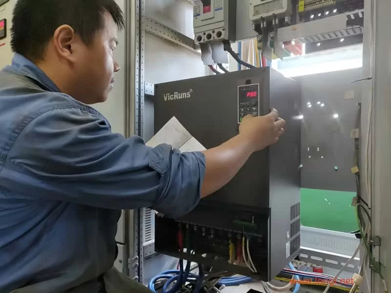
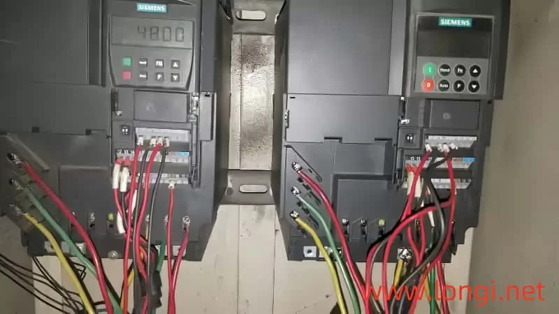
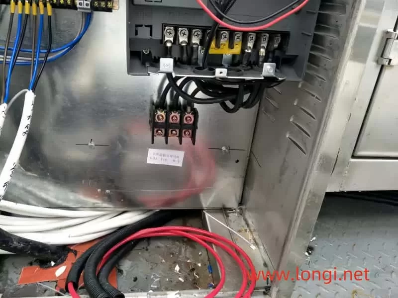
Variable Frequency Drives (VFDs), also known as frequency converters, are essential devices in modern industrial and commercial applications, providing precise control over motor speed and torque. However, their effective utilization requires a thorough understanding of their operational nuances and precautions. This article delves into the critical aspects of selecting and using VFDs to ensure optimal performance and longevity.

Operational Modes and Control Mechanisms
When integrating a VFD into your system, it’s crucial to understand its operational mode. Some VFDs cannot be directly controlled via the panel for start/stop operations. Instead, they require control terminals to be connected in either the forward or reverse direction. Essentially, the motor’s direction must be predetermined through these terminals before the panel can control the start/stop functions. This setup ensures seamless operational control and prevents any potential misdirections or malfunctions.
For applications involving pole-changing motors, it’s advisable to connect the VFD according to the high-speed connection method initially and then adjust the speed as required. If the motor needs to operate at lower speeds, a medium-speed connection can also be utilized. This flexibility allows for optimized performance across various speed ranges.
Voltage and Connection Considerations
Low-power motors with three-phase angle connections of 220V can be connected in a star configuration when using a VFD. This setup enables direct driving by a 380V VFD, maintaining the motor’s output power without the need to reduce the VFD’s output voltage. This approach is superior in terms of efficiency and performance.
In scenarios where the power supply capacity significantly exceeds the VFD’s capacity, harmonic components in the input current may increase. This can lead to increased losses and potential damage to rectifier diodes and capacitors. To mitigate these effects, installing input reactors is recommended. These devices improve the power factor, reduce the impact of three-phase current imbalance, and provide a degree of lightning protection.

Enhancing Performance and Reducing Interference
Installing an output reactor can further enhance the system’s performance by improving the current waveform, reducing motor operating noise, and boosting energy-saving effects. In cases where VFD-generated interference affects on-site instruments, lowering the carrier frequency can often resolve or mitigate the issue. For high-power motors, a moderate reduction in carrier frequency is advisable, particularly when starting difficulties arise. Adjusting the starting curve by shortening it and reducing the carrier frequency can facilitate smoother starts.
Motors with high operating inertia and specific stopping time requirements may need the addition of braking units and braking resistors. Proper adjustment of these parameters ensures smooth deceleration and stopping. When driving submersible pump motors, selecting a VFD with a higher power rating is recommended due to their larger rated current compared to ordinary motors.
Shutdown Methods and Torque Boosting
In constant pressure water supply systems using a single VFD, a deceleration shutdown method, akin to soft shutdown, can prevent the water hammer effect. However, in systems with one-to-several configurations or power frequency bypasses, a free shutdown method is preferable to avoid contactor tripping and potential damage to the VFD module from the motor’s back electromotive force.
Torque boosting parameters must be carefully set and tested. Excessive torque boosting at low frequencies can cause motor windings to become overexcited, leading to magnetic saturation and a significant torque reduction. This can result in the motor emitting a buzzing sound without rotating, accompanied by a substantial increase in output current, potentially triggering OC faults. Reducing the torque boosting parameter often resolves this issue.

Parameter Protection and Maintenance
If parameters cannot be modified, it may indicate that they are protected or restricted. In such cases, adjusting relevant parameters to disable protection or performing parameter initialization can be necessary. In dusty environments, regular cleaning and dust prevention measures are crucial to maintain VFD performance.
When wiring low-power VFDs (below 1kW), it’s vital to check the voltage level label on the nameplate to ensure correct connection. Misconnecting a 220V VFD to a three-phase 380V supply can cause immediate damage. Manufacturers should clearly mark terminal connections to prevent such mistakes.
The VFD’s power supply should be introduced using an air circuit breaker, with contactors used solely for protection, not for start/stop control. Using contactors for this purpose can shorten the lifespan of the VFD’s energy storage capacitor and impact the rectifier module.
Grounding, Lightning Protection, and Motor Compatibility
Signal shielding wires should be grounded at one end only to avoid circulating currents and interference. In lightning-prone areas, installing lightning arresters near the VFD’s incoming line and ensuring proper grounding is essential.
VFDs are designed based on the rated current of a four-pole motor. When used with motors with more poles, the VFD’s power capacity must be increased to accommodate the higher rated current.
Due to high-frequency leakage current in the VFD’s output circuit, both the motor and control cabinet casings must be reliably grounded. Standard circuit breakers with leakage protection should not be used as power switches for VFDs. If leakage protection is necessary, specialized switches for VFDs or isolation transformers should be used to prevent tripping.
Conclusion
In conclusion, selecting and using VFDs requires a comprehensive understanding of their operational characteristics and precautions. Proper connection, voltage management, interference reduction, parameter setting, and maintenance are critical for ensuring optimal performance, longevity, and safety. By adhering to these guidelines, industries can harness the full potential of VFDs, enhancing motor control, efficiency, and reliability in diverse applications.
