I. Introduction to Operation Panel Functions
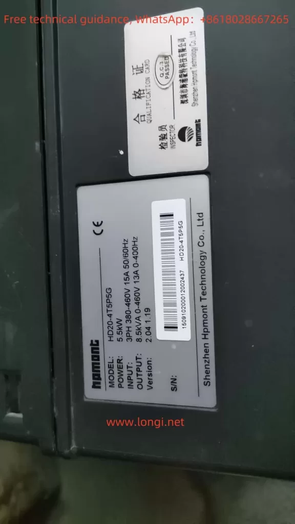
The operation panel of the HPMONT Inverter HD20 series serves as a crucial interface for user interaction with the inverter, providing a plethora of functions and convenient operation methods. The operation panel primarily comprises a display screen, various function buttons, and status indicators.
1. Parameter Copying
How to Copy Parameters:
- Uploading Parameters from Control Board to Operation Panel: Set F01.03 to 1 or 2 to copy the current function code settings to the storage parameters 1 or 2 on the operation panel.
- Downloading Parameters from Operation Panel to Control Board: Set F01.02 to 2, 3, 5, or 6 to copy the stored parameters from the operation panel to the current function code settings on the control board.
2. Setting and Removing Passwords

How to Set a Password:
- Set F01.00 to a non-zero value to enable the password protection function. The password can be any number between 00000 and 65535.
How to Remove a Password:
- Follow the password unlocking procedure (refer to the manual for details) and set F01.00 back to 00000 to clear the password.
3. Parameter Initialization
How to Initialize Parameters:
- Set F01.02 to 1 to restore the parameters to their factory default settings. Note that certain parameters (e.g., F01.00, F01.02, F01.03, F08 group, etc.) will not be affected by this operation.

II. Terminal Control and External Potentiometer Speed Regulation
1. Terminal Forward/Reverse Control
Wiring Requirements:
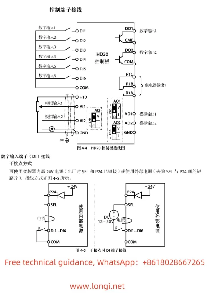
- Connect the external control signals to the appropriate terminals (e.g., DI1 for forward, DI2 for reverse).
Parameter Settings:
- Set F15.00 (DI1 terminal function) to 2 for forward and F15.01 (DI2 terminal function) to 3 for reverse.
- Ensure F00.11 (command setting channel) is set to 1 to enable terminal control.
2. External Potentiometer Speed Regulation
Wiring Requirements:
- Connect one end of the external potentiometer to AI1 (or AI2) and the other end to GND.
Parameter Settings:
- Set F00.07 (upper limit frequency setting channel) to 1 to enable analog input setting.
- Set F16.01 (AI1 terminal function) to 2 to use AI1 for frequency setting.
- Adjust the potentiometer to change the input voltage to AI1, thereby regulating the output frequency of the inverter.

III. Fault Codes and Handling
The HPMONT Inverter HD20 series provides comprehensive fault protection and diagnostic functions. The following are some common fault codes, their meanings, and handling suggestions:
- E0001: Overcurrent during acceleration. Handling: Check motor and inverter wiring, set appropriate motor parameters, and adjust acceleration time.
- E0002: Overcurrent during deceleration. Handling: Similar to E0001.
- E0003: Overcurrent during constant speed operation. Handling: Similar to E0001.
- E0015: Input phase loss. Handling: Check the three-phase input power supply.
- E0016: Output phase loss. Handling: Check the inverter output wiring and load balance.
- E0024: External device fault. Handling: Check the external device connected to the fault input terminal.
- E0025: PID setpoint loss. Handling: Check the PID setpoint signal connection.
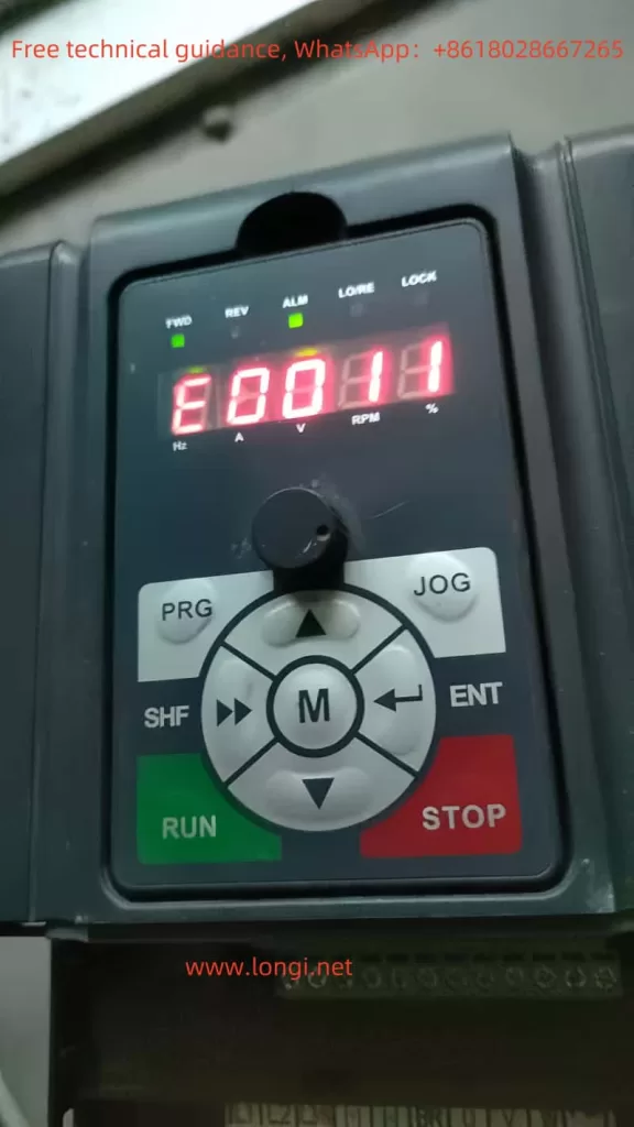
- E011: CPU fault. Handling: Try a complete power cycle; if the problem persists, contact technical support.
When a fault occurs, the inverter will display the corresponding fault code on the operation panel. Users should refer to the manual to understand the meaning of the fault code and take appropriate measures to resolve the issue. In some cases, the inverter may automatically attempt to reset the fault after a specified interval (set by F20.19). If the fault persists, manual intervention may be required.
