I. Introduction to Operation Panel Functions and Parameter Settings
1.1 Introduction to Operation Panel Functions
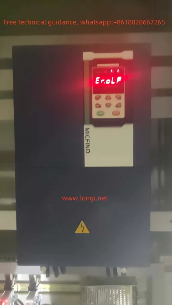
The MICFIND Frequency Inverter MT500 Series is equipped with a powerful operation panel that allows users to conveniently set parameters, monitor the inverter’s status, and troubleshoot through the keypad and display. The main function keys on the operation panel include:
- ESC: Returns to the previous menu.
- ENTER: Confirms selections, enters the next menu level, or applies parameter changes.
- UP/DOWN: Moves the cursor up or down to select function codes or change parameter values.
- M.K: Multifunction key, defaulted to “Jog Forward” function, customizable.
- SHIFT: Moves the cursor to the right, switches monitored values.
- RUN: Starts the inverter.
- STOP: Stops the inverter or resets it in case of a fault.

1.2 Setting and Removing Passwords
To prevent unauthorized personnel from changing inverter parameters, the MT500 Series supports user password settings. The specific operations are as follows:
- Setting a Password: In the stopped state, enter the same non-zero value twice to set the user password.
- Unlocking and Changing the Password: After entering the password, press ENTER twice to unlock. Enter the new password twice to change it.
- Removing the Password: After unlocking, enter “0” twice to clear the password.
1.3 Parameter Locking and Initialization
- Parameter Locking: After setting a user password, the parameters are automatically locked. Only partial parameters are accessible without unlocking. Users need to enter the password to unlock and access all parameters.
- Parameter Initialization: In the stopped state, set parameter P00.03 to “11” to restore factory settings (excluding motor parameters), “12” to restore all factory settings (including all non-factory parameters), or “13” to clear fault records. After setting the parameter, re-power the inverter.
II. Terminal Control and External Speed Regulation
2.1 Terminal Forward/Reverse Control
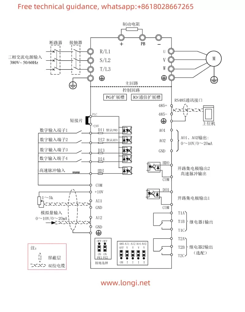
To achieve forward/reverse control through terminals, external control signals need to be connected to the inverter’s DI terminals. The specific wiring and parameter settings are as follows:
- Wiring: Connect the forward control signal to the DI1 terminal and the reverse control signal to the DI2 terminal.
- Parameter Settings: Set P06.01 (DI1 Function Selection) to “2” (Reverse Run/Forward-Reverse Switch) and P06.02 (DI2 Function Selection) to “1” (Forward Run).
2.2 External Potentiometer Speed Regulation
External potentiometer speed regulation is achieved through analog input. The specific wiring and parameter settings are as follows:
- Wiring: Connect the output end of the external potentiometer to the AI1 terminal and the other end to the AI1 COM terminal.
- Parameter Settings: Set P01.00 (Main Frequency Source Selection) to “1” (AI1). Ensure that parameters such as P04.01 (HDI Maximum Input Frequency) and P04.02 (HDI Minimum Frequency Corresponding Conversion Value) are set according to actual needs.

III. Fault Codes and Troubleshooting
The MT500 Series inverter has comprehensive protection functions. When a fault occurs, a corresponding fault code is displayed. Below are some common fault codes, their meanings, and troubleshooting methods:
- Er.GF: Ground short circuit. Possible causes include poor motor insulation or damaged cables. Troubleshooting methods include checking motor insulation resistance and cable connections.
- Er.tCK: Module temperature detection abnormality. Possible causes include low ambient temperature or hardware faults. Troubleshooting methods include increasing the ambient temperature or seeking technical support.
- Er.Cur: Current detection fault. Possible causes include abnormal current detection components or drive boards. Technical support is required.
- Er.PGL: Encoder disconnection. Possible causes include motor stall or incorrect encoder line number settings. Troubleshooting methods include checking the motor and mechanical conditions and correctly setting encoder parameters.
- Er.oS: Motor overspeed fault. Possible causes include incorrect encoder parameter settings or lack of parameter identification. Encoder parameters need to be correctly set, and motor parameter identification needs to be performed.
IV. Conclusion
The MICFIND Frequency Inverter MT500 Series User Manual provides a detailed operation guide, including introductions to operation panel functions, parameter settings, terminal control, external speed regulation, and fault troubleshooting. Through this guide, users can quickly master the basic operation methods and fault troubleshooting methods of the inverter, ensuring its normal operation and efficient use. In practical applications, users should set parameters reasonably according to specific needs and regularly maintain the inverter to extend its service life and improve operational efficiency.
