I. Introduction to the Functions of the Inverter Operation Panel
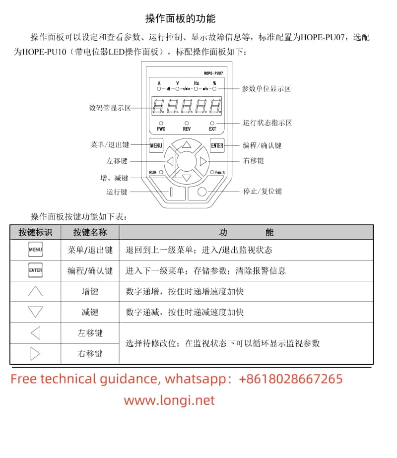
The operation panel of the Senlan Inverter HOPE130 series offers a wide range of functions and an intuitive operating interface, making it convenient for users to set parameters, control operations, and monitor faults. Below are the primary functions of the operation panel:

1.1 Functions of the Operation Panel
- Digital Display Area: Displays operational parameters such as frequency, current, and voltage.
- Parameter Unit Display Area: Indicates the unit of the currently displayed parameter, such as Hz, A, V, etc.
- Operational Status Indicator Area: Includes indicators like RUN (running) and FAULT (fault), used to show the current status of the inverter.
- Keypad Area: Includes keys such as Menu/Exit, Program/Confirm, Increase, Decrease, Left Shift, Right Shift, Run, and Stop/Reset, used for parameter setting and operational control.
1.2 Restoring Factory Settings
To restore the factory settings of the inverter, follow these steps:
- Enter the parameter editing mode and press the Menu/Exit key to access the parameter group selection interface.
- Use the Increase or Decrease keys to select the F0 parameter group.
- Press the Program/Confirm key to enter the F0 parameter group editing interface.
- Use the Increase or Decrease keys to select the F0-11 parameter and set it to 11.
- Press the Program/Confirm key to save the setting, and the inverter will automatically restore to factory settings.
1.3 Setting and Removing Passwords
To set a password, follow these steps:
- Enter the parameter editing mode and select the F0 parameter group.
- Set the F0-13 parameter to the desired password value (0000~9999).
- Press the Program/Confirm key to save the setting.
To remove the password, simply reset the F0-13 parameter to 0000.
1.4 Parameter Locking
To prevent parameters from being accidentally modified, they can be locked. Follow these steps:
- Enter the parameter editing mode and select the F0 parameter group.
- Set the F0-12 parameter to 2 to enable full protection, locking all parameters.

II. Terminal Forward/Reverse Control and External Potentiometer Speed Regulation
2.1 Terminal Forward/Reverse Control
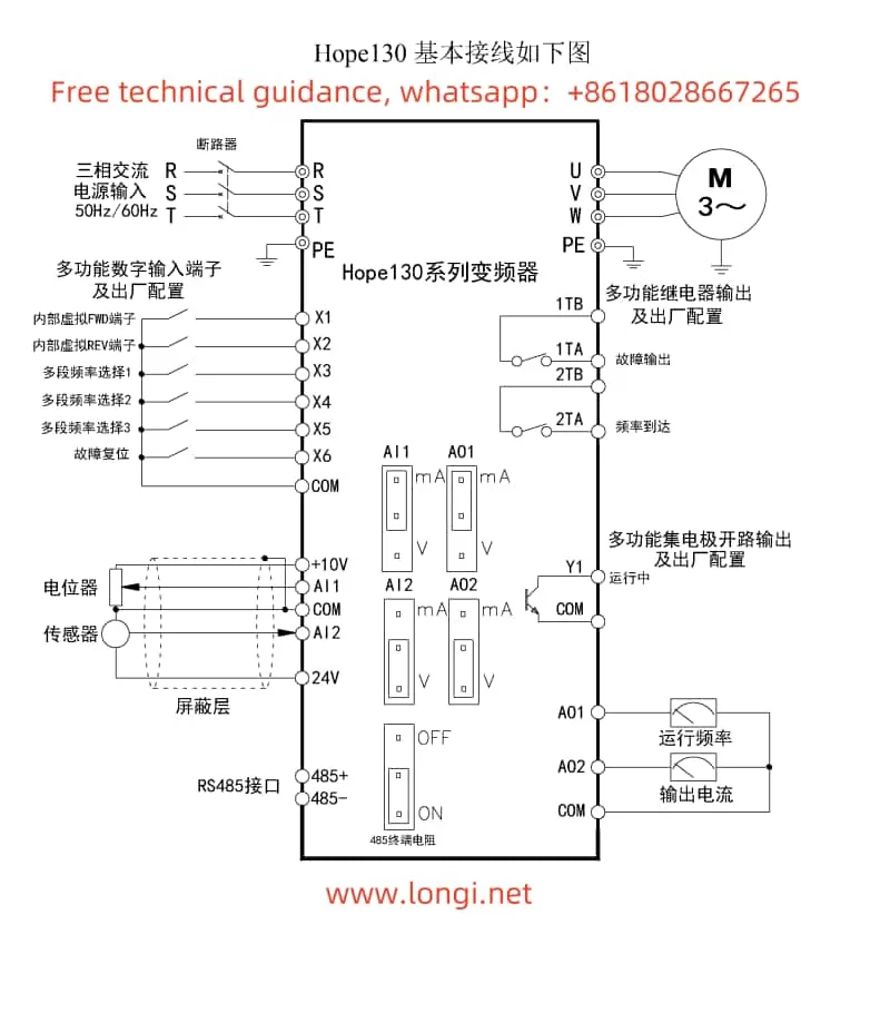
To achieve terminal forward/reverse control, the following parameters need to be set, and corresponding terminals need to be wired:
- Parameter Settings:
- F0-02: Operation Command Channel Selection, set to 2 (terminal control).
- F4-06: FWD/REV Operation Mode, select the appropriate mode (e.g., Two-Wire Mode 1).
- Wiring Terminals:
- Connect the forward control signal to the X1 terminal and the reverse control signal to the X2 terminal.
- Ensure the COM terminal is properly grounded.
2.2 External Potentiometer Speed Regulation
To achieve external potentiometer speed regulation, the following parameters need to be set, and corresponding terminals need to be wired:
- Parameter Settings:
- F0-01: Main Given Channel for Ordinary Operation, set to 4 (panel potentiometer).
- If terminal control is desired, set to 5 (AI2) and connect the AI2 terminal to an external potentiometer.
- Wiring Terminals:
- If using the panel potentiometer, no additional wiring is required.
- If using an external potentiometer, connect the two ends of the potentiometer to the AI2 and COM terminals.
III. Fault Code Analysis and Troubleshooting
The Senlan Inverter HOPE130 series provides a range of fault codes to help users quickly locate and resolve issues. Below are some common fault codes, their meanings, and solutions:
3.1 Er.ocb (Instantaneous Overcurrent at Startup)
- Meaning: Inter-phase or ground short circuit within the motor or wiring, or damaged inverter module.
- Solution: Check the motor and wiring, and seek professional service.
3.2 Er.ocA (Overcurrent During Acceleration)
- Meaning: Too short acceleration time, inappropriate V/F curve, or restarting a rotating motor.
- Solution: Extend the acceleration time, adjust the V/F curve, or set to speed tracking startup.
3.3 Er.ouA (Overvoltage During Acceleration)
- Meaning: Abnormal input voltage or restarting a rotating motor.
- Solution: Check the input power supply and set to speed tracking startup.
3.4 Er.dcL (Undervoltage During Operation)
- Meaning: Abnormal input voltage or power loss during operation, heavy load impact, or damaged charging contactor.
- Solution: Check the input power supply and wiring, inspect the load, and replace the charging contactor.
3.5 Er.oLL (Motor Overload)
- Meaning: Inappropriate V/F curve, low input voltage, long-term low-speed heavy-load operation of a standard motor, or improper motor rating or overload protection settings.
- Solution: Properly set the V/F curve and torque boost, check the input voltage, add an independent cooling fan or select an inverter-duty motor, and correctly set the motor parameters.
IV. Conclusion
The Senlan Inverter HOPE130 series user manual provides a detailed operation guide, covering the functions of the operation panel, restoring factory settings, setting and removing passwords, parameter locking, terminal forward/reverse control, external potentiometer speed regulation, and more. Additionally, the manual lists common fault codes, their meanings, and solutions to help users quickly locate and resolve issues. By carefully studying and mastering this operation guide, users can better utilize and maintain the Senlan Inverter HOPE130 series equipment.
